Selecon PLPROFILE4 MKII User manual
For PLPF4MKII-03 &
PLPF4MKII-01

The material in this manual is for information purposes only and is subject to change without notice.
Selecon assumes no responsibility for any errors or omissions which may appear in this manual. For comments and
suggestions regarding corrections and/or updates to this manual, please visit the Selecon web site at
www.seleconlight.com or contact your nearest Selecon office.
El contenido de este manual es solamente para información y está sujeto a cambios sin previo aviso.
Selecon no asume responsabilidad por errores o omisiones que puedan aparecer. Cualquier comentario, sugerencia
o corrección con respecto a este manual, favor de dirijirlo a la oficina de Selecon más cercana.
Der Inhalt dieses Handbuches ist nur für Informationszwecke gedacht, Aenderungen sind vorbehalten.Selecon
uebernimmt keine Verantwortung für Fehler oder Irrtuemer, die in diesem Handbuch auftreten. Für
Bemerkungen und Verbesserungsvorschlaege oder Vorschlaege in Bezug auf Korrekturen und/oder
Aktualisierungen in diesem Handbuch, moechten wir Sie bitten, Kontakt mit der naechsten Selecon-
Niederlassung aufzunehmen.
Le matériel décrit dans ce manuel est pour information seulement et est sujet à changements sans préavis. La
compagnie Selecon n'assume aucune responsibilité sur toute erreur ou ommission inscrite dans ce manuel.Pour
tous commentaires ou suggestions concernant des corrections et/ou les mises à jour de ce manuel, veuillez s'ilvous
plait contacter le bureau de Selecon le plus proche.
Note: Information contained in this document may not be duplicated in full or in part by any person without prior written
approval of Selecon. Its sole purpose is to provide the user with conceptual information on the equipment mentioned. The use of
this document for all other purposes is specifically prohibited.
Document Number: 02.9694.4202 A
Version as of: 25 February 2016
PLPROFILE4 MKII LED Luminaire QuickStart Guide
©2016 Philips Group. All rights reserved.
Website:
www.vari-lite.com

1
PLPROFILE4 MKII LED Luminaires QuickStart Guide
TABLE OF CONTENTS
6elecon Offices....................................................................................................... Inside Front Cover
TABLE OF CONTENTS
IMPORTANT INFORMATION
Warnings and Notices ..................................................................................................................................... 2
Additional Resources for DMX512 ................................................................................................................ 2
Selecon Limited Three-Year Warranty............................................................................................... 2
PREFACE
About this Guide..................................................................................................................................................... 3
Product Descriptions .............................................................................................................................................. 3
Included Items ........................................................................................................................................................ 3
INSTALLATION AND SET UP
Top Box Connections ............................................................................................................................................. 4
Power Requirements............................................................................................................................................... 4
Connecting Power .................................................................................................................................................. 5
Connecting to the DMX512 Network .................................................................................................................... 5
Mounting ................................................................................................................................................................ 6
Using Supplied C-Clamp ................................................................................................................................ 6
Pan and Tilt Adjustments ....................................................................................................................................... 7
Pan Adjustment ............................................................................................................................................... 7
Tilt Adjustment ............................................................................................................................................... 7
FOCUS AND BEAM ADJUSTMENTS
Lens Tube Removal and Installation ...................................................................................................................... 8
Zoom and Focus Adjustments (Zoomspot Models) ............................................................................................... 9
Beam Shutter Operation ....................................................................................................................................... 10
Gobo/Iris Access Panel......................................................................................................................................... 10
OPERATION AND PROGRAMMING
LCD Menu Operation........................................................................................................................................... 12
LCD Menu System ............................................................................................................................................... 13
Security................................................................................................................................................................. 13
Locking Fixture ............................................................................................................................................. 14
Presets................................................................................................................................................................... 14
Editing Preset Names .................................................................................................................................... 14
Settings ................................................................................................................................................................. 14
TROUBLESHOOTING
Troubleshooting Guide ......................................................................................................................................... 16
CLEANING AND CARE
Special Cleaning and Care Instructions................................................................................................................ 17
Service and Maintenance...................................................................................................................................... 17

QuickStart Guide PLPROFILE4 MKII LED Luminaires
2IMPORTANT INFORMATION
IMPORTANT INFORMATION
Warnings and Notices
Additional Resources for DMX512
For more information on installing DMX512 control systems, the following publication is available for purchase
from the United States Institute for Theatre Technology (USITT), "Recommended Practice for DMX512: A Guide
for Users and Installers, 2nd edition" (ISBN: 9780955703522). USITT Contact Information:
USITT
315 South Crouse Avenue, Suite 200
Syracuse, NY 13210-1844
Phone: 1.800.938.7488 or 1.315.463.6463
www.usitt.org
Selecon Limited Three-Year Warranty
Selecon offers a three-year limited warranty of its luminaires against defects in materials or workmanshipfrom
the date of delivery. A copy of Selecon three-year limited warranty containing specific terms andconditions
can be obtained from the Selecon web site at www.seleconlight.com or by contacting your localSelecon office.
When using electrical equipment, basic safety precautions should always be followed including the following:
a. READ AND FOLLOW ALL SAFETY INSTRUCTIONS.
b. Do not use outdoors.
c. Do not mount near gas or electric heaters.
d. Equipment should be mounted in locations and at heights where it will not readily be subjected to
tampering by unauthorized personnel.
e. The use of accessory equipment not recommended by the manufacturer may cause an unsafe
condition.
f. Do not use this equipment for other than intended use.
g. Refer service to qualified personnel.
h. Luminaire exterior surface temperatures:
• After 5 minutes of operation: 45oC
• When steady state is achieved: 50o C
SAVE THESE INSTRUCTIONS.
WARNING: You must have access to a main circuit breaker or other power disconnect device
before installing any wiring. Be sure that power is disconnected by removing fuses or turning the
main circuit breaker off before installation. Installing the device with power on may expose you to
dangerous voltages and damage the device. A qualified electrician must perform this installation.
WARNING: Basic insulation has been maintained between low-voltage supply and control
conductors.
WARNING: Refer to National Electrical Code® and local codes for cable specifications. Failure to
use proper cable can result in damage to equipment or danger to personnel.
WARNING: This equipment is intended for installation in accordance with the National Electric
Code® and local regulations. It is also intended for installation in indoor applications only. Before
any electrical work is performed, disconnect power at the circuit breaker or remove the fuse to avoid
shock or damage to the control. It is recommended that a qualified electrician perform this
installation.
About this Guide 3
PLPROFILE4 MKII LED Luminaires QuickStart Guide
PREFACE
1. About this Guide
This Quickstart Guide is intended for a knowledgeable user to unpack, install, and use the PLPROFILE4 MKII LED
Luminaire in a short time period. For the complete manual in PDF format, please visit our web site at:
www.seleconlight.com and click the user manual download link on the product page. The complete manual provides
you all information related to accessories, menu structures, DMX channel mapping/modes, and care for your new
luminaire.
Please read all instructions before installing or using this product. Retain this guide for future reference. Additional
product information and descriptions may be downloaded at www.seleconlight.com.
2. Product Descriptions
The document provides installation and operation instructions for the following products:
• PLPROFILE4 MKII LED Luminaire, Black Body (PLPF4MKII-03).
• PLPROFILE4 MKII LED Luminaire, White Body (PLPF4MKII-01).
Note: All PLPROFILE4 MKII LED Luminaires are universal voltage (100VAC to 240VAC, Auto-ranging).
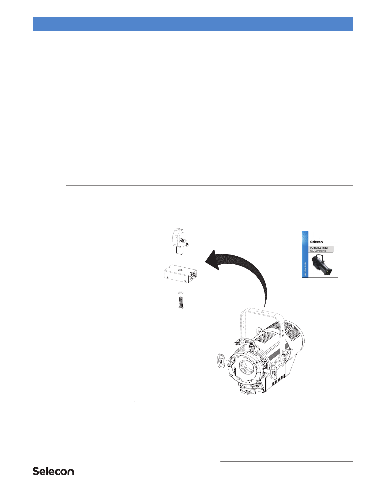
3. Included Items
The following items are supplied with the luminaire.
Figure 1: Included Items
Note: For all accessories and options for this luminaire, please refer to the product specification sheet - available
for download from the Selecon or Strand Lighting web sites in PDF format.
C-Clamp
Top Box
Belleville Washer
C-Clamp Bolt
Luminaire Body
QuickStart Guide
(this document)
Not Shown:
• Depending on order configuration, a lens tube may be
provided. Luminaire body available without lens tube.
• Safety Cable (provided with unit)
• Unit provided with a PowerCON to bare end AC input
cable. Others available. Specify at time of ordering.
QuickStart Guide PLPROFILE4 MKII LED Luminaires
4INSTALLATION AND SET UP
INSTALLATION AND SET UP
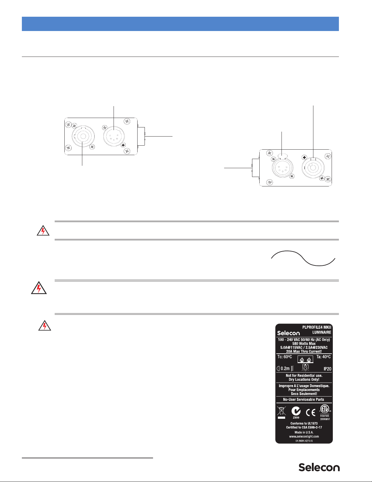
1. Top Box Connections
All PLPROFILE4 MKII LED Luminaires are supplied with a "Top Box" for AC Input/Output and DMX512 Input/
Output Connections. Figure 2 shows the AC and DMX512 Input and Output (Thru) Connections.
Figure 2: PLPROFILE4 MKII LED Luminaire Top Box Connections
2. Power Requirements
WARNING! The PLPROFILE4 MKII LED Luminaire should be connected to a constant circuit or a relay device. It
should never be connected to a dimmer or circuit controlled by a dimmer.
The PLPROFILE4 MKII LED Luminaire operates on 100 to 240 volts AC (+/- 10%,
auto-ranging). The luminaire contains an auto-ranging power supply. Depending on
supply voltage, each luminaire can draw up to 580 Watts. The maximum through
current should not exceed 20 Amps*.
WARNING! *Maximum Allowable Input Current of 20 Amps (maximum power supply limit of 580 Watts). Do not
overload circuits! Must be supplied by a branch circuit protected by a maximum 20 Amp circuit protector. Doit
être alimenté par un circuit de dérivation protégé par un maximum de 20 ampères circuit protecteur. Do not
overload circuits!
IMPORTANT AC POWER CONNECTION NOTES:
a. Must be supplied by a branch circuit protected by a maximum 20 Amp
circuit protector. Doit être alimenté par un circuit de dérivation protégé
par un maximum de 20 ampères circuit protecteur.
b. When using the daisy-chain connection method, ONLY connect
PLPROFILE4 MKII LED Luminaires to AC Output Connection of
PLPROFILE4 MKII LED Luminaires. DO NOT CONNECT OTHER
TYPES OF LUMINAIRES OR DEVICES!
c. Use only approved cable types.
d. Do not overload circuits!
e. Do not connect PLPROFILE4 MKII LED Luminaires to dimmed circuits.
f. The MAXIMUM allowable number of PLPROFILE4 MKII LED
Luminaires which can be 'daisy-chained' on one power feed should not
exceed ratings. DO NOT EXCEED!
DMX512 Output/Thru
DMX512 Input AC (Power) Output
AC (Power) Input
Multi-Conductor Top Box
to Luminaire Connection
Multi-Conductor Top Box
to Luminaire Connection
Side View 1
Side View 2
AC Input Only!

Connecting Power 5
PLPROFILE4 MKII LED Luminaires QuickStart Guide
3. Connecting Power
Note: Refer to Figure 2 on page 4 for AC Input and Output connections.
If the unit is supplied with an AC input cable, Table 1 describes how to connect power to your PLPROFILE4 MKII
LED Luminaire. Field wiring of the PLPROFILE4 MKII LED Luminaire is straight forward. A total of 3 wires/
conductors need to be brought to the unit. The following wiring scheme is required:
Table 1: PLPROFILE4 MKII LED Luminaire AC Input
Connections
4. Connecting to the DMX512 Network
Note: Refer to Figure 2 on page 4 for DMX512 Input and Output/Thru connections.
Basic DMX512 installation consists of connecting multiple PLPROFILE4 MKII LED Luminaires together (up to 30
luminaires) in "daisy-chain" fashion. A cable runs from the control console (or DMX512 control source) to the DMX
connector on the first PLPROFILE4 MKII LED Luminaire. Another cable runs from the other DMX connector on the
first unit to a DMX connector on the next PLPROFILE4 MKII LED Luminaire (or DMX512 device to be controlled)
Note: For more information on DMX512 networking and systems, refer to "Additional Resources for DMX512" on
page 2. For PLPROFILE4 MKII LED Luminaire DMX Mapping, refer to the product user’s manual.
Figure 3: Connecting DMX512
Wire Color Purpose
Brown Main / Line (100 to 240VAC)
Blue Neutral
Green/Yellow Ground
Neutral Main /
Ground / Earth
Line
AC Input Connector
(on top box)
DMX512
DMX512 (out from first
to second luminaire)
DMX512 (out to the next luminaire or
DMX512 controlled device)
(from console or
control device)
DMX512 Connections
Data Thru
Cable Pinout
Male Conn
Pin 1
Common
(Drain)
Pin 2
Data (-)
Pin 3
Data (+)
Pin 4
Not Used
Pin 5
Not Used
Data In
Cable Pinout
Female Conn
1
2
3
4
5
1
2
3
4
5
PLPROFILE1 MKII LED Luminaires

QuickStart Guide PLPROFILE4 MKII LED Luminaires
6INSTALLATION AND SET UP
5. Mounting
WARNING! Before attempting any installation or service, disconnect all power at power source. Dimming the
luminaire does not disconnect power. Installation and service should only be performed by a trained and qualified
professional.
Using Supplied C-Clamp
As illustrated in Figure 4 on page 6, at yoke assembly, thread clamp mounting bolt (with washer installed) through
center clamp mounting hole at top of yoke, through Top Box Assembly, and thread bolt into C-Clamp. Securely
tighten bolt (by hand) into clamp (but do not over-tighten).
Note: Top box will be able to swivel once bolt is tightened by design. DO NOT OVER-TIGHTEN!
Figure 4: Luminaire Mounting
To mount on a telescopic stand, reverse the yoke under the luminaire and bolt to stand. Please note luminaire
orientation (see note in Figure 4) for proper cooling.
Yoke Assembly
Center Clamp Mounting Hole
Luminaire Cooling Vents**
NOTES:
• * Only use supplied bolt when mounting top box
as shown. Using another bolt may damage top
box when tightening.
• **To allow for proper cooling, make sure lumi-
naire head is orientated as shown (with cooling
vents pointed upwards).
Top Box Assembly
C-Clamp
Flat Washer
C-Clamp Bolt*
Top Box Assembly
Luminaire Cable
Assembly
Pan and Tilt Adjustments 7
PLPROFILE4 MKII LED Luminaires QuickStart Guide
Note: After installing Clamp and Top Box assembly, connect luminaire cable assembly to Top Box Assembly before
mounting luminaire. Please note that the cable connector is keyed.
The supplied safety cable MUST always be used when rigging luminaires on bars, truss, etc. (as shown in Figure 5).
The supplied safety cable is recommended for all hanging installation and may be required by national and local
codes. Loop or attach safety cable to luminaire safety cable anchor point as shown and attach to structure. You should
always consult and follow all local and national codes and regulations for mounting and installation of luminaire.
6. Pan and Tilt Adjustments
Pan Adjustment
The pan adjustment of a PLPROFILE4 MKII LED Luminaire is achieved by loosening the yoke bolt of the securing
clamp attached to the luminaire's yoke assembly. Loosen the bolt, set the luminaire to the desired position and re-
tighten.
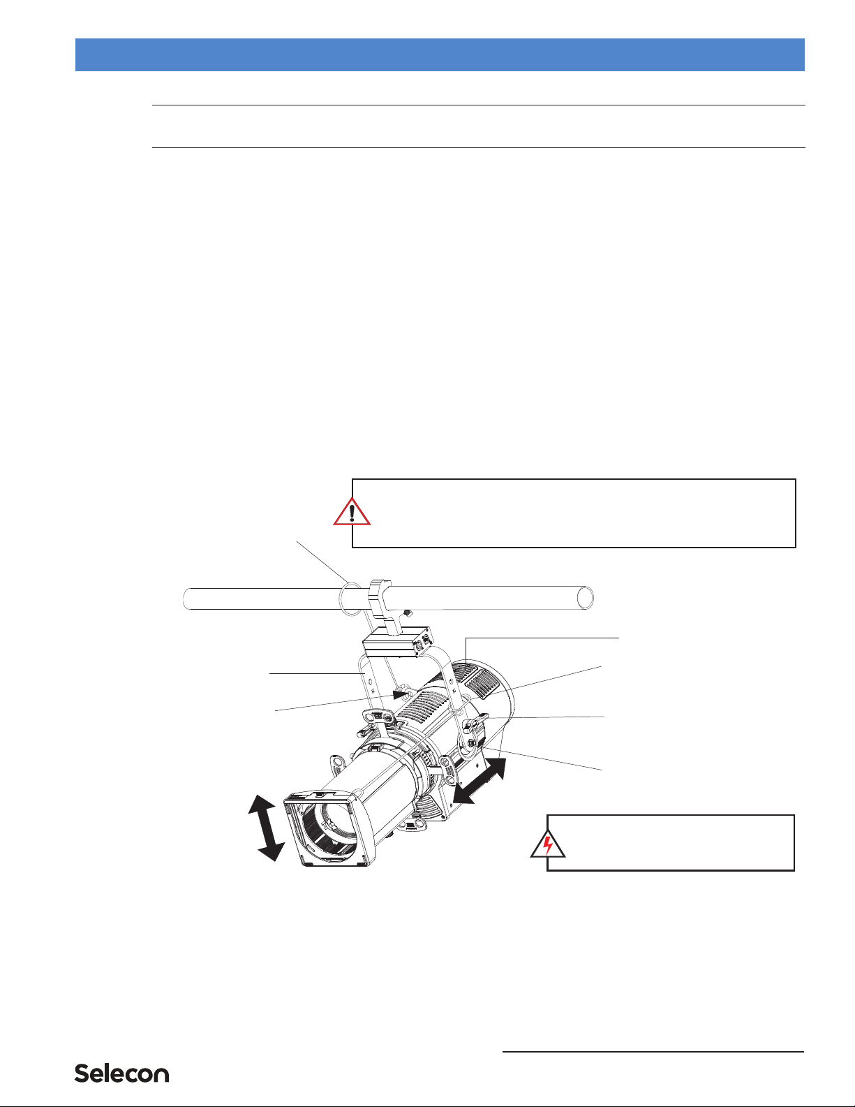
Tilt Adjustment
PLPROFILE4 MKII LED Luminaires offer variable tilt settings. The unit can be set at a specific angle (in relation to
its mounting position) or at an angle between 0 to 90 degrees. When the yoke is in the position shown in Figure 5,
you have full range access to shutters the gate etc. If you flip the yoke over some access is reduced but the over all
volume the luminaire takes up is reduced. This is particularly useful in tightly hung lighting positions or in theatres
with low grids.
Figure 5: Luminaire Tilt Adjustment
To adjust and set tilt angle of the luminaire:
Step 1. Mount luminaire in desired location (see "Mounting" on page 6 for more information).
Step 2. Loosen, but do not remove, T-Handle Tilt Lock at base of yoke assembly as shown in Figure 5.
Step 3. Position luminaire to desired tilt position.
Step 4. Re-tighten T-Handle Tilt Lock to set position.
SAFETY CABLE: FOR LUMINAIRE, the supplied safety cable is recommended for
all hanging installation and may be required by national and local codes. Loop
safety cable through luminaire safety cable anchor point. FOR LENS TUBE, attach
a safety cable (sold separately) to lens tube anchor point and to yoke assembly.
Yoke Assembly
Cooling Vents (see note below)
T-Handle Tilt Lock
NOTE: To allow for proper cooling, make
sure luminaire head is orientated as shown
(with cooling vents pointed upwards).
(one on each side)
Safety Cable
Sliding Yoke Assembly
(supplied with
luminaire)
Safety Cable
(sold separately)
Safety Cable
Anchor Point
QuickStart Guide PLPROFILE4 MKII LED Luminaires
8FOCUS AND BEAM ADJUSTMENTS
FOCUS AND BEAM ADJUSTMENTS
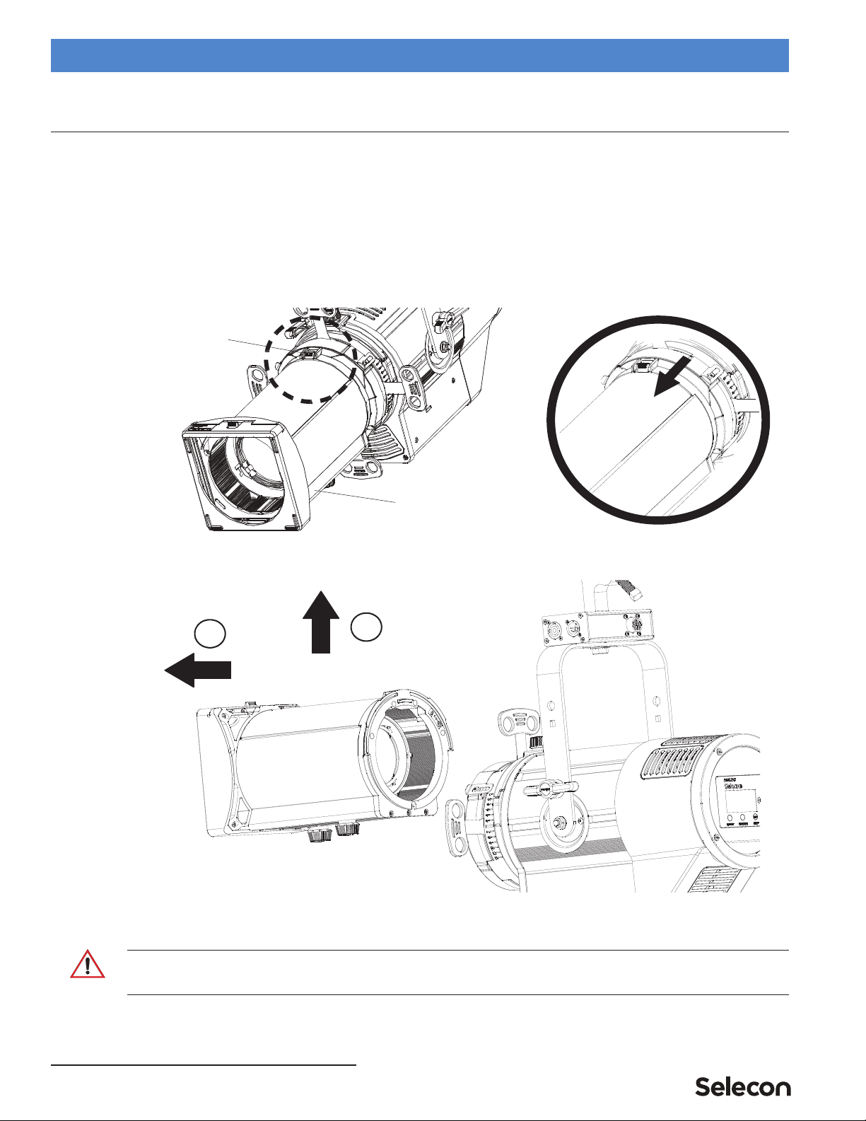
1. Lens Tube Removal and Installation
It is easy and quick to change to the lens tubes on a PLPROFILE4 MKII LED Luminaire. Fixed beam and zoom lens
tubes are interchangeable.
To remove and install lens tubes:
Step 1. Loosen (but do not remove) move lens knob(s) towards front of lens tube assembly. See "Zoom and Focus
Adjustments (Zoomspot Models)" on page 9 for more information.
Step 2. As illustrated Figure 6, side lens tube locking catch forward.
Figure 6: Lens Tube Assembly Removal - Lens Locking Catch
Step 3. Lift lens tube assembly up and away from light engine assembly.
Figure 7: Lens Tube Assembly Removal
Step 4. To install perform process in reverse.
CAUTION: Ensure the lens tube locking catch is fully engaged and safety cable is attached before putting fixture
into use. For safety cable attachment, refer to Figure 5 on page 7 for more information.
Lens Tube Assembly
Lens Tube Lock
1
2

Zoom and Focus Adjustments (Zoomspot Models) 9
PLPROFILE4 MKII LED Luminaires QuickStart Guide
2. Zoom and Focus Adjustments (Zoomspot Models)
Note: Fixed Beam Angle models have hard/soft focus adjustment only.
To adjust zoom/beam angle and focus:
Step 1. Make sure all frame shutters are open (out of beam path). See "FOCUS AND BEAM ADJUSTMENTS" on
page 8 for more information.
Step 2. As shown in Figure 8, loosen Zoom Adjustment Knob and set beam angle as desired.
Step 3. Hand-tighten Zoom Adjustment Knob to lock position.
Step 4. Loosen Focus Adjustment Knob.
Step 5. Move Focus Adjustment Knob along forward (or back) until beam focus is set as desired.
Step 6. Hand-tighten Focus Adjustment Knob to lock position.
Figure 8: Zoom and Focus Adjustment Knobs
Lens Tube Assembly
Zoom Adjustment Knob
Shutter (4 ea.)
Focus Adjustment Knob

QuickStart Guide PLPROFILE4 MKII LED Luminaires
10 FOCUS AND BEAM ADJUSTMENTS
3. Beam Shutter Operation
Each PLPROFILE4 MKII LED Luminaire is equipped with four independent shutters (as shown in Figure 9) to
block or shape light as desired. After the luminaire is installed and positioned, move the shutters in or out as required.
Use the shutter lock to lock-in the shutter settings.
Figure 9: PLPROFILE4 MKII LED Luminaire Beam Shutters
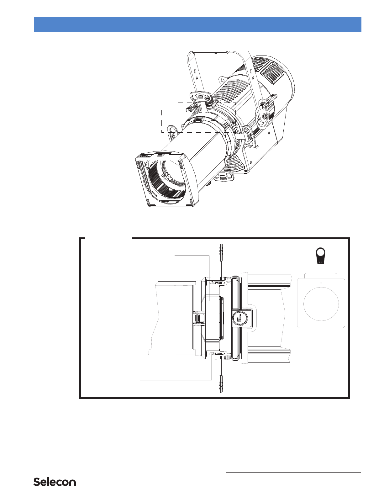
4. Gobo/Iris Access Panel
Each PLPROFILE4 MKII LED Luminaire is capable of holding two gobo holders, each containing one "B" sized
glass or steel gobo. PLPROFILE4 MKII LED Luminaire are not supplied gobo holders or an iris. These items can be
purchased from your local Authorized Dealer.
To install or change a gobo:
Step 1. As shown in Figure 10 on page 11, loosen, but do not remove, two retaining screws that secure gobo/iris
access panel. Slide open gobo/iris access panel.
Step 2. Install gobo into gobo holder in desired orientation.
Step 3. Slide gobo holder into luminaire gobo slot.
Step 4. Close gobo access door. Make sure gobo holder handle fits inside one of two slots in gobo access panel.
Beam Shutters
(4 Each)
Front View
Move beam shutters
in and out as desired.
Shutter Lock
See Detail
Shutter Lock Detail
Shutter Lock
Gobo/Iris Access Panel 11
PLPROFILE4 MKII LED Luminaires QuickStart Guide
Step 5. Hand tighten gobo access panel retaining screws.
Figure 10: PLPROFILE4 MKII LED Luminaire Gobo Holder and Gobo Installation
Gobo / Iris Access Panel
Detail
Gobo
Area
Gobo Holder
Panel Retaining Screw
(2 Each)
See Detail
QuickStart Guide PLPROFILE4 MKII LED Luminaires
12 OPERATION AND PROGRAMMING
OPERATION AND PROGRAMMING
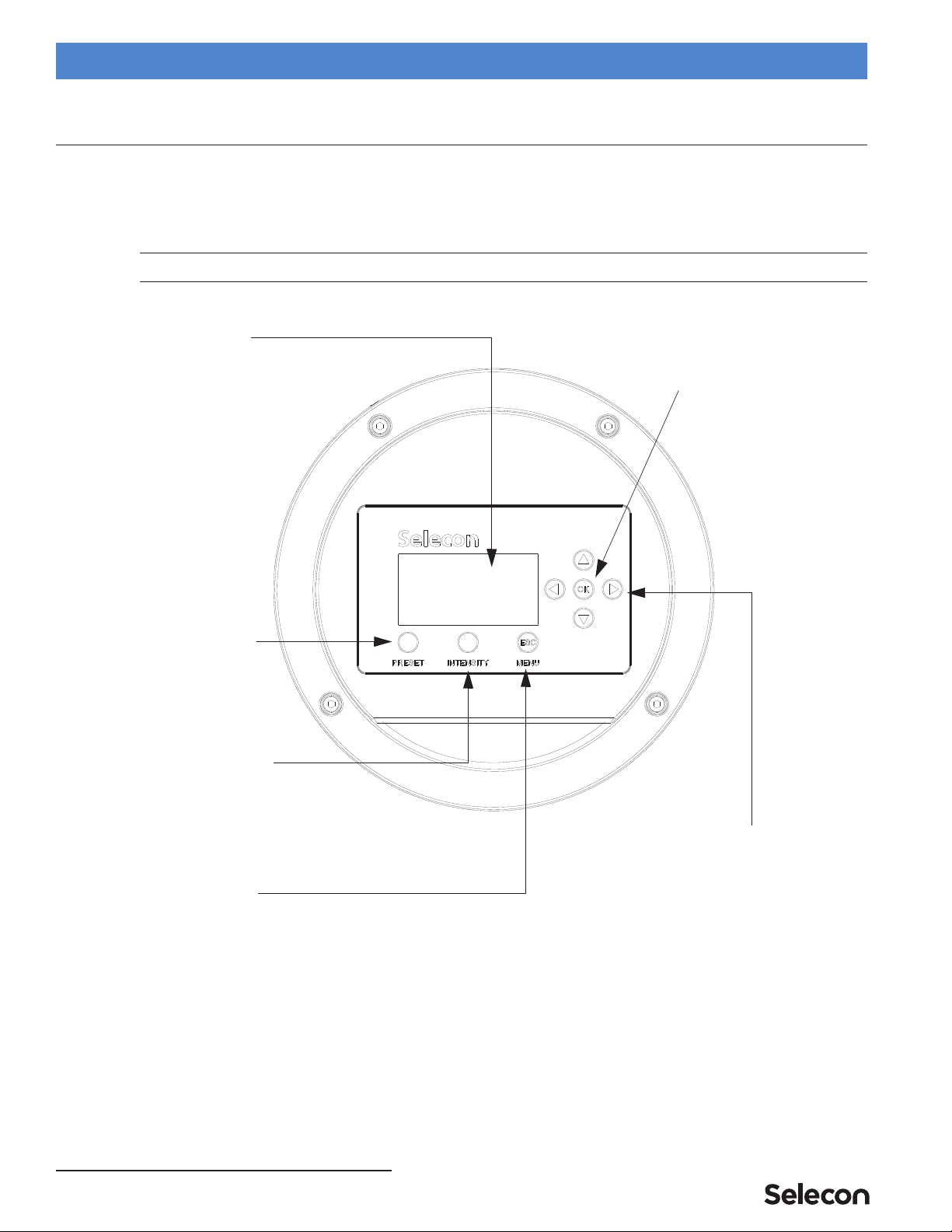
1. LCD Menu Operation
The PLPROFILE4 MKII LED Luminaire’s LCD Display and Menu System provides local control for accessing all
the fixture’s status information, menu options, and settings.
Note: If there are multiple luminaires in a system, changes would need to be made at each LCD Menu as desired.
Upon power up, the LCD will display the main screen showing the product type/name.
Figure 11: LCD Display and Menu System
2. LCD Menu System
The LCD Display Menu system consists of several categories. Use the four arrow buttons as required (refer to Figure
11 on page 12) to access and make changes to the menu items. When the desired menu item is reached, press [OK] to
display the menu options. Use navigation and [OK] buttons to view status and configure the LCD Menu as required.
To navigate and access menu settings/selections:
Step 1. At Main Menu, press [ESC] / [MENU] button once. Another window will appear with sub-menu categories:
Up/Down/Left/Right Arrow Buttons -
Navigates menu system and used for
Escape Button -
Enters menu options.
OK (Enter) Button -
Accesses details, activates
a field, or enters a setting
depending on the current menu item.
selecting and setting options.
Navigates (backs up)
PRESET Button -
Allows the recall of
LCD Display -
Displays all menu parameters and
option settings. Also displays DMX512
address (DMX models only).
stored presets.
INTENSITY Button -
Allows the customization of current
intensity (light output). Note, using
the LEFT and RIGHT arrow buttons
you can select each RGBW
channel individually and change
their intensity using the UP and
DOWN arrows.
one menu level.

Security 13
PLPROFILE4 MKII LED Luminaires QuickStart Guide
• Save as Preset
• Edit a Preset
• Color Mixer
• Settings
• Lock Fixture
• Fixture Status
• Normalize Colors
Step 2. Press [OK] at desired menu item to access and make changes.
Step 3. Make changes as desired.
Note: When DMX512 signal is present, Edit Preset and Color Mixer options will not appear in menu structure.
To navigate fixture status menus:
Step 1. At default screen, press LEFT or RIGHT arrow button once. The default menu screen will change to allow
for quick reference to the following items (note, depending on which arrow button is pressed, status screens
may appear in reverse order):
a. DMX Address (note, if fixture is UNLOCKED, hit [OK] to change DMX address).
b. Fixture Hours (displays fixture operating hours since last reset).
c. Fixture Power (displays present power consumed by fixture (in Watts).
d. Fixture Status (displays DMX or Preset selected, temperature, LED Status, fan status).
Step 2. Press LEFT or RIGHT arrow buttons to scroll through status screens.
Step 3. Press [ESC] at anytime to access Main Menu.
Note: When DMX512 signal is present, Edit Preset and Color Mix options will not appear in menu structure.
3. Security
Unwanted changes to the Fixture's Configuration or Setting can be controlled by locking the fixture’s menu.
PLPROFILE4 MKII LED Luminaires are shipped with a default numeric PIN code of "0000" (four zeros). Users may
set their own PIN code (four-digit number) via Settings > General > Set PIN. When setting a PIN code, write it
down and keep it in a secure location. Note, Selecon does not have records of PIN codes established by usersor
owners.
Note: Contact Selecon technical support if a unit is locked and the PIN code is lost for instructions on how to reset
luminaire.
Note: If the Fixture is locked when it is powered down the fixture will remain in the locked state when powered up.
Locking Fixture
To lock the fixture:
Step 1. At Main Menu, press [MENU] and scroll to Lock Fixture. Note, default PIN is "0000" (four zeros).
Step 2. Press [OK].
Step 3. Enter four-digit, user-selectable, PIN code.

QuickStart Guide PLPROFILE4 MKII LED Luminaires
14 OPERATION AND PROGRAMMING
Step 4. Use [LEFT ARROW] or [RIGHT ARROW] keys to highlight "YES", press [OK] or [ESC] twice to cancel
action.
Step 5. Fixture is now locked if locking process was not canceled as described in previous step.
Note: When the Fixture is Locked only the [ESC]/[MENU] key is functional. Pressing this key will display a request
for a password. When a valid PIN code is entered the fixture is unlocked.
4. Presets
Presets are Color Mixes that are stored in the Fixture, they can be recalled to reproduce a specific output from the
fixture. Presets are made up of a Color Mix; Red, Green, Blue, and White. They also have Intensity associated with
them.
Presets can be recalled via the User interface or by a DMX channel, when under DMX control. The Preset’s Intensity
is applied if the User Interface is used; if DMX, the DMX Intensity channel is used for Intensity.
If the fixture is locked, Presets cannot be changed at the menu.
• Locked Presets are factory Calibrated, and their Color Mix cannot be changed by the user. Their Intensity can be
changed. Three Presets (2-4), "Warm White', "Cool White", and "Day Light", are Locked.
• Preset 0, the "off" preset is also Locked to the OFF value.
•If the fixture is unlocked, User Presets can have their Color Mix and Intensity changed without restriction.
Note: If the Color Mix of a Factory Calibrated Preset is changed, by turning protection Off, an '*' is appended to the
end of the Preset's Name to indicate that the Calibrated values have been changed.
Note: DMX will take priority over any menu selected preset.
Editing Preset Names
On the Edit Preset screen, the option is available to edit the name of a preset, via Screen button. However, the names
of Presets 0, 2, 3, and 4 cannot be edited. Scratch Pad, preset 1, can be changed but retains its original functionality.
Use the [LEFT ARROW] and [RIGHT ARROW] keys to select the character to be changed and use the [UP
ARROW] and [DOWN ARROW] keys to change that character. The Character Scroll order is A-Z, space, 0-9. If you
are scrolling up the Alpha character displays as Upper Case; if you are scrolling down the Alpha character displays as
Lower Case. Stop on the character you want, ignoring case, then press the opposite [UP ARROW] or [DOWN
ARROW] key if you want to change the case. [OK] to save changes, [ESC] to cancel changes.
5. Settings
Table 2, “Settings Menu User-Settable Parameters,” on page 15 shows the user-settable parameters available in the
Settings menu section.
To edit a value on the Setting Screen, use the [UP ARROW] or [DOWN ARROW] keys to move the highlight to the
settings value you wish to change. Press [OK] to begin editing that value. Use the [UP ARROW], [DOWN
ARROW], [LEFT ARROW] or [RIGHT ARROW] keys to make changes to the value. Press [OK] when complete to
save changes, or [ESC] to cancel changes to that value.
When done making changes on the Settings Screen press [ESC] to re-boot fixture and implement changes. Fixture
will not re-boot if nothing was changed.

Settings 15
PLPROFILE4 MKII LED Luminaires QuickStart Guide
Table 2: Settings Menu User-Settable Parameters
Note: To Exit the Settings screen, use the [ESC] key. [ESC] and [OK] can be used to cancel or save changes to an
individual parameter. However, once a parameter has been accepted, by pressing [OK] that change cannot be undone/
canceled by pressing the [ESC] key.
Parameter Values Default Description
General
Fan Full, Medium, or Quiet
Mode Quiet Mode Sets the luminaire’s output mode - Full
Mode, Medium Mode, or Quiet Mode.
Power-Up All presets Warm White
Users can set what the default preset is
when the unit is powered up. Factory
default is Warm White.
Red Correct No (off) / Yes (on) No
Red Correct (Correction) is internal
processing by the fixture that
compensates for the output variations that
occur in all red LEDs due to changes in
temperature. This compensation is
important if the colors of a fixture in a hot
environment needs to appear similar to
the colors of a fixture in a cooler
environment. With red correction on, there
will be a perceptible difference in output
vs. red correction off.
Power Save Enable / Disable Enable Power Save sets fixture in a low-power
sleep mode.
Reset Hours No, Yes No Resets luminaire’s operational hours.
Set PIN #### 0 0 0 0 (four zeros) A four-digit user-settable PIN code to lock
the fixture.
Presets
Protected No, 5 - 25 5 - 25 Determines if the factory Presets' Color
Mix is protected from changes.
Load Factory No, Yes No Reload Factory Presets, Intensity changes
will also be reloaded.
DMX
Address 001 to 512 001 DMX512 address. Note, it can be set if
displayed.
Map 8-bit, 16-bit, or 5-Chan 16-bit
Defines size/precision of DMX map. Color
Mixing/Intensity in 16-bit provides higher
resolution for precision control. 5-Chan
provides minimal channel usage.
When no DMX
Off, Hold, Hold 10min,
Hold 30min, Hold 1 hr,
Hold 8hr, Power Up
Hold
If DMX is detected and then goes away,
this defines what will happen to the output.
At end of 8Hr hold Fixture goes to No
Output setting.
Display
Flip Display No, Yes No Flips (inverts) Display and Keypad Arrows.
Adj Contrast 0 - 100% 50% Use left or right arrow keys to adjust
display contrast as desired.
Fixture
Fixture ID Shows Fixture Type - PLProfile4, Profile, Cyc, or
Fresnel Shows luminaire type.
QuickStart Guide PLPROFILE4 MKII LED Luminaires
16 TROUBLESHOOTING
TROUBLESHOOTING
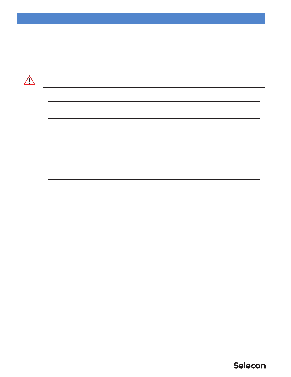
1. Troubleshooting Guide
The chart below provides possible causes and remedies for various error messages and/or symptoms.
WARNING! Any service and maintenance (including troubleshooting), other than described herein should be
performed by an Authorized Selecon Dealer or Service Center.
Description Symptom Possible Cause/Remedy
No light output. Fixture will not produce or
output light
Unit is set to Preset Off...
Make sure unit is set to proper Preset.
DMX command to 0 intensity...
Adjust intensity to higher level.
No power at luminaire. Luminaire does not power up
Circuit not energized...
verify circuit breaker is turned on.
Not plugged in...
ensure A/C cable is connected to power source.
Power cable wired incorrectly...
verify power cable and connector are wired correctly.
See "Connecting Power" on page 5 for more information.
DMX Data Control. Fixture will not respond to DMX
commands.
Not detecting DMX data...
Disconnect and reconnect DMX input cable.
Unit is not set to be controlled by DMX - check menu settings.
Check all DMX connections (at control source and luminaire).
DMX data cable not wired correctly or has a broken conductor...
check DMX data cable for proper wiring.
See "Connecting to the DMX512 Network" on page 5 for more
information.
LED (light) is getting dimmer. Fixture appears not to be
operating at full brightness.
Luminaire has detected an over temperature condition...
The luminaire will reduce power to its LEDs if it senses that the
LEDs are operating over the specified temperature. LED
temperature is read and recorded through a thermistor imbedded in
the LED chip.
Fan is not operating. Listen for fan operation or adjust settings to
increase fan speed. On luminaires with a display check system
status menu for status of fans and LED operation.
Local programming. Unit will not allow local
programming or changes.
Password protection is on (locked)...
Input proper password to allow local programming and/or
adjustments.
Unit is controlled by DMX...
Disconnect input cables to check issue.
Special Cleaning and Care Instructions 17
PLPROFILE4 MKII LED Luminaires QuickStart Guide
CLEANING AND CARE
WARNING! All cleaning should be performed with power completely removed from the luminaire. Never remove
protective covers when luminaire is powered. Wear appropriate protective eye wear and gloves when cleaning the
fixture. All service and maintenance, other than described herein, should be performed by a qualified technician or
Authorized Service Center.
1. Special Cleaning and Care Instructions
Being a solid-state fixture, and unlike most fixtures, the PLPROFILE4 MKII LED Luminaire requires very little
routine maintenance by the user. This section covers portions of the luminaire that can be removed for cleaning.
The PLPROFILE4 MKII LED Luminaire requires special care when it comes to cleaning front lens assembly.
Additional care needs to be taken with the plastic components because they are much easier to scratch or damage than
glass.
The following is a list of cleaning materials required to care for your PLPROFILE4 MKII LED Luminaire:
• Lint free lens tissue
• Lint or powder free gloves
• Reagent grade isopropyl alcohol*
• A mild soap solution.
Note: *Reagent grade isopropyl alcohol is good to use on the PLPROFILE4 MKII LED Luminaire plastic optics
with anti-reflection coatings.
If the lens is still dirty after using isopropyl alcohol, for instance if fingerprints or oil is just redistributed and not
cleaned off the optic, then a mild soap and water solution can be used to gently wash the lens. Repeat the cleaning
with isopropyl alcohol to eliminate streaks and soap residue.
WARNING! Under no circumstances should ammonia-based cleaners, acetone, or other harsh solvents be used on or
near the PLPROFILE4 MKII LED Luminaire. These types of cleaners or solvents can permanently damage the optics
or housings of the fixture.
Refer to the product user’s manual for specific cleaning procedures and care.
If you have any questions regarding the use or care of your PLPROFILE4 MKII LED Luminaire, please contact
Selecon technical support or your local Authorized Dealer.
2. Service and Maintenance
For all other service and maintenance issues, please contact your local Selecon office or an Authorized
Service Center.
WARNING! Risk of electric shock! The light source contained in this luminaire shall only be replaced by the
manufacturer, a qualified technician, or an Authorized Service Center.

TECHNICAL
SUPPORT
GLOBAL 24HR TECHNICAL SUPPORT:
Call: +1 214 647 7880
entertainment.service@signify.com
NORTH AMERICA SUPPORT:
entertainment.service@signify.com
EUROPEAN CUSTOMER SERVICE CENTER:
Call: +31 (0) 543 542 531
entertainment.europe@signify.com
Call: 877-VARI-LITE (877-827-4583)
© 2023Signify Holding. All rights reserved. All trademarks are owned by Signify Holding or their respective
owners. The information provided herein is subject to change, without notice. Signify does not give any rep-
resentation or warranty as to the accuracy or completeness of the information included herein and shall not
be liable for any action in reliance thereon. The information presented in this document is not intended as any
commercial oer and does not form part of any quotation or contract, unless otherwise agreed by Signify. Data
subject to change.
Table of contents
Other Selecon Lighting Equipment manuals

Selecon
Selecon MaxAV User manual

Selecon
Selecon Pacific Dowser User manual

Selecon
Selecon PLPROFILE1 MKII User manual

Selecon
Selecon High Performance Fresnel User manual

Selecon
Selecon Rama Fresnel Series User manual

Selecon
Selecon 5.5-13 User manual

Selecon
Selecon Pacific 19PACLMCOV User manual

Selecon
Selecon ACCLAIM FRESNEL User manual


