manuals.online logo
Brands
  1. Home
  2. •
  3. Brands
  4. •
  5. IHP
  6. •
  7. Fireplace Accessories
  8. •
  9. IHP OAK-UVFRC User manual

IHP OAK-UVFRC User manual

Other IHP Fireplace Accessories manuals

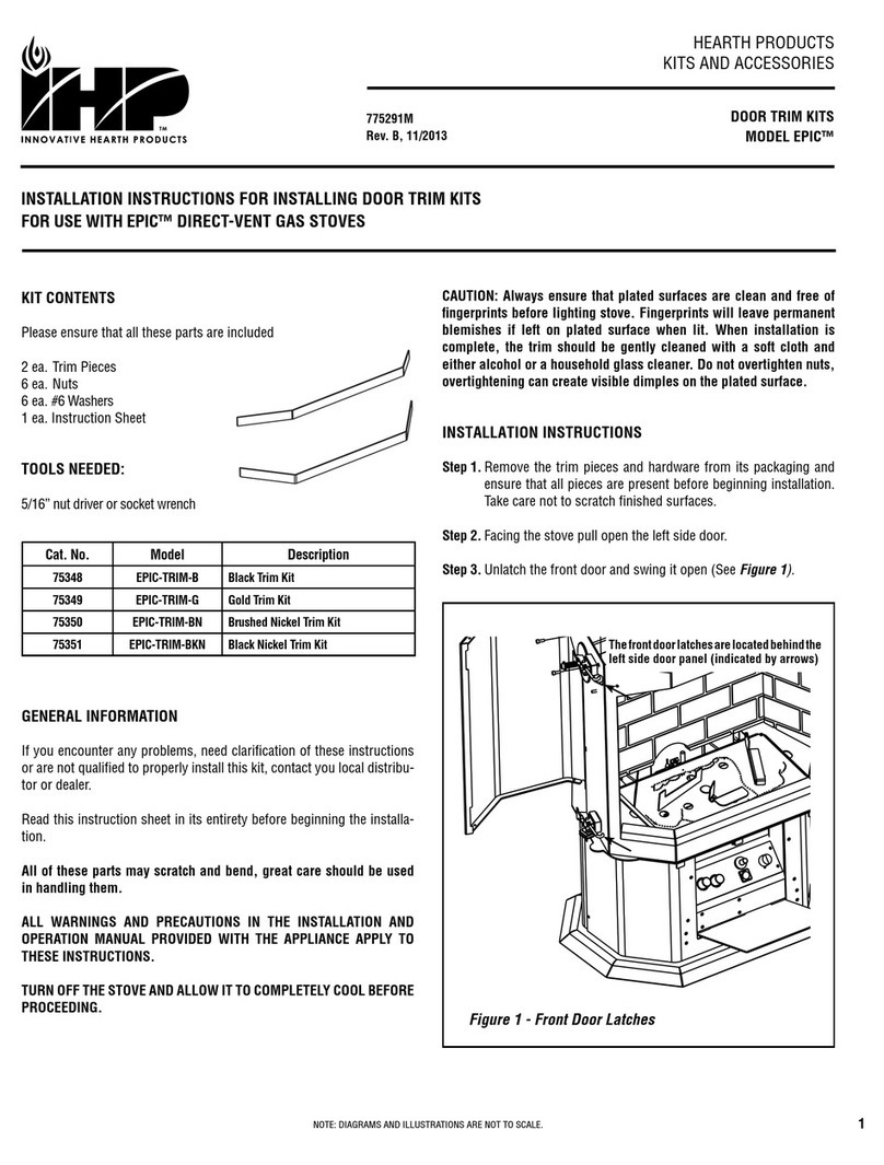
IHP EPIC-TRIM-B User manual

IHP

IHP EPIC-TRIM-B User manual

IHP DUALBURNER24N User manual

IHP

IHP DUALBURNER24N User manual

IHP Superior 900347-00 User manual

IHP

IHP Superior 900347-00 User manual

IHP WINSLOW PS40 User manual

IHP

IHP WINSLOW PS40 User manual

IHP AK4 User manual

IHP

IHP AK4 User manual

IHP GAB Series User manual

IHP

IHP GAB Series User manual

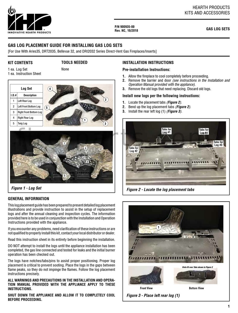
IHP 900935-00 User manual

IHP

IHP 900935-00 User manual

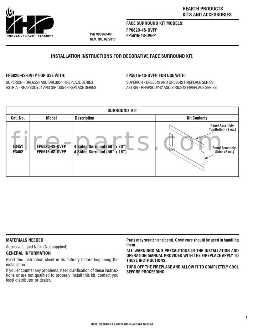
IHP FP6820-4S-DVFP User manual

IHP

IHP FP6820-4S-DVFP User manual

IHP BLB36SF Series User manual

IHP

IHP BLB36SF Series User manual

IHP BWBK User manual

IHP

IHP BWBK User manual

IHP H5872 User manual

IHP

IHP H5872 User manual

IHP VF F3784 User manual

IHP

IHP VF F3784 User manual

IHP Snap-Pak User manual

IHP

IHP Snap-Pak User manual

IHP DEL SOL User manual

IHP

IHP DEL SOL User manual

IHP PCBE-36 User manual

IHP

IHP PCBE-36 User manual

IHP PCBE-324 User manual

IHP

IHP PCBE-324 User manual

IHP Montebello Series User manual

IHP

IHP Montebello Series User manual

IHP Astria Series User manual

IHP

IHP Astria Series User manual

IHP BNZN User manual

IHP

IHP BNZN User manual

IHP FBK-LIN User manual

IHP

IHP FBK-LIN User manual

IHP PCBE-325 User manual

IHP

IHP PCBE-325 User manual

IHP BVCBK User manual

IHP

IHP BVCBK User manual

IHP FP4125-BDVI32 User manual

IHP

IHP FP4125-BDVI32 User manual

IHP CDFBBK-35 User manual

IHP

IHP CDFBBK-35 User manual

Popular Fireplace Accessories manuals by other brands

Valor L2 1700K quick start guide

Valor

Valor L2 1700K quick start guide

Exodraft Xzense manual

Exodraft

Exodraft Xzense manual

Whalen Ruso MNFP62BF23-6 manual

Whalen

Whalen Ruso MNFP62BF23-6 manual

Woodstock Soapstone Fireview 201 manual

Woodstock Soapstone

Woodstock Soapstone Fireview 201 manual

EdilKamin SERBATOIO 250 Installation, use and maintenance

EdilKamin

EdilKamin SERBATOIO 250 Installation, use and maintenance

Bronpi KIT-1 instructions

Bronpi

Bronpi KIT-1 instructions

Town & Country Fireplaces 22150051 instructions

Town & Country Fireplaces

Town & Country Fireplaces 22150051 instructions

Travis Industries 33 DVI installation instructions

Travis Industries

Travis Industries 33 DVI installation instructions

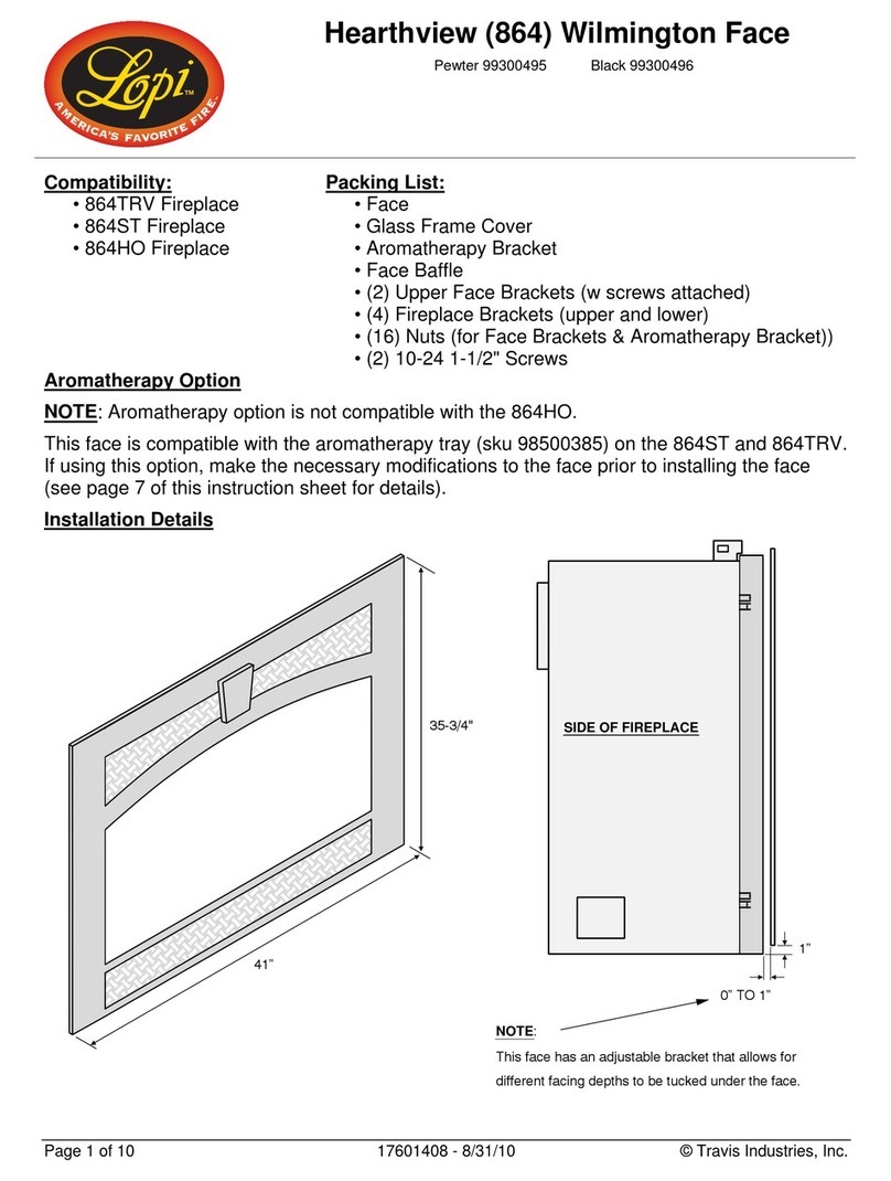
Lopi Hearthview 864 user manual

Lopi

Lopi Hearthview 864 user manual

Lennox Hearth Products LENNOX MPE-33R installation instructions

Lennox Hearth Products

Lennox Hearth Products LENNOX MPE-33R installation instructions

Dimplex DFP6776C install guide

Dimplex

Dimplex DFP6776C install guide

Napoleon W175-0689 instruction manual

Napoleon

Napoleon W175-0689 instruction manual

Travis Industries 95400424 installation instructions

Travis Industries

Travis Industries 95400424 installation instructions

Osburn ZERO CLEARANCE KIT installation instructions

Osburn

Osburn ZERO CLEARANCE KIT installation instructions

Majestic QUARTZPLA36IN installation instructions

Majestic

Majestic QUARTZPLA36IN installation instructions

Napoleon DBPO36 installation instructions

Napoleon

Napoleon DBPO36 installation instructions

Dimplex SMP-130-E install guide

Dimplex

Dimplex SMP-130-E install guide

Empire Comfort Systems LS50TINF installation instructions

Empire Comfort Systems

Empire Comfort Systems LS50TINF installation instructions

manuals.online logo
manuals.online logoBrands
  • About & Mission
  • Contact us
  • Privacy Policy
  • Terms and Conditions

Copyright 2025 Manuals.Online. All Rights Reserved.

NOTE: DIAGRAMS & ILLUSTRATIONS ARE NOT TO SCALE.
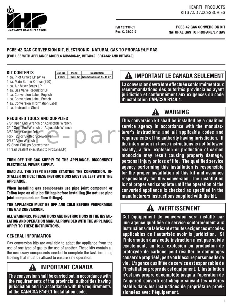
HEARTH PRODUCTS
KITS AND ACCESSORIES
750206M
REV. B 05/2017
TOOLS / SUPPLIES REQUIRED
• 5/16” Nut driver or Socket • Duct Tape • Silicon Type Caulking
GENERAL INFORMATION
This kit is for use with various IHP vent-free fireboxes when installed in
conventional construction. These kits have an air gate assembly which allows
adjustment of the amount of outside air delivered to the fire for combustion.
Only one air kit, located on the right side of the firebox, is required.
READ ALL THE STEPS BEFORE STARTING THE INSTALLATION
THE FIREPLACE MUST BE OFF AND COLD BEFORE BEGINNING.
ALL WARNINGS, PRECAUTIONS AND INSTRUCTIONS IN THE
INSTALLATION AND OPERATION MANUAL PROVIDED WITH THE
APPLIANCE APPLY TO THESE INSTRUCTIONS.
If you encounter any problems, need clarification of these instructions
or are not qualified to properly install this kit, contact you local distribu-
tor or dealer.
If any of these parts are missing or damaged, contact your dealer or IHP.
us.com for referral information.
Retain These Instructions for Future Reference
INSTALLATION INSTRUCTIONS
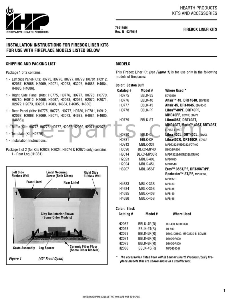
1. Remove the outside air knock-out on the right hand side of appliance
(See Figure 2 for location).
2. Assemble the Air Gate as shown in Figures 3 and 4.
3. Take the Air Gate Assembly and feed the arm through the round opening
(see Figures 5 and 6)and then through the side frame opening. Ensure
the air gate arm remains attached to the air gate (see Figure 7).
Figure 1 - Kit Contents (see Table 1)
1
1
651
7
4
23
Remove Outside
Air Knock-Out
Right Hand Side
of Firebox
Figure 2
Side View of Arm
installed into Air
Gate.
Air Gate Assembly
Air Gate Arm
Figure 3
When assembled onto appliance, the notch
here must be positioned down as shown.
Outside View of
Arm installed
into Air Gate.
Air Gate Arm
Air Gate
Figure 4
WARNING
Do not operate the combustion air gate with a fire in the firebox
unless all components of this kit have been installed.
Air Gate Arm
Figure 5
Right Side
Panel on
Firebox
Air Gate
US
Outside Air Gate & Duct Kit
Cat. No. Model Description
H3991 OAK-UVFRC Outside Air Gate & Duct Kit
KIT CONTENTS
1 ea. Air Gate Assembly (1)
1 ea. Arm, Air Gate (2)
1 ea. Bracket, Air Gate Arm (3)
1 ea. Collar, Outside Air (4)
1 ea. Duct, 4” (5)
1 ea. Hardware Kit (9 long screws & 4 short screws) (6)
1 ea. Instruction Sheet (7)
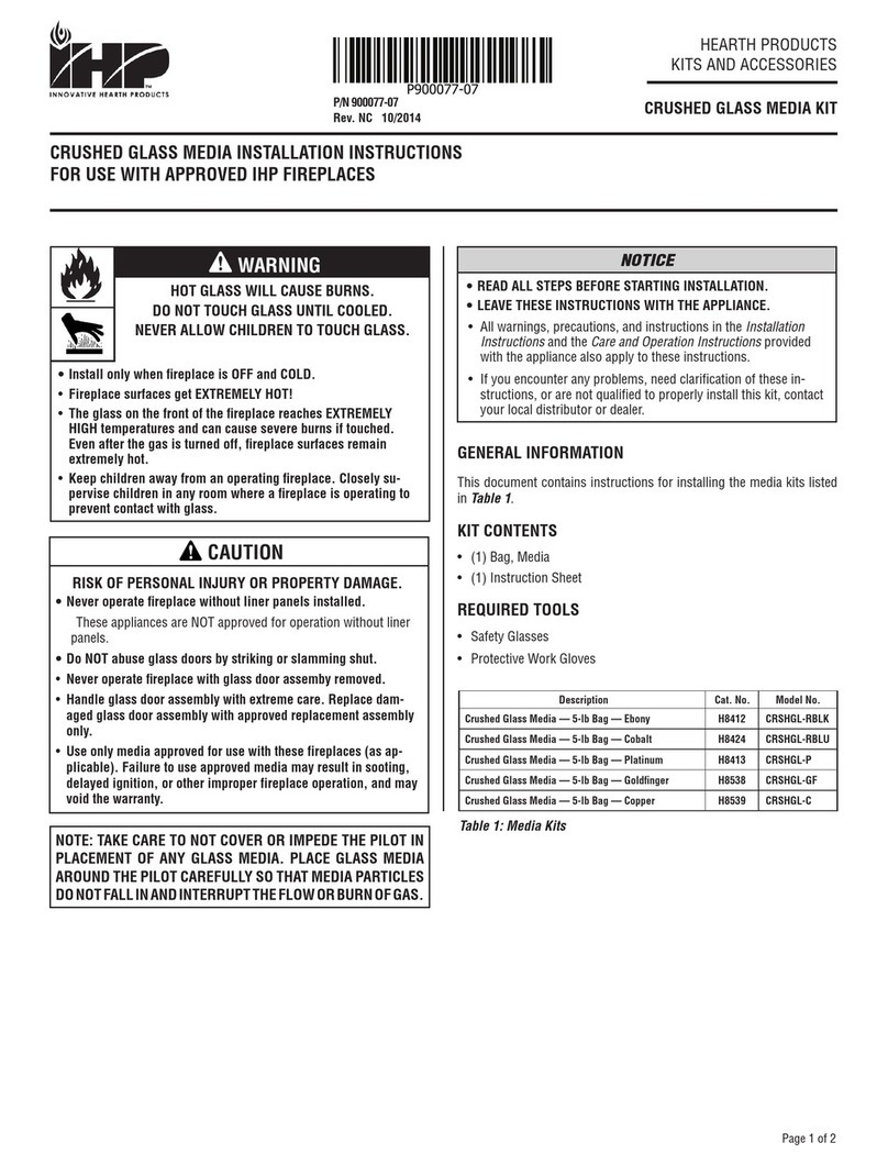
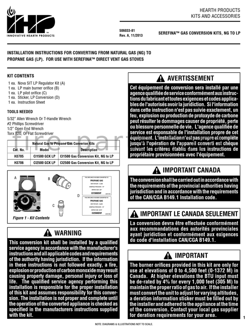
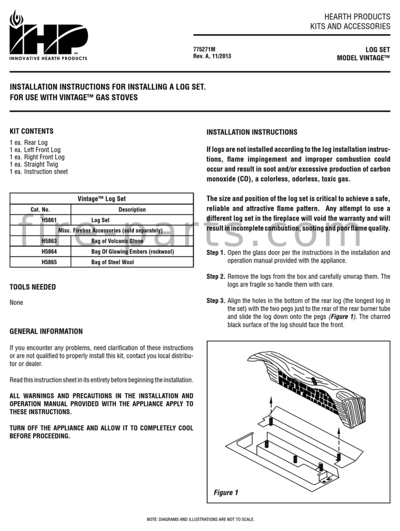
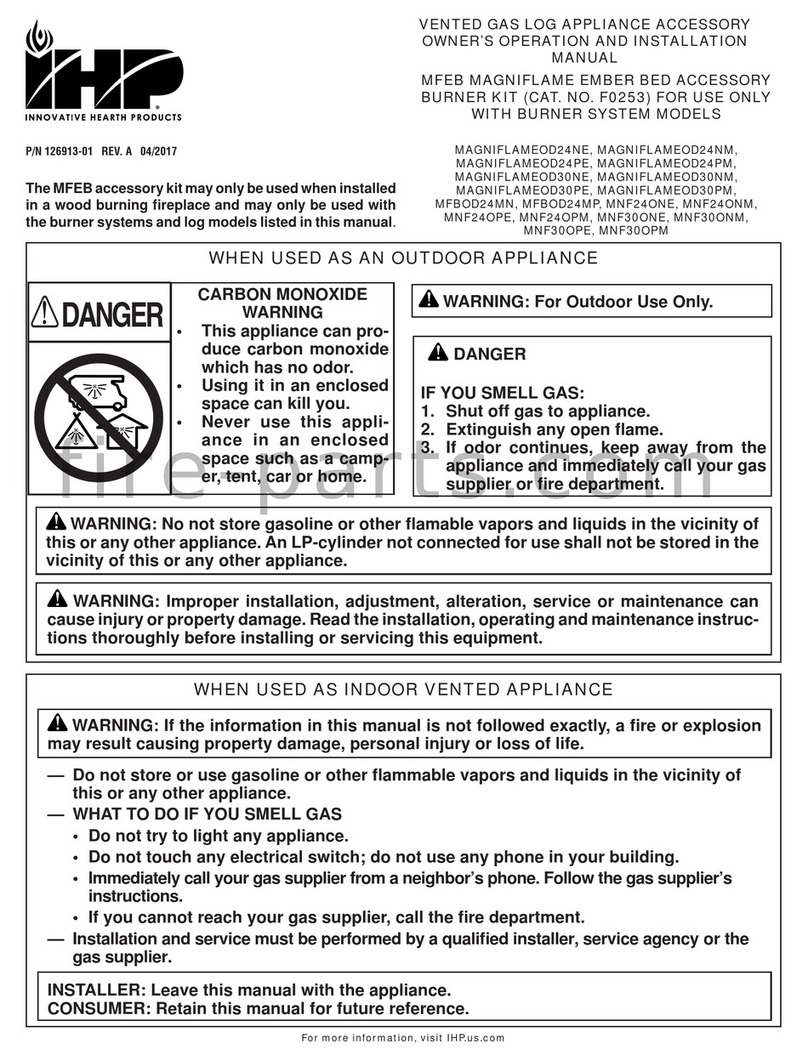
OAK-UVFRC OUTSIDE
AIR GATE & DUCT KIT
OAK-UVFRC OUTSIDE AIR GATE & DUCT KIT
[FOR USE WITH MODELS ATLAS36/42, ORION32/36/42, VRT2536/42, VRT3132/36/42, VRT3536/42, AND VARIOUS LHP LEGACY APPLIANCES]
fire-parts.com
2
5. Secure the air gate arm support bracket (item
#3 in Figure 1) as shown in Figure 9.
4. Secure the air gate to the firebox as shown
in Figure 8.
7. Attach flexible duct to the outside air collar
using two (2) short screws (provided), then
wrap with duct tape as shown in Figure 11.
Printed in U.S.A. © 2006 Innovative Hearth Products
P/N 750206M REV. B 05/2017
NOTE: DIAGRAMS & ILLUSTRATIONS ARE NOT TO SCALE.
Hold the air gate arm and align the air gate assem-
bly to fit flush in the opening.
Figure 6
Figure 12
8. Duct Hole Framing: Cut or frame a hole through
the outside of the enclosure for the installation
of the duct inlet hood. A 5" (127 mm) diameter
hole is required. Feed the loose end of the flexible
duct through the hole cut for the inlet hood and
attach to the collar on the inlet hood using two
(2) short screws (provided), then wrap with duct
tape. Insert the hood into the opening. Secure in
place with nails driven through the holes in hood
flange. Seal with noncombustible waterproof
silicon type caulking. If additional duct is needed,
use Class 0 metallic air duct (refer to Figure 12).
NOTE: The Class 0 metallic air duct can be routed
out the back wall or side wall, up through the ceiling
or floor joists to an outside wall. Check local build-
ing codes for any restrictions. We recommend that
the inlet be at least four (4) feet above grade level.
4" (102 mm)
Class 0 air duct
Hood
Air Inlet
Secure the hood
to a vertical post
with the inlet posi-
tioned downward.
• IN COLD CLIMATES
THE AIR DUCT SHOULD
BE INSULATED.
CAUTION
Do not install the air inlet in the attic,
garage, near combustible gases (i.e.
paint, gasoline, etc.) or where there
is a fuel burning appliance or where
the opening could be blocked by snow,
bushes or other obstacles.
6. Secure the outside air collar (item #4 in Figure
1) as shown in Figure 10.
Innovative Hearth Products
1508 Elm Hill Pike, Suite 108 • Nashville, TN 37210
IHP reserves the right to make changes at any time, without notice, in design, materials, specifications, prices and the discontinuance of colors, styles and products. Consult your local distributor
for fireplace code information.
Air Gate Arm
Front right
side of firebox
opening
Locate this opening
Feed the bent end of the air gate arm
into this notched opening.
Figure 7
OPEN POSITION
CLOSED POSITION
Air
Gate
Secure the Air Gate to the fireplace with four
(4) long screws (provided) through the outside
holes (indicated by arrows).
Right Side
of Firebox
Figure 8
Ensure this
notch is
positioned
on the
bottom half
of air gate.
Locate this slot on right
side panel of firebox.
Slot
Insert the arm support bracket as shown.
Adjust arm as necessary to rest on the bracket
Slot
Bracket
Secure the
bracket with a
screw provided.
Long
Screw
Figure 9
Bracket
Outside
Air
Collar
Secure the outside air collar over the air gate
using the four (4) long screws (provided)
through the inside holes (indicated by arrows).
Figure 10
Collar
Secure the duct to
the collar using
duct tape as
shown.
Figure 11
fire-parts.com