SEM 5500TX User manual

Coin Timer
for
Campground Shower
and other
Multiple Uses
July 2017 # i01741

2
Introduction
We thank you for purchasing the Coin timer Model 5500TX. This device will
allow you controlling multiple applications such as a campground shower, a
tennis court lighting*, a car-wash vacuum cleaner*, or any other device requir-
ing payment based on time.
The 5500TX is an enhanced version of our model 5500TS. The added fea-
tures are an LCD display and a multi-coin electronic acceptor allowing to use
any coins. The display also offers a full audit.
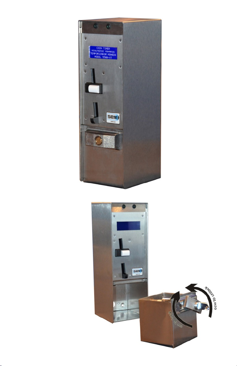
The housing of the 5500TX offers an added protection against vandalism
compaRed to the previous Model 5000. The coin box was designed so that
you do not need to remove the full face plate to access the money.
We believe this device will provide you with good service for many years to
come with a minimum of care. If you have any questions, do not hesitate to
contact us. Our service department is open from Monday to Friday, from 8AM
till 4:30PM (Eastern Standard Timer) or by email at support@sem.ca
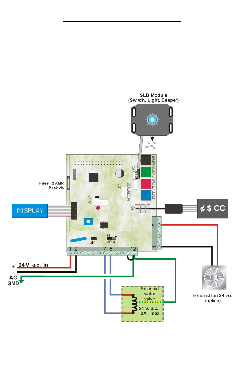
A tennis court lighting, a car-wash vacuum cleaner, or any other high-
voltage devices require adding an external relay (not included) as the con-
tacts in the timer cannot withhold high voltage. The external relay is acti-
vated by the timer, which in turn activates the high-voltage device.

3
The 5500TX closed…
...and with its coin box re-
moved; counter clockwise
to open, clockwise to
close...

4
Installing your timer
Use the proper anchoring system depending the type of wall your have. It is
your responsibility to make sure nobody can rip the timer off the wall.
Make sure elec-
trical connec-
tions meet the
local electrical
code. If you are
not familiar with
electricity, do not
hesitate to con-
tact a certified
electrician to
avoid electrical
shocks and dam-
ages to the
timer.

5
Description of the 5500TX circuit
The circuit of the 5500TX is located in the top right side of the internal housing
and divides in two sections.
1. Connection for the SLB Module (Switch, Light, Beeper) 4 wires.
2. Connection for the mechanical coin acceptor.
3. Connection for the electronic coin acceptor (MDB).
4. Micro-chip containing the entire memory (parameters and audit).
5. Connection for auxiliary terminal block (6 screws).
6. Connection for main terminal block (12 screws).
7. Location of Jumper JP1 (absent on the image).
8. MCU red flashing LED.
9. Intensity adjustment for Blue display.
10. Connection for portable printer with proper adapter.
11. Connection for blue LCD display.
12. Fuse 2A 250 volts 2cm (not visible) on the main circuit.
13. Extension board piggybacked on the main circuit.

6
Description of the main and auxiliary terminal blocks
There are two terminal blocks on the circuit: one horizontal 12-screw and one
vertical 6-screw. Both can be removed from the circuit. They may be hard to
remove and that is normal as we do not want them to disconnect themselves
under the effect of their own weight.
There is no indication on the block itself. Therefore, the image below will
serve you as reference. On the big block, number 1 is on the left. The big
block has 12 screws.
1. 24vac In.
2. 24vac In.
3. n/a
4. n/a
5. Dry contact NC (if jumper JP1 is REMOVED).
6. Dry contact C (if jumper JP1 is REMOVED).
7. Dry contact NO (if jumper JP1 is REMOVED).
8. 24vac output (if jumper JP1 is IN PLACE).
9. n/a
10. n/a
11. Accept Line Switch in your device (if applicable).
12. Ground. Jumped to 11 if there is no Accept Line Switch in your machine
as visible on the image.
On the small block, number 1 is a the bottom. The small block has 6 screws.
6. n/a
5. Output + 24vdc auxiliary (i.e.: exhaust fan)
4. n/a
3. n/a
2. n/a
1. Output - 24vdc auxiliary

7
Typical wiring for a campground shower
This diagram shows the timer with an electronic multiple-coin acceptor and the
SLB Module (Switch, Light, Beeper). The timer controls a water valve in a
campground shower. The payment peripherals could be coins only, coins &
bills, or coins, bills & credit card. The type of peripheral will not affect the wir-
ing. There is also a small auxiliary output for an optional exhaust fan. Pins 12
& 11 are linked as there is no Accept Line Switch.

8
Programming your timer
The 5500TX timer is equipped with an LCD display allowing you to navigate
easily in the programming. The four buttons on the circuit are:
Black To scroll all the menus.
Green To access the menu visible on the display.
Red To modify the current setting or increase a number.
Blue To modify the current setting or decrease a number.
Operator Mode
There are five menus accessible to any person opening the timer.
Audit Gives you the accounting information
Currency setting Allows you to decide which money to accept
Session length Defines the length of the time session
Session rate Defines the cost of the timer session
Session mode Defines timing style
Technician Mode
There are two menus accessible in a hidden access.
System setting Programming the secondary parameters
Test Mode Not available at the time of printing

9
Retrieving the accounting information
The X25TX circuit of the Model 5500TX offers you a full accounting descrip-
tion on sales and the money accepted. Press the Black button once. When
AUDIT is visible on the display, press on the Green button. Then press on the
Black button to scroll through the information (see flow chart below). The
quantity of information available varies depending the payment peripherals
attached to the X25TX controller. As an example, if you have a coin changer,
you will then see the coin tube inventory. A bill acceptor will also bring you
different information the same if a card reader is attached.
Many counters are double. In such a case, one can be erased, the other no.
The abbreviation Cumul: indicates a cumulative non-erasable counter.
Note the last line of the display indicates you what button to use and the ac-
tion resulting of it.
Insert coins
$1.00 / 4m
Audit
Black = next,
Coin box:
28.75$
Black = next,
Currency setting
Green = to enter,
Insert coins
$1.00 / 4m
Cash sales:
28.75$
Holding green = print
Cash sales:
Cumul. 59.50$
Black = next,
Total sales:
59.50$
Black = next,
Total sales:
Cumul. 59.50$
Black = next,
Sales aux. pulse:
$0.00
Black = next,
Operator Mode
In all cases, the last line of the display indicates
the buttons that can be used and their function.
Sales aux. pulse:
Cumul. $0.00
Black = next,
Aux. Pulse number:
0
Black = next,
Aux. Pulse number:
Cumul. 0
Black = next,
Time sold:
H:mm:ss 0:05:05
Black = next,
Time sold
Cumul. 3:58:00
Black = next,
Reset meters ?
Hold RED button
Black = exit

10
Programming your timer
There are two sections for programming your timer:
Operator Mode
Technician Mode
The Operator Mode offers the accounting information as seen previously, the
settings for the currency to accept, the time a session lasts, the rate of that
time sessions, and finally the session style.
As for the Technician Mode, it allows programming parameters that are more
technical and should be access by a competent person. As a matter of fact,
accessing this section cannot be accidental. If you access this section it is
because you want to access it.
You will find on the right the flow chart allowing you to navigate through the
Operator Mode. In the following pages are the explanation of each parame-
ters and the possible choices available to you.

11
Red = increase; blue = decrease; green = mode digit
Insert coins
$1.00 / 4m
Audit
Black = next,
Scrolls through the
entire audit
Currency setting
Green = to enter,
Currency setting
0.05$ coin no
Red = to modify,
Scroll through the
entire coin set
Session length
Green = to enter,
Session length
hh:mm:ss 00:04:00
Green = to save,
Red = increase; blue = decrease; green = mode digit
Session rate
01.00$
Green = to enter,
Session mode
Green = to enter,
Session mode
Cash: continuous
Red = to modify,
Minimum charge
01.00$
Green = to save,
In all cases, the last line of the display indicates
the buttons that can be used and their function.
Saving, one moment
please
Session rate
01.00$
Green = to save,
Insert coins
$1.00 / 4m
Preset charge
01.00$
Green = to save,
Saving, one moment
please
Session mode
Cash: preset
Red = to modify,
Operator Mode
Yes or no

12
Currency setting
You can decide here what currency you wish your timer to accept (coins or
bills). At power up, the peripherals detected will send their internal configura-
tion to the circuit. From there, you can decide to accept or not the currency.
In the Timer 5500TX, there is only a coin acceptor as you cannot fit a coin
changer or a bill acceptor.
Press the Black button until Currency setting is visible. Press on the Green
button to enter. The display will most likely show $0.05 coin YES (accepts 5¢
or NO (rejects 5¢). Press on the Red button to modify the setting. Press on
the Green button to confirm the setting and move to the next currency. Re-
peat for all coins.
Session length
This is where you program the length of a time session. The maximal time a
session can last is 99 hours, 59 minutes and 59 seconds. When Session
length is visible on the display, press the Green button and it will show the
current setting (i.e.: hh:mm:ss 00:04:00). Note the first digit is blinking. Press
on Red to increase this digit of Blue to decrease. Once the good value
reached, press the Green button to move digit. Repeat the process until all
digit are programmed.
Session rate
This is where you program the price of the time session you just programmed
on the previous step. When visible on the display, press the Green button
and the current rate will be visible with the first digit blinking. Press on Red to
increase this digit of Blue to decrease. Once the good value reached, press
the Green button to move digit. Repeat the process until all digit are pro-
grammed.
This is the rate on which the timer will be calculated according the money in-
serted.
Session Mode
You have the choice between Continuous or Preset. When Session mode is
visible on the display, press on the Green button to see the current setting.
Press on Red to modify it.
In the case of the Continuous mode, it is possible to stop the time and get a
refund of the unused portion of time paid if there is a coin changer in the timer.
In Preset, the time bought must be consumed till the end. As there is no pos-
sibility to install a coin changer in the Coin Timer 5500TX, needless to pro-
gram Continuous as no change can be given out.

13
After that, you must program an amount that will be a minimum amount re-
quired to start a time session. The amount programmed here does not need
to be equal to the rate session. You can have a rate session of $2 but require
only $1 to start the time session. Obviously, this $1 inserted will equal half the
time programmed in session length. (i.e.: rate session $2; session length 2
minutes ; $1 inserted = 1 minute bought).
This concludes the Operator Mode.

14
Insert coins
$1.00 / 4m
System setting
Black = next,
Language
Green = to enter,
Test mode
Black = next,
Insert coins
$1.00 / 4m
Hold both
for 3
seconds
In all cases, the last line of the display indicates the buttons that can be
used and their function.
Choices available are showned above each parameter.
Technician Mode
Under
construction
Machine ID
Green = to enter,
Beeper loudness
Green = to enter,
Rate vs Time display
Green = to enter,
Auxiliary Acc type
Green = to enter,
PAUSE limit time
10 minutes
Green = to enter,
Choice of letter and
number Level 0 to 10
Yes or no None, coin, token
00 mm
Warning 1
Green = to enter,
Warning 2
Green = to enter,
Aux Output time
Green = to enter,
mm:ss 00:00 15 seconds mm:ss 00:00
Minimum charge
chrono
Green = to enter,
Message
* Welcome *
Green = to enter,
Message
* Out of order *
Green = to enter,
30 seconds
Four lines of message
available
Four lines of message
available
Print parameters
Green = to enter,
Start Function
Green = to enter,
Pause Function
Green = to enter,
Auto, manuel, ctrl
externe Yes or no
Aux. Pulse value
01.00$
Red = to increase,
None, coin, token

15
The Technician Mode is reserved for person having a technical skill. You can-
not access this section by accident. To access it, press AND hold both the
Red and Blue buttons for at least three seconds.
This section divides in two menus:
System setting
Test mode (still in development)
System setting:
The is where you will program some very specific parameters of your timer.
Use the programming flow chart to the left to help you navigate in the parame-
ters.
Language
The timer can display in English or in French but not both at the same time.
When visible on the display, press on the Green button to see the current set-
ting. Press on the Red button to modify it and Green to confirm your new set-
ting.
Machine ID
If you are operating a fleet of timers, you can apply a specific ID to each of
them. You can have numbers and letters as well as some special characters
like ? or >. When visible on the display, press on the Green button and the
first available space will blink. Press on the Red or Blue button to reach the
desired character. Press on Green to move digit. If you keep the Green but-
ton depressed, you will go back to the precious character. This machine ID
will be visible at the top of each audit print-out.
Beeper loudness
This is where you will program the volume of the beeper located into the SLB
Module. This beeper beeps 5 times when the remaining time is 30 seconds
and for the last 15 seconds bought. There are 10 sound levels with level 0
being mute.
Rate vs time display
You can show or not the rate on the timer. The display will then toggle be-
tween the coins accepted (i.e.: 25¢, $1 & $2), the minimum deposit (i.e.: Mini-
mum deposit $0.50) if any, and the rate (i.e.: 1.00$ */ 4m). If you set it to
NON, the rate will not be displayed.

16
Auxiliary Acc type:
It is possible to add an auxiliary acceptor to the main acceptor. In such a
case, you need to instruct the timer if it is a coin acceptor, a token acceptor or
NO acceptor at all. We are talking here about a mechanical-type acceptor that
will send one pulse at the passage of a coin or a token.
Auxiliary pulse value:
At the previous step, you have selected the type of auxiliary acceptor.,
either coin or token. Here you will instruct the timer about the value
each pulse generated by te passage of the coin or token. Press on
the Green button to see the current value. Note the first digit is blink-
ing. Press on Red or Blue to modify the digit and Green to move digit.
Repeat the process for all digits. To move back, press and hold the
Green button.
Start function:
You have three ways to operate your timer: Automatic, manual, or external
control. The automatic mode starts a 5-second countdown once the minimum
amount deposited and the display will show the amount and the time it gives.
The manual mode requires the SLB module (Switch, Light, Button) and allows
remote start. The External control will start the time through an external con-
trol device that will simulate someone pressing on a start button. If you have
no SLB Module nor External control, you must then select Automatic start.
Pause function:
If you have selected Manual start, you can allow the user to pause the
time while in use. Select Yes or No.
PAUSE time limit:
This parameter allows to program a maximum pause time at the end
of which the timer will presume the customer has left and will then
cancel the remaining paid time. Here is an example of how it works.
The customer buys a 5-minute usage. After three minutes of use, he
presses on Pause. An hidden countdown will then start. When the
time limit will be reached (i.e. 10 minutes) the timer will start a 30-
second warning countdown on the display with beeps warning the
customer to restart the time. If the customer does not restart the
timer, what's left of the time session (2 minutes) will be lost. This
process repeats itself on every pause.

17
Warning 1
The timer offers two end-of-time warnings if you have the SLB module. The
moment those warning will active is programmable here. The first warning last
for 5 seconds only et will start at the moment you program here (i.e. 00:30).
Therefore, when the time left reaches 30 seconds, the beeper will sound 5
times.
Warning 2
The second warning will last for the time you program here and last till the
very end of the time cycle. If you program 15 seconds, the beeper will sound
for the ultimate 15 seconds.
Aux. Output time:
The timer has an auxiliary output that will activate at the very end of the cycle
and last for the timer programmed here. This output is located on the 6-screw
auxiliary terminal block, at positions 1 and 5. A perfect example would be an
exhaust fan expulsing humidity outside the shower. The maximum time it can
run is 30:00. Note that the output voltage is 24vdc (see page 6).
Minimum charge chrono
Minimum Charge chrono is grace period following a time cycle where a cus-
tomer can add credits to the timer without having to insert the minimum
charge. This delay only applies if the timer has been set to Continuous in the
Session mode (see page 12). The maximum time is 5 minutes or 300 sec-
onds.
Message *Welcome*
It possible to program a personalized welcome message that will be visible on
the 4-line display, alternating with the default messages. Each line has 20
characters, including spaces. Therefore, this message Welcome to camping
has 18 characters. Use the Red or Blue buttons to navigate through the many
characters available. They include accents, low-case and high-case letters
and numbers.
Message *Out of order*
It possible to program a personalized welcome message that will be visible on
the 4-line display, if the timer goes out of order. Each line has 20 characters,
including spaces. Therefore, this message Contact Front Desk has exactly 18
characters.

18
Print parameters:
It is possible to print all the parameters on a small portable serial printer avail-
able in option from SEM. This print-out is very useful if you have a fleet of
timer to program. Note that this printer is the same you can use to print the
audit (see page 9).
This concludes the System setting section.

19
SEM INC. –WARRANTY AND LIABILITY CONTRACT
By issuing a Purchase Order or contracting with SEM Inc. to
carry out the supply of products, clients are accepting the terms
of this Warranty and Liability Contract.
SEM Inc. warrants all parts of new equipment for one (1) year, from
date of invoice against DEFECTIVE MATERIAL OR WORKMAN-
SHIP, but not against damage caused by accident, abuse, faulty in-
stallation, or improper operation and installation.
SEM Inc. shall not be liable for any direct, indirect and/or conse-
quential damages or losses, including loss of use, revenue, profit
incurred by the client, its customers and/or any third party as a result
of the use of the work carried out by SEM Inc. for the client, includ-
ing any loss resulting from equipment failure or malfunctions, design
or programming errors or any other use of the work carried out in
this contract. The client specifically waives any claim or recourse it
may have against SEM Inc. in any of the above instances.
SEM Inc.’s obligation under this warranty is limited to correcting, or
at its option replacing, without charge at its factory any equipment,
components or parts thereof which are returned to its factory
(transportation charges prepaid) within one year after date of invoice,
examination of which disclose to SEM Inc.’s satisfaction that the
equipment, components, or parts thereof were originally defective.
Any changes in design or improvements added to the line of equip-
ment shall not create any obligation to upgrade or modify equipment
previously sold and delivered to the client.
Any unauthorized alteration of, or addition to, articles of the contrac-
tors manufacture voids this warranty.
Equipment or components returned for Warranty repair must
be accompanied by a copy of the original invoice as verification
of purchase date. Equipment or components returned without a
copy of original invoice will be charged to the customer at the
regular repair rates.

20
This manual was written by our technical department. Even though the ut-
most attention was given to writing this manual, errors may have slipped by
unnoticed. Any comments, suggestions, or errors should be sent directly to:
info@sem.ca
Telephone: 1-514-334-7569 Fax: 1-514-334-5922
Table of contents