Example:Humidification
Control=80%RH *Timeon=20sec
Hysteresis=5%RH *Timeoff=10sec
Whenhumidityfallsto75%RH(80-5),thehumidistatoutputstartstocycle:20sec.on-10sec.Off
F01-
F02-
F03-Minimumsetpointallowedtotheenduser(t
It is necessary to change the configuration parameters. To visualize the adjusted parameters, it is not
necessarytoinsertthisaccesscode.
0-Refrigeration
1-Heating
Accesscode:123(onehundredandtwenty-three)
hermostatoperationmode(THERMoutput)
hermostat)
T
F04-Maximumsetpointallowedtothe enduser(thermostat)
F05-Controldifferential(hysteresis)ofthethermostat
F06-Minimumdelaytoturnthethermostatoutputon
F07-Humidistatoperationmode(HUMIDoutput)
Itistopreventthatincorrecthighorlowtemperaturesberegulated.
Itisthedifferenceoftemperature(hysteresis)betweenONandOFFtheTHERMoutput.
Itis theminimumtimethatthethermostatwill keepturned off,itmeans,thespace oftime betweenthe
laststopantthenextstart.
0-Dehumidification
1-Humidification
F08-Minimumsetpointallowedtotheuser(humidistat)
F09-Maximumsetpointallowedtotheuser(humidistat)
F10-Controldifferential(hysteresis)ofthehumidistat
F11-M
F12-
F13-
Electroniclimitswhosepurposeispreventthattoohighortoolowsetpointhumiditysareregulated.
Itisthedifferenceofhumidity(hysteresis)betweenturnONandturnOFFtheHUMIDoutput.
Itis theminimumtime thattheHUMID outputwill keep turnedoff, itmeans, thespaceof timebetween
thelaststopantthenextstart.
ItallowstoadustthetimethatHUMIDoutputwillkeepturnedon.
ItallowstoadustthetimethatHUMIDoutputwillkeepturnedoff.
inimumdelaytoturnthehumidistatoutputon
Humidityoutput(timeon)
Humidityoutput(timeoff)
Note:F12andF13functionscontrolacyclicalprogram(inseconds)forthehumidistatoutput.
Thiscyclicalprogramallowsthatpulverizedwaterhastimetotransforminrelativeairhumidity.
Todisablethisfunction,adjustthenwithvalue“00.0”.
F14-Auxiliaryoutputoperationmode(AUX)
F15-Minimumsetpointallowedtotheuser(AUXoutput)
F16-Maximumsetpointallowedtotheuser(AUXoutput)
F17-Controldifferential(hysteresis)oftheAUXoutput
F18-MinimumdelaytoturntheAUXoutputon
0-Refrigeration
1-Reating
2-Dehumidification
3-Humidification
4-Intra-rangealarm
5-Extra-rangealarm
When changing the value of this function the following parameters will be automatically adjusted with
theirdefaultvalues:F15,F16,F17andsetpointfortheAUXoutput.
Electroniclimitswhosepurposeispreventthattoohighortoolowsetpointvaluesareregulated.
ThelimitswilldependontheoperationmodeoftheoutputadjustedinF14.
It is the difference of temperature or humidity (hysteresis) between turn ON and turn OFF the AUX
output.ThisfunctiondependsontheoperationmodeoftheoutputadjustedinF14.
ItistheminimumtimethattheAUXoutputwill keepturnedoff,itmeans,thespaceof timebetweenthe
laststopantthenextstart.
Thistimeisvalidonlywhen AUXoutputwillbeconfiguredinthecontrolmode(F14configuredin0,1,2
or3).
ItallowstoadustthetimethatAUXoutputwillkeepturnedon.
ItallowstoadustthetimethatAUXoutputwillkeepturnedoff.
Temperatureforactivationofthel
Temperatureforactivationofthehigh
Humidityforactivationofthel humidity
Humidityforactivationofthehighhumidity
F19-
F20-
F21-
F22-
F23-Lowroomhumidityalarm
F24-Highroomhumidityalarm
AUXoutput(timeon)
AUXoutput(timeoff)
Lowroomtemperaturealarm
Highroomtemperaturealarm
owtemperaturealarm.
temperaturealarm.
ow alarm.
alarm.
F25-MinimumdelaytoturntheAUXoutputon(alarmmode)
ItistheminimumtimethattheAUXoutputwill keepturnedoff,itmeans,thespaceof timebetweenthe
laststopantthenextstart.Thistimeisvalidonlywhen AUXoutputwillbeconfiguredinthealarmmode
(F14configuredin4or5).
F26-Buzzeroperationmode
F27-ActingpointoftemperatureBuzzer(inferiorlimit)
F28-ActingpointoftemperatureBuzzer(superiorlimit)
F29-ActingpointofhumidityBuzzer(inferiorlimit)
0-Intra-rangealarm
1-Extra-rangealarm
ItistheinferiorvalueoftemperaturetothebuzzeralarmactastheconfiguredOperationModeofBuzzer
(F26).
It is the superior value of temperature to the buzzer alarm act as the configured Operation Mode of
Buzzer(F26)
It is the inferior value of humidity to the buzzer alarm act as the configured Operation Mode of Buzzer
(F26).
F30-ActingpointofhumidityBuzzer(superiorlimit)
Itisthesuperiorvalueofhumidity tothe buzzeralarm actas theconfiguredOperationModeofBuzzer
(F26).
F31-Buzzer timeon
F32-Buzzer timeoff
F33-InhibitiontimeofBuzzerduringelectricalsupply
F34-Displaymode
F35-Temperaturedisplayoffset
ItisthetimethattheBuzzerwillbeturnedon(cycleon).Toturnitoffthesonorealarm(Buzzer)adjustthe
value“0”tothisfunction.
Itisthetime that the buzzer will be turned off(cycle off).Toturnthe sonore alarm (Buzzer) always on,
adjustthevalue“0”tothisfunction.
Itisthetimewerethealarmwillkeptturnedoffevenifinalarmcontitions.
It serves to inhibit the buzzer during the time while the system do not reaches the working control
temperature.
0-alternatedindicationoftemperatureandhumidity
1-onlyindicationoftemperature
2-onlyindicationofhumidity
It allows to compensate eventual shunting lines in the reading of temperature proceeding from the
exchangeofthesensororcablelenghtalteration.
5.FUNCTIONSWITHFACILITATED ACCESS
5.1- Registers of minimum and maximum temperature and
humidity
5.2-To visualizehumidityortemperature
Press .Willappear followedforminimumand maximumregisteredtemperatures.Afterthat
willappear andtheminimumandmaximumregisteredhumidity.
To reset the registers, keep pressed during the visualization of the minimum and maximum
registersuntilappear .
IftheF16functionisnotinthealternatingwayofvisualization(”0”)it´spossiblevisualizetemperatureor
humiditybypressingthe key.
Note:
F36-Humiditydisplayoffset
F37-Networkequipmentaddress
It allows to compensate eventual shunting lines in the reading of humidity proceeding from the
exchangeofthesensororcablelenghtalteration.
Thisisthedeviceaddressforcommunicationwith software.
Note:Youcannothavetwoormoredeviceswiththesameaddressinthenetwork.
Sitrad®
6.SIGNALLING
LedTHERMon-
LedHUMIDon-
LedAUXon-
LedBUZZon-
T
H
Auxiliar
-Irregulartemperaturesensor
-Irregularhumiditysensor
-
hermostatoutputon
umidistatoutputon
outputon
Invalidconfigurationparameters;
-Inthissituationtheoutputsareturnedoff;
-Checkwhichparametershaveinvaliddataandcorrectthemtoreturntonormaloperation.
Buzzeractivated
7.SELECTIONOFTHEUNIT(Cº/Fº)
Inorder to define the unitthatthe instrument will operatein,enter function “F01” with theaccess code
“231”and confirmwith the key. Press the keyand theindication willappear.Press
tochoosebetween or andconfirm.Afterselectingtheunitthe messagewill
appear, and the instrument will return to the function “F01”. Every time that the unit is changed, the
parametersshouldbereconfigured,sincetheyassumethe“standard”values.
SET
SET
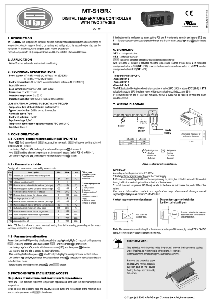
8. WIRING DIAGRAM
234567810 11 12
COMMON
THERM (NO)
HUMID (NO)
Above specified current
use contactors.
Power supply
and relays
common
0
1
Loads
supply
AUX (NO)
115V
(12V )
230V
(24V )
9-8
9-7 115V
230V
MT-531Ri plus 12V
24V
MT-531RiLplus
Loads
L3
L2
L1
- Dehumidificator
- Humidificator
- Contactor
- Solenoid
-Alarm
L3
- Dehumidificator
- Humidificator
- Contactor
- Solenoid
L2
- Contactor
- Solenoid
L1
9
White
Gray
Black
Red
Serial communication
RS-485
A
B
Temperature and
humidity sensor
Cable: SB43
Green protector
To the terminal of
the distribution box
72 mm
Dimension of the clipping for
setting of the instrument
in panel
29 mm
