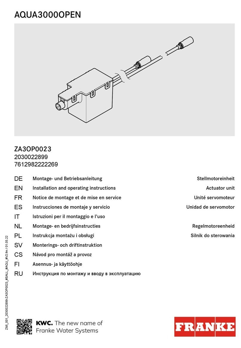
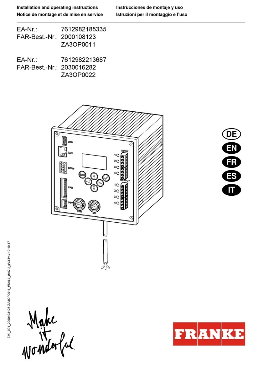
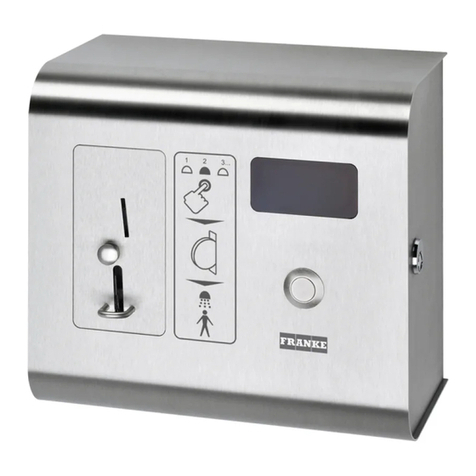
Franke AQUA802 User manual

18-05.984b-Exp.fm/12.05.11
Installation and operating instructions Montage- en bedrijfsinstructies
Notice de montage et de mise en service Montażi instrukcja obsługi
Istruzioni per il montaggio e l’uso
Franke Aquarotter GmbH
A-Nr.: 7612982130793
FAR-Best.-Nr.: 4902 08 04.......... Wertmarken
AQUA802
EA-Nr.: 7612982130809
FAR-Best.-Nr.: 4902 16 04.......... EURO 0,50
AQUA803

2
Inhaltsverzeichnis03.fm
................................................................ 3
Please refer to the graphics in the German
Installation and Operating Instructions.
................................................................ 11
Les graphiques sont disponibles dans la notice
de montage et de mise en service allemande.
................................................................ 19
Per le grafiche fare riferimento alle Istruzioni
per il montaggio e l’uso in tedesco.
................................................................ 27
De tekeningen kunt u in de Duitse montage- en
bedrijfsinstructies vinden.
................................................................ 35
Prosimy przyjąć grafikęz niemieckiej instrukcji
montażu i obsługi.

3
18-05.984b-GB.fm
0English
AQUAPAY coin-activated switch for
2 - 31 shower units, 24 V DC
7612982130793 ......... Tokens
7612982130809 ......... 0.50 EURO
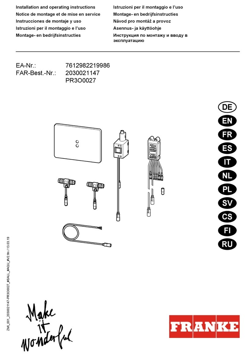
Please refer to the graphics in the German Installation and Operating Instructions.
0Table of Contents
1. Abbreviations and Units . . . . . . . . . . . . . . . . . . . . . . . . . . . . . . . . 4
2. Key . . . . . . . . . . . . . . . . . . . . . . . . . . . . . . . . . . . . . . . . . . . . . . . . 4
3. Warranty . . . . . . . . . . . . . . . . . . . . . . . . . . . . . . . . . . . . . . . . . . . . 4
4. Important Notes . . . . . . . . . . . . . . . . . . . . . . . . . . . . . . . . . . . . . . 4
Description of Product
5. Application . . . . . . . . . . . . . . . . . . . . . . . . . . . . . . . . . . . . . . . . . . 5
6. Technical Specifications . . . . . . . . . . . . . . . . . . . . . . . . . . . . . . . . 5
7. Scope of Delivery . . . . . . . . . . . . . . . . . . . . . . . . . . . . . . . . . . . . . 5
8. Dimensions. . . . . . . . . . . . . . . . . . . . . . . . . . . . . . . . . . . . . . . . . . 5
9. Installation Example . . . . . . . . . . . . . . . . . . . . . . . . . . . . . . . . . . . 5
Installation, Function and Commissioning
10. Preparing electrical connection by the customer . . . . . . . . . . . . . 6
11. Assembly Instructions. . . . . . . . . . . . . . . . . . . . . . . . . . . . . . . . . . 6
12. Commissioning. . . . . . . . . . . . . . . . . . . . . . . . . . . . . . . . . . . . . . . 7
13. Function . . . . . . . . . . . . . . . . . . . . . . . . . . . . . . . . . . . . . . . . . . . . 8
14. Adjustments . . . . . . . . . . . . . . . . . . . . . . . . . . . . . . . . . . . . . . . . . 9
Maintenance
15. Maintenance and Servicing . . . . . . . . . . . . . . . . . . . . . . . . . . . . . 9
16. Fault Correction . . . . . . . . . . . . . . . . . . . . . . . . . . . . . . . . . . . . . . 9
17. Replacement Parts. . . . . . . . . . . . . . . . . . . . . . . . . . . . . . . . . . . . 10

4
18-05.984b-GB.fm
1. Abbreviations and Units
2. Key
Warning!
Failure to observe can result in injury or even death.
Caution!
Failure to observe can result in material damage.
☞Important!
Failure to observe can cause the product to malfunction.
☞Useful information for optimally handling the product.
3. Warranty
Liability is accepted according to the General Terms and Conditions of Business and
Supply.
Use original replacement parts only!
4. Important Notes
• Installation, commissioning and maintenance are to be performed only by a
qualified technician according to the instructions provided and in accordance with
legal requirements and acknowledged rules of technology.
• All technical connection regulations specified by the local water and electricity
supply utility companies must be complied with.
• Only operate the coin-activated switch with protective extra low voltage (SELV).
• All rights reserved to make technical alterations.
SELV Safety Extra Low Voltage
RCD Residual Current Protective Device,
Earth leakage circuit breaker
EA-Nr. European Article Number
FAR-Best.-Nr. Franke Aquarotter Order Number
Conversion 1 mm = 0.03937 inches
1 inch = 25.4 mm
All length specifications in the graphics are in mm.

5
18-05.984b-GB.fm
5. Application
AQUAPAY coin-activated switch for paid water delivery for controlling 2 - 31 A3000
open shower fittings. Display for user guide and display showing free shower units,
key selectable. Flow duration for one coin is selectable in steps of one second up to
a total of 8 minutes, preset at 3 min. Automatic interruption of flow duration when
water is not withdrawn.
6. Technical Specifications
7. Scope of Delivery
8. Dimensions
9. Installation Example
max. 31 fittings
1 PC with system software
2 ECC function controller
3 System cable
4 Coin-activated switch
5Fitting
6 Terminating resistor
Casing dimensions: 240 x 220 x 130 mm (W x H x D)
Operating voltage: 24 V DC
Power consumption: 10 W
Type of protection: IP 22
Quantity Description
1 Coin-activated switch
3 Screws
3Plug
1 Installation and Operating Instructions

6
18-05.984b-GB.fm
10. Preparing electrical connection by the customer
Warning!
• The power supply (not included in the scope of delivery) must be set up outside of
the wet area, in a separate room.
• Only operate the coin-activated switch with protective extra low voltage (SELV)
24 V DC.
• Secure the electric connection with an earth leakage circuit breaker (RCD) for a
maximum nominal fault current of 30 mA.
Failure to observe can mean risk of death or material damage, e. g. from electric
shock or fire.
☞The system line (not included in scope of delivery) for connecting the power supply
to the fittings and the coin-activated switch must be installed in a conduit (to be
supplied by customer) and looped through.
11. Assembly Instructions
Installing the electronic T-junction
☞Important!
The components of the electronic T-junction must be installed only when they are in
a dead condition.
☞Recommended system lines see Chapter 17, Accessories.
When using other cables for the system line, note the different colour coding. The
outer diameter must not exceed 7.5 mm.
11.1
Strip the shielding (a) off from the system lines (approx. 40 mm).
11.2
Fit the union nut (c) on to the system line (b) up to the stop.
☞The cable cores are marked with numbers 1 through 4.
11.3
Latch the cable cores (d) into the cable core guides (e) according to their colours.
11.4
Cut off the protruding ends of the cable core so that they are flush, i. e. so that they
do not protrude.
11.5
Place the union nut (c) on the electronic T-junction (f) and tighten with the required
torque (1.2 Nm).
AB
1 brown red
2 white white
3 blue blue
4black black
A: Union nut
B: FAR-Order-No. 84-032-12.468
FAR-Order-No. 84-032-12.534
FAR-Order-No. 84-032-12.563
FAR-Order-No. 84-032-12.720

7
18-05.984b-GB.fm
Caution!
Ensure correct polarity.
Each core cable colour must be in the same cable core guide on both union nuts.
☞When the union nut is being tightened, an electric contact and the pull-relief are
automatically established.
Special seals provide protection against dust and water.
The coin-activated switch is only suitable for on-wall installation.
☞Important!
Align the coin-activated switch horizontally.
Failure to observe can cause the coin tester to malfunction.
11.6
Unscrew the frame of the coin-activated switch (PIN-Torx TX-15).
11.7
Screw on the electronic T-junction.
11.8
Mount the frame on the wall horizontally.
11.9
Guide the system line through the frame into the coin-activated switch.
11.10
Clip the coin-activated switch on to the top of the tongue and attach.
11.11
Use the screws to fix the coin-activated switch at the bottom.
11.12
Install the line connection between the coin-activated switch and the electronic T-
junction.
11.13
Insert the coin receptacle.
11.14
Close the door of the coin-activated switch.
11.15
The coin-activated switch is ready for operation.
12. Commissioning
Each shower must be assigned a shower unit number to ensure correct operation.
12.1
Switch on the power supply.
12.2
Wait at least 4 minutes. The switching of the set and operating modes now
functions.
☞All Aquapay fittings must be in the "Set B" operating mode.
☞All Aquapay fittings must be set to AQUAPAY master operation with the system
software (see instructions 18-05.648, Special Functions Chapter).
12.3
All Aquapay fittings are switched to the "Set B" operating mode in the system
software or at the ECC function controller.
12.4
Switch off the power supply.
12.5
Put the jumper (b) over the two upper pins on the Aquapay module (a).
12.6
Switch on the power supply.
☞It can take a few minutes until the "do NOT PAY" display goes out depending on the
number of Aquapay fittings.
8
18-05.984b-GB.fm
• The number of Aquapay fittings recognised by the coin-activated switch is shown
on the display.
12.7
Put the jumper (b) over the two lower pins when the displayed number corresponds
to the existing number.
• The Aquapay module sends the Aquapay fittings a command for sensor
addressing and switches to identification mode.
12.8
When a "1" is shown on the display, trigger the shower that is to be assigned to
shower unit 1.
12.9
When a "2" is shown on the display, trigger the shower that is to be assigned to
shower unit 2.
12.10
Repeat this procedure until all showers are assigned a shower number.
• The configuration is saved in the Aquapay-module when all Aquapay fittings are
addressed.
• "XXX" is shown on the display.
• The coin-activated switch is in normal operating mode after saving.
13. Function
13.1
The next free shower unit is shown on the display (a).
• Display: Pay X
13.2
If the free shower unit displayed is not the one you want, select another free shower
unit using the (b) button.
13.3
Insert the coins in the coin tester (c).
• The flow duration is displayed.
13.4
10 s after the last coin was inserted, "GO X" appears on the display.
• The time account is transferred to the shower.
• The shower is enabled.
Option to switch over to unpaid water delivery
13.5
Push up the switch (d) on the Aquapay module (e).
• "do NOT PAY" is shown on the display.

9
18-05.984b-GB.fm
14. Adjustments
Various adjustments can be made using the free software
(FAR-Order-No. 4897 00 00).
☞The shower remains locked for 2 min after each shower procedure. This time of
occupancy can not be changed.
Adjustable Parameters
• Payment time:
– Time during which the coins or tokens must be inserted into the counter. The
shower is enabled after this time has elapsed.
Additional coins are not counted.
– Adjustable range: 1-30 sec
– Factory setting: 10 sec
• Delivery unit:
– Duration of media deliver per paid unit. Up to 30 coins can be inserted.
– Adjustable range: 1-510 sec
– Factory setting: 3 min
• Expiration time:
– Time until the credit expires when not used. The shower is enabled for
payment.
– Adjustable range: 1-30 min
– Factory setting: 5 min
15. Maintenance and Servicing
• The coin-activated switch does not require special maintenance.
• Use a moist microfibre cloth to remove any external soiling on the housing.
16. Fault Correction
If you are unable to correct a fault or if the fault is not described in the fault correction
section, please inform our customer service department!
Fault Cause Remedy
Water does not flow – Voltage supply interrupted ➯Restore it
– Coin-activated switch faulty ➯Replace it
Water flows
continuously
– Coin-activated switch faulty ➯Replace it

10
18-05.984b-GB.fm
17. Replacement Parts
0
Designation Order No.
1 Coin slot
for tokens . . . . . . . . . . . . . . . . . 84-032-12.871
for 0.50 EURO coin . . . . . . . . . 84-032-12.858
2 Coin receptacle . . . . . . . . . . . . . . . 84-032-02.144
Accessories Order No.
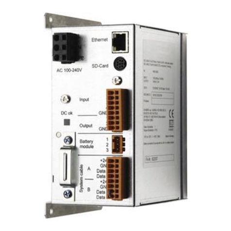
ECC function controller
with Ethernet connection
(60 W) . . . . . . . . . . . . . . . . . . . 4893 00 00
System cable for continuous operation in water,
halogen free 100 m . . . . . . . . . 84-032-12.468
halogen free 25 m . . . . . . . . . . 84-032-12.534
System line,
not halogen-free, 100 m . . . . . 84-032-12.563
not halogen-free, 25 m . . . . . . 84-032-12.720

11
18-05.984b-FR.fm
0Français
AQUAPAY - Contacteur à pièces pour 2 - 31 douches, 24 V DC
7612982130793 ......... jetons
7612982130809 ......... EURO 0,50
Les graphiques sont disponibles dans la notice de montage et de mise en service
allemande.
0Table des matières
1. Abréviations et unités . . . . . . . . . . . . . . . . . . . . . . . . . . . . . . . . . . 12
2. Explication des symboles . . . . . . . . . . . . . . . . . . . . . . . . . . . . . . . 12
3. Garantie . . . . . . . . . . . . . . . . . . . . . . . . . . . . . . . . . . . . . . . . . . . . 12
4. Remarques importantes . . . . . . . . . . . . . . . . . . . . . . . . . . . . . . . . 13
Description du produit
5. Application . . . . . . . . . . . . . . . . . . . . . . . . . . . . . . . . . . . . . . . . . . 13
6. Données techniques. . . . . . . . . . . . . . . . . . . . . . . . . . . . . . . . . . . 13
7. Contenu de la livraison. . . . . . . . . . . . . . . . . . . . . . . . . . . . . . . . . 13
8. Dimensions. . . . . . . . . . . . . . . . . . . . . . . . . . . . . . . . . . . . . . . . . . 13
9. Exemple d’installation. . . . . . . . . . . . . . . . . . . . . . . . . . . . . . . . . . 14
Montage, fonctionnement et mise en service
10. Préparation du raccordement électrique à effectuer par le client . 14
11. Montage . . . . . . . . . . . . . . . . . . . . . . . . . . . . . . . . . . . . . . . . . . . . 14
12. Mise en service. . . . . . . . . . . . . . . . . . . . . . . . . . . . . . . . . . . . . . . 16
13. Fonctionnement . . . . . . . . . . . . . . . . . . . . . . . . . . . . . . . . . . . . . . 17
14. Réglages . . . . . . . . . . . . . . . . . . . . . . . . . . . . . . . . . . . . . . . . . . . 17
Entretien
15. Maintenance et entretien . . . . . . . . . . . . . . . . . . . . . . . . . . . . . . . 18
16. Élimination de pannes . . . . . . . . . . . . . . . . . . . . . . . . . . . . . . . . . 18
17. Pièces de rechange . . . . . . . . . . . . . . . . . . . . . . . . . . . . . . . . . . . 18

12
18-05.984b-FR.fm
1. Abréviations et unités
2. Explication des symboles
Avertissement !
Le non-respect des consignes est susceptible d'induire un danger de mort ou de
provoquer des blessures corporelles.
Attention !
Le non-respect des consignes est susceptible de provoquer des dommages
matériels.
☞Important !
Le non-respect des consignes est susceptible de provoquer des
dysfonctionnements du produit.
☞Informations utiles pour une utilisation optimale du produit.
3. Garantie
La responsabilité est assumée conformément aux conditions générales de vente et
de livraison.
Utiliser uniquement des pièces de rechange d’origine !
SELV Safety Extra Low Voltage, basse tension de
protection
RCD Residual Current Protective Device,
Interrupteur de protection contre les courants de
court-circuit
EA-Nr. Numéro d’article européen
FAR-Best.-Nr. Numéro de commande Franke Aquarotter
Conversion 1 mm = 0,03937 pouce
1 pouce = 25,4 mm
Dans les graphiques, les longueurs sont indiquées en mm.

13
18-05.984b-FR.fm
4. Remarques importantes
• Seul un spécialiste est habilité à effectuer le montage, la mise en service et
l’entretien de l’installation, ces opérations étant effectuées selon les instructions
fournies, conformément aux prescriptions légales et aux règles techniques
reconnues.
• Il convient de respecter les conditions techniques de raccordement des
entreprises locales de distribution d’eau et d’énergie.
• Ne faire fonctionner le contacteur à pièces qu'avec une basse tension de
protection avec séparation sûre (SELV).
• Sous réserve de modifications.
5. Application
Contacteur de pièces AQUAPAY pour la distribution payante d'eau pour la
commande de 2 à 31 robinetteries de douches A3000 open. Écran pour le guide-
opérateur et l'affichage de douches libres, sélection via le bouton-poussoir. La durée
d'écoulement par pièce en étapes de secondes est réglable jusqu'à 8 min. et est
préréglée sur 3 min. Interruption automatique de la durée d'écoulement en cas de
non-prélèvement d'eau.
6. Données techniques
7. Contenu de la livraison
8. Dimensions
Dimensions du boîtier : 240 x 220 x 130 mm (L x H x P)
Tension de raccordement : 24 V DC
Puissance absorbée : 10 W
Type de protection : IP 22
Pièce Désignation
1 Contacteur à pièces
3Vis
3 Cheville
1 Notice de montage et de mise en service

14
18-05.984b-FR.fm
9. Exemple d’installation
A : max. 31 robinets
1 PC avec logiciel système
2 Contrôleur de fonctionnement ECC
3 Câblessystème
4 Contacteur à pièces
5 Robinetterie
6 Résistance de terminaison
10. Préparation du raccordement électrique à effectuer par le client
Avertissement !
• L’alimentation en tension (non comprise dans le contenu de la livraison) doit être
placée en dehors de la zone humide, dans un local séparé.
• Ne faire fonctionner le contacteur à pièces qu'avec une basse tension de
protection avec séparation sûre (SELV) 24 V DC.
• Protéger le raccordement électrique avec un interrupteur de protection contre les
courants de court-circuit (RCD) pour un courant de court-circuit nominal maximal
de 30 mA.
Le non-respect des consignes est susceptible d'induire un danger de mort ou de
provoquer des dommages matériels, par exemple par électrocution ou par incendie.
☞Poser le câble système (à fournir par le client) dans le tube vide (non compris dans
la livraison) et réaliser une boucle entre l’alimentation en tension et la robinetterie et
le contacteur à pièces.
11. Montage
Montage du distributeur T électrique
☞Important !
Les composants du distributeur T électrique doivent uniquement être installés hors
tension.
☞Câbles système recommandés voir chapitre 17., accessoires.
En cas d’utilisation d’autres câbles comme câbles système, tenir compte du code
couleur modifié. Le diamètre extérieur ne doit pas être supérieur à 7,5 mm.
11.1
Retirer la gaine (a) du câble système (sur env. 40 mm).
11.2
Enficher l’écrou-raccord (c) sur le câble système (b) jusqu’à la butée.
☞Les fentes de guidage des brins sont désignées par les chiffres 1 à 4.

15
18-05.984b-FR.fm
11.3
Enfiler les brins (d) en fonction de leur couleur dans les fentes de guidage (e).
11.4
Couper à ras les extrémités des brins qui dépassent, c'est-à-dire de façon à ce qu'ils
ne dépassent pas.
11.5
Placer l’écrou-raccord (c) sur le distributeur T électrique (f) et serrer au couple
prescrit (1,2 Nm).
Attention !
Tenir compte de la polarité.
Une couleur de brin doit être présente dans un même guide au niveau des deux
écrous-raccords.
☞Lors du vissage des écrous-raccords, le contact électrique et la décharge de traction
sont effectués automatiquement.
Des joints spéciaux protègent contre la poussière et l’eau.
Le contacteur à pièces convient uniquement pour le montage apparent.
☞Important !
Aligner le contacteur à pièces horizontalement.
Le non respect entraîne des dysfonctionnements du contacteur à pièces.
11.6
Dévisser le cadre du contacteur à pièces (PIN-Torx TX-15).
11.7
Visser le distributeur T électrique.
11.8
Monter le cadre horizontalement au niveau du mur.
11.9
Introduire le câble système dans le contacteur à pièces par le cadre.
11.10
Accrocher le contacteur à pièces en haut au niveau de l'attache et le mettre en
place.
11.11
Fixer le bas du contacteur à pièces à l'aide de vis.
11.12
Raccorder la conduite entre le contacteur à pièces et le distributeur T électrique.
11.13
Installer la coupe pour les pièces.
11.14
Fermer la porte du contacteur à pièces.
11.15
Le contacteur à pièces est maintenant opérationnel.
AB
1 marron rouge
2 blanc blanc
3 bleu bleu
4 noir noir
A : Ecrou-raccord
B : N° de comm. FAR-- 84-032-12.468
N° de comm. FAR-- 84-032-12.534
N° de comm. FAR-- 84-032-12.563
N° de comm. FAR-- 84-032-12.720

16
18-05.984b-FR.fm
12. Mise en service
Pour garantir le fonctionnement correct, un numéro doit être attribué à chaque
douche.
12.1
Activer l'alimentation en tension.
12.2
Attendre au moins 4 minutes. Ce n'est qu'à ce moment que fonctionne la
commutation du set et du mode de fonctionnement.
☞Toutes les robinetteries Aquapay doivent être dans l'état de fonctionnement
« Set B ».
☞Toutes les robinetteries Aquapay doivent être réglées sur le mode Master AQUAPAY
(réglage, voir mode d'emploi 18-05.648, chapitre fonctions spéciales).
12.3
Dans le logiciel système ou sur le contrôleur de fonctionnement ECC, régler toutes
les robinetteries Aquapay sur l'état de fonctionnement « Set B ».
12.4
Désactiver l'alimentation en tension.
12.5
Sur le module Aquapay (a), enficher le cavalier (b) sur les deux broches
supérieures.
12.6
Activer l'alimentation en tension.
☞En fonction du nombre de robinetteries Aquapay, quelques minutes peuvent
s'écouler avant que l'affichage « do NOT PAY » s'éteigne.
• Le nombre de robinetteries Aquapay détectées par le contacteur à pièces
s'affiche à l'écran.
12.7
Si le nombre affiché correspond au nombre présent, enficher le cavalier (b) sur les
deux broches inférieures.
• Le module Aquapay envoie aux robinetteries Aquapay la commande d'adressage
des détecteurs et passe en mode d'identification.
12.8
Si l'écran affiche « 1 », déclencher la douche devant être affectée à l'emplacement
de douche 1.
12.9
Si l'écran affiche « 2 », déclencher la douche devant être affectée à l'emplacement
de douche 2.
12.10
Répéter cette procédure jusqu'à ce qu'un emplacement soit affecté à chaque
douche.
• Lorsque toutes les robinetteries Aquapay sont adressées, la configuration est
enregistrée dans le module Aquapay.
• L'écran affiche « XXX ».
• Après l'enregistrement, le contacteur à pièces fonctionne en mode normal.

17
18-05.984b-FR.fm
13. Fonctionnement
13.1
Le prochain emplacement de douche libre s'affiche à l'écran (a).
• Affichage : Pay X
13.2
Si l'emplacement de douche libre affiché n'est pas souhaité, il est possible d'en
choisir un autre à l'aide du bouton-poussoir (b).
13.3
Insérer les pièces dans le vérificateur (c).
• La durée d'écoulement s'affiche.
13.4
10 s après la dernière insertion de pièce, « GO X » s'affiche à l'écran.
• Le compte temps est transféré à la douche.
• La douche est débloquée.
Possibilité de commutation vers le mode de distribution d'eau non payante
13.5
Commuter l'interrupteur (e) du module Aquapay (d) vers le haut.
• La mention « do NOT PAY » s'affiche à l'écran.
14. Réglages
Différents réglages peuvent être réalisés avec le logiciel gratuit (N° de comm.
FAR 4897 00 00).
☞La douche reste verrouillée pendant 2 min après chaque douche. Cette durée
d'occupation ne peut pas être modifiée.
Paramètres réglables
• Durée de paiement :
– Durée pendant laquelle les pièces ou les jetons doivent être insérés dans le
mécanisme de paiement. La douche est déverrouillée au terme de cette durée.
Il n'est plus possible de rajouter des pièces.
– Plage réglable : 1-30 sec
– Réglage d’usine : 10 sec
• Unité de distribution :
– Durée de distribution par unité payée. Il est possible d'insérer jusqu'à 30
pièces.
– Plage réglable : 1-510 sec
– Réglage d’usine : 3 min
• Durée d'expiration :
– Durée qui s'écoule avant l'expiration de l'avoir en cas de non utilisation. La
douche est déverrouillée pour le paiement.
– Plage réglable : 1-30 min
– Réglage d’usine : 5 min

18
18-05.984b-FR.fm
15. Maintenance et entretien
• Le contacteur à pièces ne nécessite aucun entretien particulier.
• En cas d'encrassement extérieur, essuyer le boîtier avec un chiffon en microfibres
humide.
16. Élimination de pannes
S'il n’est pas possible d’éliminer la panne ou si celle-ci n’apparaît pas dans le
tableau d’élimination des pannes, nous vous prions de bien vouloir prendre contact
avec le service après-vente !
17. Pièces de rechange
Défaut Cause Élimination
L’eau ne coule pas – Alimentation en tension
interrompue
➯Rétablir
– Contacteur à pièces défectueux ➯Remplacer
L’eau coule en
permanence
– Contacteur à pièces défectueux ➯Remplacer
0
Désignation N° de comm.
1 Système d'insertion des pièces
pour jetons . . . . . . . . . . . . . . . . 84-032-12.871
pour 0,50 €. . . . . . . . . . . . . . . . 84-032-12.858
2 Coupe pour pièces . . . . . . . . . . . . 84-032-02.144
Accessoire N° de comm.
Contrôleur de fonctionnement ECC
avec connexion Ethernet
(60 W) . . . . . . . . . . . . . . . . . . . 4893 00 00
Câbles système pour une utilisation continue dans
l’eau,
sans halogènes 100 m . . . . . . 84-032-12.468
sans halogènes 25 m . . . . . . . 84-032-12.534
Câbles système,
avec halogènes 100 m . . . . . . 84-032-12.563
avec halogènes 25 m . . . . . . . 84-032-12.720

19
18-05.984b-IT.fm
0Italiano
AQUAPAY - Gettoniera con temporizzatore incorporato a monete/gettoni per
2 - 31 postazioni doccia, 24 V DC
7612982130793 ......... gettoni
7612982130809 ......... monete da 0,50 EURO
Per le grafiche fare riferimento alle istruzioni per il montaggio e l’uso in tedesco.
0Sommario
1. Abbreviazioni e unità . . . . . . . . . . . . . . . . . . . . . . . . . . . . . . . . . . 20
2. Spiegazione dei simboli . . . . . . . . . . . . . . . . . . . . . . . . . . . . . . . . 20
3. Garanzia. . . . . . . . . . . . . . . . . . . . . . . . . . . . . . . . . . . . . . . . . . . . 20
4. Avvertenze importanti. . . . . . . . . . . . . . . . . . . . . . . . . . . . . . . . . . 20
Descrizione del prodotto
5. Uso . . . . . . . . . . . . . . . . . . . . . . . . . . . . . . . . . . . . . . . . . . . . . . . . 21
6. Specifiche tecniche. . . . . . . . . . . . . . . . . . . . . . . . . . . . . . . . . . . . 21
7. Stato di fornitura . . . . . . . . . . . . . . . . . . . . . . . . . . . . . . . . . . . . . . 21
8. Dimensioni . . . . . . . . . . . . . . . . . . . . . . . . . . . . . . . . . . . . . . . . . . 21
9. Esempio di installazione . . . . . . . . . . . . . . . . . . . . . . . . . . . . . . . . 21
Montaggio, funzionamento e messa in esercizio
10. Preparazione sul posto dell’allacciamento elettrico . . . . . . . . . . . 22
11. Montaggio. . . . . . . . . . . . . . . . . . . . . . . . . . . . . . . . . . . . . . . . . . . 22
12. Messa in esercizio . . . . . . . . . . . . . . . . . . . . . . . . . . . . . . . . . . . . 23
13. Funzionamento. . . . . . . . . . . . . . . . . . . . . . . . . . . . . . . . . . . . . . . 24
14. Impostazioni . . . . . . . . . . . . . . . . . . . . . . . . . . . . . . . . . . . . . . . . . 25
Manutenzione
15. Manutenzione e cura . . . . . . . . . . . . . . . . . . . . . . . . . . . . . . . . . . 25
16. Eliminazione dei guasti. . . . . . . . . . . . . . . . . . . . . . . . . . . . . . . . . 25
17. Pezzi di ricambio . . . . . . . . . . . . . . . . . . . . . . . . . . . . . . . . . . . . . 26

20
18-05.984b-IT.fm
1. Abbreviazioni e unità
2. Spiegazione dei simboli
Avvertenza!
La mancata osservanza può causare pericolo per la vita o lesioni corporee.
Attenzione!
La mancata osservanza può causare danni materiali.
☞Importante!
La mancata osservanza può causare malfunzionamenti del prodotto.
☞Informazioni utili per l’uso ottimale del prodotto.
3. Garanzia
La garanzia viene accordata conformemente alle nostre condizioni generali di
vendita e consegna.
Utilizzare esclusivamente pezzi di ricambio originali!
4. Avvertenze importanti
• Montaggio, messa in esercizio e manutenzione solo da parte di un tecnico
specializzato secondo le presenti istruzioni, nel rispetto delle prescrizioni di legge
e delle regole riconosciute della tecnica.
• Rispettare le condizioni tecniche di allacciamento delle società locali di
erogazione di energia elettrica e di approvvigionamento idrico.
• Utilizzare la gettoniera solo a bassissima tensione di protezione con separazione
sicura (SELV).
• Sotto riserva di modifiche tecniche.
SELV Safety Extra Low Voltage, bassissima tensione di
sicurezza
RCD Residual Current Protective Device,
interruttore di sicurezza per correnti di guasto
EA-Nr. Codice articolo europeo
FAR-Best.-Nr. Numero d'ordine Franke-Aquarotter
Fattore di conversione 1 mm = 0,03937 pollici
1 pollice = 25,4 mm
Tutte le quote nelle grafiche sono espresse in millimetri.
Other manuals for AQUA802
1
This manual suits for next models
3
Table of contents
Languages:
Other Franke Controllers manuals

Franke
Franke ZAQUA005 User manual

Franke
Franke Protronic A3000 open User manual

Franke
Franke ZA3OP0024 User manual

Franke
Franke ECC2 Function Controller User manual

Franke
Franke AQUA3000OPEN ZA3OP0023 User manual

Franke
Franke GMKPc JKL Series User manual

Franke
Franke AQUA802 User manual

Franke
Franke ZA3OP0034 User manual