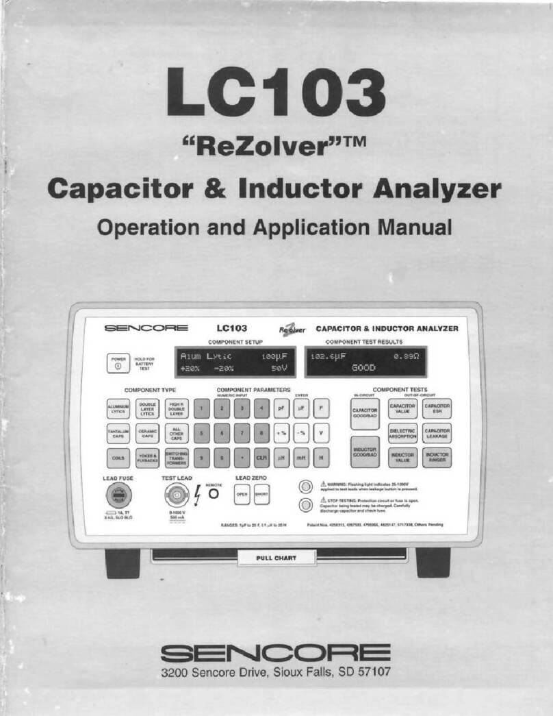
Sencore ReZolver LC103 User guide

1
LC103
“ReZolver”™
Capacitor & Inductor Analyzer
Operation and Application Manual
3200 Sencore Drive, Sioux Falls, SD 57107
!
!
LC103
COMPONENT SETUP
COMPONENTTYPE
LEAD FUSE TEST LEAD LEAD ZERO
NUMERIC INPUT ENTER IN-CIRCUIT OUT-OF-CIRCUIT
COMPONENT PARAMETERS COMPONENTTESTS
COMPONENTTEST RESULTS
CAPACITOR & INDUCTOR ANALYZER
POWER HOLD FOR
BATTERY
TEST
ALUMINUM
LYTICS
DOUBLE
LAYER
LYTICS
HIGH R
DOUBLE
LAYER
1 2 3 4 pF µF F
CAPACITOR
GOOD/BAD
INDUCTOR
GOOD/BAD
CAPACITOR
VALUE CAPACITOR
ESR
CAPACITOR
LEAKAGE
INDUCTOR
RINGER
DIELECTRIC
ABSORPTION
INDUCTOR
VALUE
+ % - % V
µH mH H
5678
90•CLR
ALL
OTHER
CAPS
SWITCHING
TRANS-
FORMERS
TANTALUM
CAPS CERAMIC
CAPS
YOKES &
FLYBACKS
COILS
1A,TT
2 AG,SLO BLO 0-1000V
500 mA
REMOTE
OPEN
RANGES: 1pF to 20 F, 0.1 µH to 20 H Patent Nos. 4258315,4267503, 4795966, 4825147, 5717338, Others Pending
WARNING: Flashing light indicates 25-1000V
applied to test leads when leakage button is pressed.
STOPTESTING: Protection circuit or fuse is open.
Capacitor being tested may be charged. Carefully
discharge capacitor and check fuse.
SHORT
F
U
S
E
F
U
S
E
A
lum
L
ytic
100
μ
F
+20% -20% 50
V
102.6
μ
F
0.89
Ω
GooD
PULL CHART

2
WARNING
PLEASE OBSERVE THESE SAFETY PRECAUTIONS
There is always a danger present when using electronic test equipment.
Unexpected high voltages can be present at unusual locations in defective
equipment. Every precaution has been taken in the design of your instrument to
insure that it is as safe as possible. However, safe operation depends on you, the
operator. Become familiar with the equipment you are working with, and observe
the following safety precautions.
1. Never exceed the limits of this instrument as given in the specifications section or other special
warnings provided in this manual.
2. A severe shock hazard can result if the chassis of the equipment being serviced is tied to the “hot”
side of the AC line. An isolation transformer should always be used with hot-chassis equipment. Also,
be sure that the top of your workbench and the floor underneath it are dry and made of non-conductive
materials.
3. Remove the circuit power before making connections to high voltage points. If this cannot be done,
be sure to avoid contact with other equipment or metal objects. Place one hand in your pocket and
stand on an insulated floor to reduce the possibility of shock.
4. Discharge filter capacitors (after removing power) before connecting to any part of the circuit
requiring power to be removed.
5. Be sure your equipment is in good order. Broken or frayed test leads can be extremely dangerous
and can expose you to dangerous voltages.
6. Remove test leads immediately after the test has been completed to reduce the possibility of shock.
7. Do not work alone when working on hazardous circuits. Always have another person close by in
case of an accident. Remember, even a minor shock can be the cause of a more serious accident, such
as falling against the equipment, or coming in contact with high voltages.
8. Improper Fuse(s) Void Warranty. Fuses are for your protection, so always replace fuse with proper
type and current rating. The proper fuse type description is marked near the fuse holder and in the
manual. Always:
A. Be sure you are replacing the right fuse. On units with more than one fuse, be sure you are
placing the proper fuse value in the fuse holder.
B. Have the proper size replacement fuse in stock. With each new instrument, be sure to update
your fuse inventory with any special value fuses your instrument may require.
9. Explanation of symbols.
This marking indicates that the operator must refer to an explanation in the operating instructions.
A terminal at which a voltage with respect to another terminal or part exists or may be adjusted to 1,000
volts or more.

1
LC103
“ReZolver”™
Capacitor & Inductor Analyzer
Operation and Application Manual
3200 Sencore Drive, Sioux Falls, SD 57107

2
TABLE OF CONTENTS
SAFETY PRECAUTIONS ........ Inside Front Cover
DESCRIPTION
Introduction............................................................4
Features..................................................................4
Specifications ......................................................... 5
Front Panel Controls...............................................7
Rear Panel Controls................................................8
Supplied Accessories ..............................................8
Optional Accessories...............................................9
OPERATION
Introduction.......................................................... 10
AC Power Operation............................................. 10
Battery Operation.................................................. 11
Battery Test ....................................................... 12
Recharging the Battery....................................... 12
Auto-Off............................................................ 12
STOP TESTING Indication................................ 13
Test Lead Fuse................................................... 13
Test Leads........................................................... 13
Adjustable In-Circuit Test Probe......................... 13
Test Lead Mounting Clip.................................... 14
Lead and Probe Zeroing..................................... 14
Entering Component Data.................................. 15
Component Type................................................ 15
Component Value .............................................. 15
Tolerance........................................................... 15
Leakage Voltage ................................................ 16
In-Circuit Capacitor Testing.............................. 17
Value and ESR Testing ...................................... 17
Automatic EIA GOOD/BAD Testing.................. 17
SUGGEST REMOVAL Indication..................... 17
Out-of-Circuit Capacitor Testing....................... 18
Out-of-Circuit Capacitor Parameter Testing..... 18
Component Test Results..................................... 18
Measuring Capacitor Value................................ 18
Measuring Capacitor ESR .................................. 18
Measuring Capacitor D/A................................... 19
Measuring Capacitor Leakage ............................ 20
Leakage in Paper, Mica and Film Capacitors ...... 21
Leakage in Ceramic Capacitors .......................... 21
Leakage in Aluminum Electrolytics.................... 21
Leakage in Tantalum Electrolytics...................... 21
Leakage in Non-Polarized (bipolar) Electrolytics 21
Leakage Charts .................................................. 22
Automatic GOOD/BAD Capacitor Testing........ 24
In-Circuit Inductor Testing................................ 25
Out-of-Circuit Inductor Testing......................... 25
Measuring Inductor Value.................................. 25
Automatic GOOD/BAD Inductor Value Testing. 26
Inductor Ringer Test........................................... 26
Error Messages................................................... 27
RS-232 OPERATION.........................................28
Connecting to the Computer............................... 28
Sending Data to the LC103.................................28
Component Type Commands..............................29
Value Multipliers...............................................29
Setting the Leakage Voltage...............................30
Test Function Commands...................................30
General Codes....................................................30
Receiving Data from the LC103.......................... 31
Data Format.......................................................31
Error Testing...................................................... 32
Shorted Capacitors.............................................32
Open Inductors...................................................32
Making Leakage Tests........................................32
Making ESR Tests..............................................33
APPLICATIONS
Introduction ........................................................34
Identifying Capacitor Types............................... 34
Aluminum Electrolytics......................................35
Tantalum Electrolytics........................................35
Double Layer and “High R” Electrolytics ...........36
Ceramic Capacitors............................................36
Other Capacitor Types........................................ 36
Identifying Inductor Types.................................37
Yokes and Flybacks ...........................................37
Switching Transformers ..................................... 37
Coils.................................................................. 37
Identifying Unknown Components.....................38
Capacitor Testing................................................ 38
Capacitance Measurement Accuracy...................38
Measuring Small Capacitance Values
in Noisy Environments ....................................38
Interpreting Capacitor Value Readings................39
In-Circuit Capacitor Test....................................39
Testing Non-Polarized (Bi-Polar) Electrolytics ...40
Checking Leakage in a Multi-Section Electrolytic40
Dielectric Stress.................................................40
Intermittent Capacitors.......................................40
Checking Ceramic Capacitor
Temperature Characteristics.............................40
Inductor Testing..................................................41
In-Circuit Inductor Test......................................41
Mutual Inductance..............................................41
Ringing Peaking Coils........................................ 41
Ringing Metal Shielded Coils.............................41
Testing Flyback Transformers
and Deflection Yokes..................................... 41
Ringing Flyback Transformers.........................41
Leakage Testing Flyback Transformers............42


3
Ringing Deflection Yokes................................ 43
Transmission Cable Testing................................ 43
Testing Coaxial Cable........................................ 43
Determining a Cable’s Length or
Distance to an Open......................................... 44
Locating a Short in Coaxial Cable ...................... 44
Determining Capacitance and Inductance
Per Foot .......................................................... 45
Identifying Aging Cable..................................... 45
Testing High Voltage Diodes............................... 46
High Potential Testing ........................................ 46
Measuring High Voltage Resistors
to 1 Gigaohm ................................................. 47
APPENDIX
Introduction........................................................ 48
Capacitor Theory................................................ 48
Capacitor Types.................................................. 49
Aluminum Electrolytics...................................... 49
Tantalum Electrolytics ....................................... 49
Ceramics............................................................ 49
Capacitor Failure Modes.................................... 51
Value Change..................................................... 51
ESR................................................................... 51
D/A.................................................................... 52
Leakage ............................................................. 52
GLOSSARY........................................................ 57
WARRANTY AND SERVICE...Inside Back Cover

4
DESCRIPTION
INTRODUCTION
Capacitors and inductors are widely used in electronic
systems. Capacitor and inductor usage continues to
increase since neither of these components can be
physically incorporated into ICs on a broad basis.
Though capacitors and inductors have changed in
physical size, they still perform the same basic functions.
In today's high tech electronic circuits, capacitors and
inductors are critical to normal circuit operation.
In today's high performance circuits, value, leakage,
dielectric absorption, and ESR are important indicators
of a capacitor's ability to perform properly in-circuit.
Inductors too, must be of proper value and quality.
Unless all of these parameters are thoroughly analyzed,
problem capacitors and inductors may be missed and
troubleshooting becomes a guessing game.
The Sencore LC103 ReZolver takes the guesswork out
of capacitor and inductor testing. It provides in-circuit
capacitor value and ESR tests along with automatic out-
of-circuit tests for capacitor value, leakage, ESR, and
dielectric absorption. Inductors are automatically
analyzed in-circuit for value or out-of-circuit for value
and quality with patented tests.
The LC103 is a complete, automatic, microprocessor-
controlled capacitor and inductor analyzer. Its features
make it ideally suited for both single component
analyzing in service or maintenance work, or for large
volume, batch testing in a lab or incoming inspection.
FEATURES
The Sencore LC103 ReZolver is a dynamic, portable,
automatic, in- or out-of-circuit capacitor and inductor
analyzer. It is designed to quickly identify defective
capacitors and inductors by providing fast in-circuit tests
and complete analyzing out-of-circuit. The test results
are displayed on an easy-to-read fluorescent display in
common terms. All capacitor and inductor test results
may also be displayed as GOOD/BAD compared to
standards adopted by the Electronic Industries
Association (EIA).
In addition to testing capacitors for value up to 20
Farads, the LC103 checks capacitors for leakage at their
rated working voltage, up to 1000 Volts. ESR is
checked with a patented test, and an automatic, patented
test checks for excessive dielectric absorption. A
patented inductance value test provides a fast, accurate
test of true inductance. A patented ringing test checks
coils, deflection yokes, switching power supply
transformers, and other non-iron core inductors with a
fast, reliable GOOD/BAD quality test.
Automatic lead zeroing balances out test lead
capacitance, resistance, and inductance for accurate test
results. The LC103 is protected from external voltages
applied to the test leads by a fuse located on the front
panel. Stop-testing circuitry locks out all test buttons
when voltage is sensed on the test leads.
Battery operation makes the LC103 completely portable
for on-location troubleshooting in all types of servicing
including industrial equipment, avionics, and cable fault
locating. An optional SCR260 SCR & TRIAC TEST
ACCESSORY extends the LC103 test capabilities to
provide a fast, accurate test of these components. The
LC103 may be used with an RS-232 computer interface
for fully automatic, computer controlled testing in a
laboratory or incoming inspection area.

5
SPECIFICATIONS
IN-CIRCUIT TESTS (Capacitors and Inductors)
Dynamic in-circuit tests to determine whether the
capacitor or inductor is good or bad.
COMPONENT TYPES: Electrolytic, double layer lytic,
tantalum, ceramic, and other capacitors. Yokes,
flybacks, switching transformers, and coils.
RANGE: INDUCTORS – 3.18 uH to 3.18 H
CAPACITORS:
Value: 0.002 uF to 20,000 uF
ESR: 0.02uF to 20,000uF
ACCURACY: Same as Out-of-Circuit tests for known
good inductors and capacitors with no parallel
components.
CAPACITORS (Out-of-circuit)
VALUE
Dynamic test of capacity value is determined by
applying a constant current to the capacitor and
measuring the dV/dt:
10 uA 1.0 pF to 0.2 uF
100 uA 0.2uF to 2 uF
60 mA 2.0 uF to 2,000 uF
416 mA 2,000 uF to 20,000 uF
capacitors from 20,000 uF to 20 F are pulsed with
100 mA
ACCURACY: +/- 1%; +/- l pF; +/- 1 digit for values to
1990 uF; +/- 5%; +/- 0.1% of range, full scale for
values 2000 uF to 19.99 F.
RESOLUTION AND RANGES: 1.0 pF to 19.99 F, fully
autoranged
0.1 pF 1.0 pF to 199.9 pF
1.0 pF 200 pF to 1999 pF
0.00001 uF 0.002 uF to 0.01999uF
0.0001 uF 0.02 uF to 0.1999 uF
0.001 uF 0.2 uF to 1.999 uF
0.01 uF 2.0uF to 19.99 uF
0.1 uF 20.0 uF to 199.9 uF
1.0 uF 200 uF to 1,999 uF
10 uF 2,000 uF to 19,990 uF
100 uF 20,000 uF to 199,900 uF
0.001 F 0.2 F to 1.999 F
0.01 F 2.0 F to 19.99 F
LEAKAGE
ACCURACY: +/- 5%; +/- 1 digit
APPLIED VOLTAGE: Keyboard entry; 1.0 to 1000
volts in 0.1 volt steps; accuracy +0% -5%. Short
circuit current limited to 900 mA, power limited to 9
Watts.
RESOLUTION AND RANGES: 0.0l uA to 20 mA, fully
autoranged
0.01 uA 0.01 uA to 19.99 uA
0.l uA 20.0 uA to 199.9 uA
1.0 uA 200 uA to 1999 uA
0.01 mA 2.00 mA to 19.99 mA
EQUIVALENT SERIES RESISTANCE (ESR)
(U.S Patent #4,795,966)
ACCURACY: +/-5%; +/-l digit
CAPACITOR RANGE: 0.01 uF to 19.99 F
RESOLUTION AND RANGES: 0.1 ohm to 1999 ohms,
fully autoranged for capacitor values greater than or
equal to 1 uF
0.01 ohm 0.1 ohm to 1.99 ohms
0.1ohm 2.0 ohms to 19.9 ohms
1 ohm 20 ohms to 1999 ohms
for capacitor values less than 1 uF
1ohm 1ohm to 1999 ohms
DIELECTRIC ABSORPTION
(U.S. Patent #4,267,503)
ACCURACY: +/- 5% of reading +/- 1 count
RANGE: 1 to 100%
CAPACITOR RANGE: 0.01 uF to 19.99 F
INDUCTORS (Out-of-Circuit)
VALUE (U.S. Patent #4,258,315)
A dynamic test of value determined by measuring the
EMF produced when a changing current is applied to
the coil under test.
CURRENT RATES: automatically selected
19.5 mA/uSec 0.1 uH to 18 uH
1.95 mA/uSec 18 uH to 180 uH
0.195 mA/uSec 180 uH to 1.8 mH
19.5 mA/mSec 1.8 mH to 18 mH
1.95 mA/mSec 18 mH to 180 mH
0.195 mA/mSec 180 mH to 1.8 H
17.5 mA/Sec 1.8 H to 19.99 H
ACCURACY: +/-2%; +/-1 digit +/-0.1 uH
RESOLUTION AND RANGES: 0.10 uH to 20 H, fully
autoranged
0.01 uH 0.l uH to 19.99 uH
0.1uH 20.0 uH to 199.9 uH
1.0 uH 200 uH to 999 uH
0.001 mH 1.000 mH to 1.999 mH
0.01 mH 2.00 mH to 19.99 mH
0.l mH 20.0 mH to 199.9 mH
1 mH 200 mH to 999 mH
0.001 H 1.000 H to 1.999 H
0.01 H 2.00 H to 19.99 H
RINGING TEST (U.S. Patent #3,990,002)
A dynamic test of inductor quality determined by
applying an exciting pulse to the inductor and
counting the number of cycles the inductor rings
before reaching a preset damping point.
INDUCTOR RANGE: 10 uH and larger, non-iron core
ACCURACY: +/- 1 count on readings between 8 and 13
Rings
RESOLUTION: +/- 1 count
EXCITING PULSE: 5 volts peak

6
SPECIFICATIONS CONTINUED
DISPLAY
COMPONENT TEST RESULTS
TYPE: 2 x 17 Alphanumeric Vacuum Fluorescent
READINGS: Fully autoranged with auto decimal
placement. One or two place holding zeros added as
needed to provide standard value readouts of pF, uF,
uH, or mH.
COMPONENT SETUP
TYPE: 2 x 20 Alphanumeric Vacuum Fluorescent
READINGS: All component types, component value,
tolerance, and voltage rating.
GENERAL
TEMPERATURE: operating range: 32oto 104oF (0oto
40oC) range for specified accuracy (after 10 minute
warm-up): 50oto 86oF (10oto 30oC)
HUMIDITY: 0-90%, no condensation
MAXIMUM ALTITUDE: 4,000 meters
POWER: 105-130V AC, 60Hz, 30 watts with supplied
PA251 power adapter. Battery operation with
optional BY289 rechargeable battery. 210-230V AC
operation with optional PA252 Power Adapter.
AUTO-OFF: Removes power during battery operation if
unit sits idle longer than 5 minutes.
BATTERY LIFE: 2 hours for typical operation.
SIZE: 6" x 9" x 11.5" (15.2 cm x 22.9 cm x 29.l cm) HWD
WEIGHT: 6.0 lbs. (2.7 kg) without battery, 7.6 lbs.
(3.4 kg) with battery
GOOD/BAD INDICATION: Functions on all tests.
Requires user input of component type and value, or
input of desired limits.
Specifications subject to change without notice

7
Fig. 1: Location of front panel controls.
FRONT PANEL CONTROLS
1. POWER Button – Press to power unit on or off. Press
and hold for Battery Test.
2. COMPONENT TYPE Buttons – Use to select
component type to be tested.
a-f: Press to select desired capacitor type
g-i: Press to select desired inductor type
3. LEAD FUSE – Unscrew for access to the test lead fuse.
4. TEST LEAD Jack – BNC type jack to connect test leads
to unit.
5. LEAD ZERO Buttons – Use to balance out test lead
impedance.
a. OPEN – Press to compensate for tet lead capacitance
with test leads open.
b. SHORT – Press to compensate for test lead
inductance and resistance with test leads shorted.
6. PULL CHART – Provides simplified operating
instructions and quick reference tables.
7. COMPONENT PARAMETERS Buttons – Use to enter
component parameters for limit testing.
a-k: Use to enter numerical portion of parameters.
l: CLR: Press once to clear numeric input. Press twice
to clear all component parameters.
m-o: Capacitor Value Multipliers: Use after numeric input
to enter capacitor value.
p-q: Percentage buttons: Use after numeric input to enter
component tolerance.
r: Volts: Use after numeric input to enter voltage for
capacitor leakage test.
s-u: Inductor Value Multipliers: Use after numeric input
to enter inductor value.
8. WARNING LED – Flashes to indicate leakage voltage
has been set to 25 volts or more. Voltage is onlypresent
when CAPACITOR LEAKAGE button is pressed.
9. STOP TESTING LED – Flashes along with an audible
alarm and “FUSE OPEN” message to indicate test lead
fuse is open.
10. IN-CIRCUIT Test Buttons – Press to test capacitors or
inductors in-circuit.
11. OUT-OF-CIRCUIT Test Buttons
a. Capacitor GOOD/BAD – Press to measure
capacitor value and ESR in-circuit.
b. Inductor GOOD/BAD – Press to measure
inductance value in-circuit.
c. Dielectric Absorption – Press to measure percentage
of dielectric absorption.
d. Capacitor Leakage – Press to measure the amount
of leakage after a voltage has been entered with the
COMPONENT PARAMETERS keypad (6).
e. Inductor Value – Press to measure inductance value.
f. Inductor Ringer – Press to activate Ringer test after
selecting inductor type (2g-i).
12. COMPONENT TEST RESULTS Display – Displays
the resultant value of test.
13. COMPONENT SETUP Display – Displays entered
component type, value, tolerance, and voltage rating.
!
!
LC103
COMPONENT SETUP
COMPONENTTYPE
LEAD FUSE TEST LEAD LEAD ZERO
NUMERIC INPUT ENTER IN-CIRCUIT OUT-OF-CIRCUIT
COMPONENT PARAMETERS COMPONENTTESTS
COMPONENTTEST RESULTS
CAPACITOR & INDUCTOR ANALYZER
POWER HOLD FOR
BATTERY
TEST
ALUMINUM
LYTICS
DOUBLE
LAYER
LYTICS
HIGH R
DOUBLE
LAYER
1 2 3 4 pF µF F
CAPACITOR
GOOD/BAD
INDUCTOR
GOOD/BAD
CAPACITOR
VALUE CAPACITOR
ESR
CAPACITOR
LEAKAGE
INDUCTOR
RINGER
DIELECTRIC
ABSORPTION
INDUCTOR
VALUE
+ % - % V
µH mH H
5678
90•CLR
ALL
OTHER
CAPS
SWITCHING
TRANS-
FORMERS
TANTALUM
CAPS CERAMIC
CAPS
YOKES &
FLYBACKS
COILS
1A,TT
2 AG,SLO BLO 0-1000V
500 mA
REMOTE
OPEN
RANGES: 1pF to 20 F, 0.1 µH to 20 H Patent Nos. 4258315, 4267503, 4795966, 4825147, 5717338,Others Pending
WARNING: Flashing light indicates 25-1000V
applied to test leads when leakage button is pressed.
STOP TESTING:Protection circuit or fuse is open.
Capacitor being tested may be charged. Carefully
discharge capacitor and check fuse.
SHORT
F
U
S
E
F
U
S
E
PULL CHART
Alum Lytic 100
μ
F
+20% -20% 50V
102.6
μ
F 0.89Ω
GooD
a
b
c
d
e
f
g
h
i
a b c
d
e f g
h
i j k
l
m
n o
p
q r
s
t u
11312
2
3
45678910
11

8
REAR PANEL FEATURES
Fig. 2: Location of rear panel features.
1. BATTERY COMPARTMENT COVER –
Provides access to the (optional) BY289
rechargeable battery.
2. RS-232 SERIAL CONNECTOR – Allows
connection to a computer for automated operation.
3. POWER ADAPTER Jack – Connects to supplied
PA251 POWER ADAPTER for 110 VAC operation,
or (optional) PA252 for 220 VAC operation.
SUPPLIED ACCESSORIES
1. Out-of-Circuit Test Leads (39G219) –
Special low capacity cable with E-Z Hook®
clips. Connect to TEST LEAD jack.
2. Adjustable In-Circuit Test Probe (AP291)
patent pending – Exclusive in-circuit probe
with width adjustment wheel and test
activation switch. Connect to TEST LEAD
jack.
3. Test Lead Mounting Clip (64G37) – Use to
hold test leads when not in use.
4. Power Adapter/Charger (PA251) – Plugs
into POWER INPUT to power unit from 105-
130 VAC line. Also recharges the (optional)
BY289 battery when installed inside the
LC103.
Fig. 3: Supplied Accessories

9
OPTIONAL ACCESSORIES
1. Test Lead Adapter (39G144) – Use to adapt Out-
of-Circuit Test Leads to large, screw terminal
capacitors.
2. 220 VAC Power Adapter/Charger (PA252) –
Plugs into POWER INPUT to power the unit from
210-230 VAC line. Also recharges the (optional)
BY289 battery when installed inside the LC103.
3. Touch Test Probe (39D85) – Use for Hi-Pot testing
of circuit board traces.
4. Field Calibrator (FC221)) – Use to periodically
check the calibration of the LC103.
5. Rechargeable Battery (BY289) – Lead acid battery
provides portable operation for the LC103.
6. SCR/TRIAC Test Accessory (SCR260) – Use to
test SCRs and TRAICs.
7. Carrying Case (CC254) – Provides protection and
easy carrying for the LC103 and its accessories.
8. Component Holder (CH255) – Use to hold
components for fast tests when doing volume
testing.
9. Chip Component Test Lead (CH256) – Special
shielded test leads for testing small surface mount
(chip) components out-of-circuit.
Fig. 4: Optional Accessories

10
OPERATION
INTRODUCTION
Before you begin to use the LC103 ReZolver, take a few
minutes to read this section and the Applications
sections of this manual to become familiar with the
features and capabilities of your instrument. After you
have familiarized yourself with the general operation of
the LC103, most tests can be performed with the
information on the front panel.
AC POWER OPERATION
For continuous bench operation, the LC103 is powered
from any standard 105-130 V (50-60 Hz) AC line using
the PA251 Power Adapter. When 220 VAC operation is
required, power the LC103 with the optional PA252 220
VAC Power Adapter. Connect the Power Adapter to the
POWER IN jack located on the rear panel of the LC103.
The power adapter serves as a battery charger to
recharge the (optional) BY289 battery when it is
installed in the unit. The BY289 may be left installed in
the LC103 at all times without danger of over charging.
Connecting the Power Adapter bypasses the auto-off
circuitry in the LC103 and allows uninterrupted
operation.
Fig. 5: Connect the PA251 to the 12 VDC input for
AC bench operation and to recharge the optional
battery.
———————— WARNING —————————
Only use a Sencore PA251 or PA252 Power Adapter
for AC operation. Using an AC adapter other than
the PA251 or PA252 may cause damage to the
LC103, may cause the optional battery (if installed)
to improperly charge, or may cause measurement
errors on low value of components.
———————— ATTENTION ————————
Utilisez seulement le PA251 au PA252 de Sencore
comme adaptateur secteur. L’utilisation d’un
adaptateur secteur pour le LC103 différent du PA251
ou du PA252 peut endommager l’appareil, peut
empêcher la batterie (si installée) de se charger
correctement et peut altérer les measures en affichant
des résultants bas.
To operate the LC103 from an AC line:
1. Connect the AC line cord of the power adapter to an
adequate source of AC power.
2. Connect the power adapter to the POWER INPUT
JACK on the back of the LC103, as shown in figure 5.
3. Push the POWER button on the LC103 and release.
The STOP TESTING LED should momentarily blink
to indicate it is operational and the displays will reset
and read “LC103 ReZolver” – “Ready.”
4. The LC103 is now ready for use. If precise
measurements are required, allow the unit to operate
for 20 minutes to reach specified accuracy.
———————— WARNING —————————
The STOP TESTING Indicator LED should
momentarily blink when the POWER button is first
pressed turning the LC103 on. Failure of the light to
flash indicates a problem with the LED or safety
circuits. DO NOT operate the LC103 in this
condition, since it exposes the operator to dangerous
voltages without adequate warning.
———————— ATTENTION ————————
La LED d’indication d’erreur doit clignoter pour
quelques instants lorsque le bouton de marche/arêt
est utilize pour la mise en marched u LC103. Si cette
LED ne clignote pas, cela indique un probleéme avec
la LED ou le circuit de sécurité. NE PAS utiliser le
LC103 dans ces conditions, car l’utilisateur peut être
exposé á des voltages élevés sans le savoir.

11
BATTERY OPERATION
The LC103 is designed to operate as a completely
portable unit with the optional BY289 rechargeable
battery installed. The operation of the LC103 when it is
battery powered is the same as when it is AC powered
except that the display will dim slightly to reduce the
power consumption and increase battery life. The length
of time the LC103 will operate before the battery needs
recharging depends on several factors: 1. the test
functions used; 2. temperature; 3. battery age.
Leakage tests place the heaviest current drain on the
battery -- greater currents result in shorter battery life
between charging. Value tests place the least drain on
the battery. The LC103 provides approximately 2 hours
of typical operation using battery power. These times, of
course, will vary with temperature and battery age.
As the temperature of the battery decreases, its capacity
also decreases. The operating time between recharging
decreases at the rate of approximately 1 hour for every
20oF drop in temperature below 70oF. The BY289
battery is a sealed, lead acid type that requires no
maintenance other than recharging. As a battery ages, it
will require more frequent recharging. If used properly,
the BY289 will provide several years of service before
needing replacement.
You can maximize the lifetime of the BY289 several
ways:
1. Never allow the battery to deeply discharge. The
LC103 has a built-in battery test and low battery shut
off circuitry. Check the remaining charge periodically
and recharge the battery before the low battery circuit
shuts the unit off.
2. Keep the battery fully charged. The BY289 will not
be harmed if it is left installed in the LC103 during
AC operation. Instead, this will keep the battery fresh
and ready for use and will actually lengthen its useful
lifetime.
3. Recharge the battery before using it if it has sat idle
for more than a couple of weeks. Lead acid batteries
may loose some of their charge if they sit idle for a
period of time.
———————— WARNING —————————
Observe these precautions when using lead acid
batteries:
1. Do not dispose of old lead-acid batteries in fire. This
may cause them to burst, spraying acid through the air.
2. Do not short the “+” and “-“ terminals together. This
will burn open internal connections, making the
battery useless.
3. Do not charge 12 volt lead-acid batteries with a voltage
greater than 13.8 VDC. High charging voltage may
damage the battery or cause it to explode.
4. Do not drop the battery. While lead-acid batteries are
well sealed, they may break if dropped or subjected to
a strong mechanical shock. If the battery does break
and the jelled electrolyte leaks out, neutralize the acid
with baking soda and water.
5. Do not charge the battery below 0oC or above +40oC.
(32oto 104oF).
———————— ATTENTION ————————
Pernez ces precautions lorsque vous utilisez des batteriesá
acide de plumb:
1. Ne pas jeter les batteries á acide de plumbs dans le feu.
Cela peut entrainer leur explosion et des jets d’acides.
2. Ne pas court-circuiter le “+” et le “-“. Cela grille
l’intérieur de la batterie et rend la batterie inutilisable.
3. Ne pas charger la batterie 12V avec un voltage
supérieur a 13,8 V. Un voltage trop élevé peut entrainer
l’explosion de la batterie ou peut l’abimer.
4. Ne pas laisser tomber la batterie. Méme si les batteries
á acide de plomb sont hermétiques, elles peuvent se
casser si on les laisse tomber ou on les soumis a un
schock mechanique important. Si la batterie se casse et
le produit se repent, neutralisez l’acide avec de l’eau et
du bicarbonate de soude.
5. Ne pas charger la batterie en-dessous de 0° C ou au-
dessus de +40° C. (32° - 104° F).
Fig. 6: The optional BY289 is installed in the LC103
for portable operation.
To install the optional BY289 Battery:
1. Open the BATTERY COMPARTMENT COVER
located on the rear of the unit by unscrewing the
thumbscrew. Fold the cover down on its hinge.
2. Slide the battery end that does not have the connector
attached into the battery compartment. (The wire
should be facing out after the battery is in place.)
3. Connect the plug from the battery to the jack inside
the battery compartment. Close the battery
compartment cover and tighten the thumbscrew to
hold the door and battery in place.
Note: Recharge the BY289 overnight before using it for
the first time.

12
Battery Test
The LC103 has a built-in battery test feature that shows
the remaining battery charge. A reading of 100%
indicates that the battery is fully charged. As the battery
charge is used up, the reading will drop. The low battery
circuits will turn the unit off shortly after the battery test
reading drops to 0%, and before the battery, level drops
too low for reliable operation. The LC103 never fully
discharges the battery, which helps extend the life of the
BY289.
To perform the battery test:
1. With a BY289 installed, press and hold the POWER
button.
2. Read the graph and numerical percentage of
remaining battery charge in the DISPLAY.
3. If the reading shows 0%, the unit may not operate, or
operate for just a short time since the low battery
circuit turns the LC103 off at this battery level.
Fig. : Press and hold the Power button to read the
remaining battery charge.
Recharging the Battery
The BY289 battery should never be allowed to remain
discharged for more than a few hours, since this will
shorten its lifetime. The battery must be recharged
whenever the battery test reads 0%. However, you
should recharge the battery more often than this to
lengthen the battery's lifetime and keep the LC103 ready
for portable use at all times.
To recharge the battery, simply leave it installed inside
the LC103 while the unit is connected to the AC Power
Adapter and the Power Adapter is connected to a source
of AC power. The charging time required to return the
battery to 100% depends on how far it is discharged. The
battery will trickle charge while the LC103 is in use and
powered from the AC adapter, but it will recharge the
quickest if the POWER is turned off. Normally, a battery
will completely recharge in about 8 hours with the
POWER off.
To operate the LC103 using the optional BY289
battery:
1. Install the BY289 battery into the LC103 battery
compartment.
NOTE: If you are using the BY289 for the first time,
be sure to charge the battery before using the LC103.
Though factory tested, the BY289 may not be charged
when you receive it.
2. Press the POWER button and release. The
WARNING LED will momentarily blink to indicate
it is operational and the displays will read “LC103
ReZolver” and “Ready.”
3. The LC103 is immediately ready for use. If precise
measurements are required, allow the unit to operate
for 20 minutes to reach specified accuracy.
Auto-Off
To conserve battery charge, the LC103 contains an auto-
off circuit. This circuit keeps the batteries from running
down if you should forget to turn the unit off, but keeps
the ReZolver powered up during use. The auto-off
circuit will shut the LC103 off after approximately 5
minutes if none of the front panel buttons have been
pushed. Pressing any COMPONENT TYPE button,
COMPONENT PARAMETERS button, COMPONENT
TEST button, or the POWER button resets the auto off
circuits. The auto-off circuits are bypassed when the
LC103 is operated from the AC Power Adapter.

13
STOP TESTING INDICATIONS
The LC103 is designed to provide you with the safest
possible method of testing capacitors and inductors. The
STOP TESTING indicators of the LC103 are a flashing
LED indicator on the front panel, a warning message in
the display, and an audible alarm. These important
features alert you when a potential shock hazard exists in
the component or circuit being tested. A hazard may be
caused by a blown test lead fuse which prevents the
capacitor from discharging, or a circuit charge of 10 V or
more.
———————— WARNING —————————
When the STOP TESTING LED flashes and the
alarm sounds, stop all testing with the LC103. The
capacitor may be charged. Follow the procedure
below.
———————— ATTENTION ————————
Lorsque la LED d’arrête du test clignote et que
l’alarme sonore est active, arrêter tous les tests avec
le LC103. La capacité peut être chargé. Suivre la
procedure suivante.
If the STOP TESTING indicators activate:
1. Stop all testing with the LC103.
2. Carefully discharge the capacitor you are testing by
connecting a 10 kilohm 1 Watt resistor across the
terminals or remove the voltage from the circuit
points the test leads are connected to.
3. Replace the Lead Fuse if blown (see below).
4. Resume testing.
Lead Fuse
A 1 amp, Slo-Blo (2AG) fuse is located on the front
panel of the ReZolver. This fuse protects the unit from
external voltages or current overloads. For your safety,
the LC103 ReZolver is equipped with a stop testing
alarm. This alarm is triggered when either the fuse blows
or the protection circuits open. If either of these
conditions occur, the STOP TESTING LED will flash
and an audible alarm will be activated.
Fuse Replacement
The test lead fuse is located on the front panel for ease of
replacement. Always replace the fuse with a fuse of the
same type and rating.
To replace the fuse:
1. Turn the LC103 off.
2. Use a small blade screwdriver to turn the fuse holder
counterclockwise until the fuse releases.
3. Replace the fuse with the same type and rating. (1
amp, 2AG Slo-Blo)
4. Use the screwdriver to gently push inward while
turning the fuse holder clockwise back into place.
TEST LEADS
The two sets of test leads supplied with the LC103 are
made of special, low capacity coaxial cable. Using any
other cable will add extra capacity to the meter circuits,
which may not be within the range of the lead zeroing
circuits. Attempting to zero the leads with another,
higher capacitance cable connected may cause the
DISPLAY to show an error message. This indicates that
the value is beyond the zeroing limits of the LC103.
Adjustable In-Circuit Test Probe
The In-Circuit Test Probe was designed to test as many
components in-circuit as possible. The spacing width is
adjusted using the knurled wheel. A test activation
switch is molded into the probe to make in-circuit testing
easier. When a COMPONENT TYPE is selected,
pressing the activation switch activates the In-Circuit
Capacitor or Inductor test depending on COMPONENT
TYPE selection. If no COMPONENT TYPE is selected
the LC103 will display an error message stating that you
need to enter the type of component under test.
———————— WARNING —————————
Always remove AC power from the circuit when
performing any of the LC103s In-Circuit test
functions. Failure to do so may result in a shock
hazard and damage to the test instrument.
———————— ATTENTION ————————
Toujours retirer la prise secteur lorsque vous faites
des tests dans le circuit. Si cela n’est pas realize,
l’utilisateur peut recevoir des chocs électriques et
l’équipement peut être endommagé.
The test activation button only activates the in-circuit
tests, it will not activate any of the out-of-circuit test
functions. When an in-circuit test is activated by the test
activation button on the probe, the LC103 will display
the results for 3 seconds after the button is released. This
allows for component testing without having to look
away from the circuit. In addition, a short beep will be
heard once the LC103 has finished the first complete
measurement.

14
———————— WARNING —————————
Do not use the Adjustable In-Circuit Test Probe
(AP291) to perform the Leakage test. Always use the
Test Leads (39G219) when performing the Leakage
test.
———————— ATTENTION ————————
Ne pas utiliser la sonde adjustable pour les test en
circuit pendant le test de fuite. Toujours utiliser la
sonde (39G219) pour les tests de fuite.
To use the In-Circuit Test Probe:
1. Remove power from the circuit.
2. Connect the In-Circuit Test Probe (AP291) to the
LC103.
3. Zero the test probe.
4. Select a COMPONENT TYPE.
5. Connect the probe tips to the leads of the component
under test.
6. Press and hold the In-Circuit Test Probe’s test
activation button. When the LC103 has finished the
first complete update, three short beeps will sound.
Fig. 8: The test activation button molded into the In-
Circuit Test Probe allows easy in-circuit testing
without taking your eyes off the circuit.
Test Lead Mounting Clip
A TEST LEAD MOUNTING CLIP (64G37) is supplied
with the LC103. This clip is useful to hold the test leads
out of the way when not in use, but keeps them ready
and within reach at any time. The mounting clip may be
attached on the top of the LC103, on the side of the
handle, or wherever it is most convenient. To mount the
clip, peel off the backing, place the clip in the desired
location and press it firmly in place.
Fig. 9: The test lead mounting clip holds the test
leads out of the way, yet ready for use at anytime.
NOTE: Mounting the TEST LEAD MOUNTING CLIP to
the sides of the ReZolver will interfere with the handle
movement.
Lead and Probe Zeroing
The Adjustable In-Circuit Test Probe and Out-of-Circuit
Test Leads used with the LC103 have a small amount of
capacitance, resistance, and inductance. These must be
balanced out before measuring small value capacitors
and inductors or before measuring capacitor ESR. The
test lead impedance should be zeroed when the LC103 is
first turned on. It remains zeroed as long as the unit is
powered on. If the LC103 is battery operated and is
turned off by the auto-off circuits, however, the leads
must be re-zeroed. You will need to re-zero the leads
when switching from the in-circuit to out-of circuit leads
and vice-versa.
To zero the test leads:
1. Turn the LC103 on by pressing the POWER button.
2. Connect the In-Circuit Test Probes or Out-of-Circuit
Test Leads to the TEST LEAD INPUT jack on the
front of the ReZolver.
3. Open the In-Circuit Test Probe or place the Out-of-
Circuit Test Leads on the work area with the red and
black test clips next to each other, but not touching.
4. Press the LEAD ZERO “OPEN” button.
5. The LC103 will display “Lead Zero Open In
Progress” and “Done” when finished.
6. Close the In-Circuit Test Probe or connect the red
and black test clips together.
7. Press the LEAD ZERO “SHORT” button.
8. The LC103 will display “Lead Zero Short In
Progress” and “Done” when finished.

15
ENTERING COMPONENT DATA
Fig. 10: Controls used for entering component data.
To perform the automatic GOOD/BAD tests with the
LC103, you must enter data about the component under
test. (All component tests can be performed without
entering component data if automatic GOOD/BAD test
indications are not desired). The component data is used
by the LC103 to make GOOD/BAD determinations.
The component data, which can be entered into the
LC103, includes: component type, value, tolerance, and
rated working voltage for capacitors, and component
type, value, and tolerance for inductors. These
parameters are usually marked on the component, or can
be determined by looking the component up in a parts
list or replacement guide. The APPLICATIONS section
of this manual contains information on how to identify
capacitor and inductor types.
NOTE: All component data can be cleared by pressing
the "CLR" button twice on the gray COMPONENT
PARAMETERS keypad.
To enter component type:
1. Press the desired COMPONENT TYPE button. Use
the beige color-coded buttons when checking
capacitors and the blue buttons when checking
inductors.
2. The COMPONENT TYPE selected will be shown on
the COMPONENT SETUP display.
To enter component value:
1. Enter a number, up to 6 characters, equal to the value
of the capacitor or inductor. Each character will
appear in the display as a key is pushed.
a. The LC103 accepts numbers up to 6 places before
the decimal. (Example: “123456”).
b. The LC103 accepts numbers up to 4 places after
the decimal. (Example: “1.2345”).
c. Push the "CLR" button once to clear the value
entry and start over.
2. Enter the desired capacitor value multiplier or
inductor value multiplier.
a. The capacitor value range is 1 pF to 20 F. The
inductor value range is 0.1 uH to 20 H.
b. The LC103 accepts non-conventional value
notations, such as ".00001 F”, “00002 uF", or
"100000 pF".
3. After entering the multiplier, the value will now be
shown on the COMPONENT SETUP display. The
LC103 is now ready for the next parameter entry.
4. To change an entered value parameter, repeat steps 1
& 2.
!
!
LC103
COMPONENT SETUP
COMPONENTTYPE
LEAD FUSE TEST LEAD LEAD ZERO
NUMERIC INPUT ENTER IN-CIRCUIT OUT-OF-CIRCUIT
COMPONENT PARAMETERS COMPONENTTESTS
COMPONENTTEST RESULTS
CAPACITOR & INDUCTOR ANALYZER
POWER HOLD FOR
BATTERY
TEST
ALUMINUM
LYTICS
DOUBLE
LAYER
LYTICS
HIGH R
DOUBLE
LAYER
1 2 3 4 pF µF F
CAPACITOR
GOOD/BAD
INDUCTOR
GOOD/BAD
CAPACITOR
VALUE CAPACITOR
ESR
CAPACITOR
LEAKAGE
INDUCTOR
RINGER
DIELECTRIC
ABSORPTION
INDUCTOR
VALUE
+ % - % V
µH mH H
5678
90•CLR
ALL
OTHER
CAPS
SWITCHING
TRANS-
FORMERS
TANTALUM
CAPS CERAMIC
CAPS
YOKES &
FLYBACKS
COILS
1A,TT
2 AG,SLO BLO 0-1000V
500 mA
REMOTE
OPEN
RANGES: 1pF to 20 F, 0.1 µH to 20 H Patent Nos. 4258315, 4267503,4795966, 4825147, 5717338, Others Pending
WARNING: Flashing light indicates 25-1000V
applied to test leads when leakage button is pressed.
STOPTESTING: Protection circuit or fuse is open.
Capacitor being tested may be charged. Carefully
discharge capacitor and check fuse.
SHORT
F
U
S
E
F
U
S
E
PULL CHART
Alum Lytic 100
μ
F
+20% -20% 50V
102.6
μ
F 0.89Ω
GooD

16
To enter component tolerance:
1. Enter a 1, 2, or 3 digit number up to 100 which
equals the “+” value tolerance of the capacitor or
inductor under test. If a decimal is included, the
LC103 will round to the nearest whole number.
2. Press the white " + %" COMPONENT
PARAMETERS button. The “+” tolerance will now
be shown on the COMPONENT SETUP display.
3. Enter a 1 or 2 digit number up to 99 which equals to
the “-“ value tolerance of the capacitor or inductor. If
a decimal is included, the LC103 will round to the
nearest whole number.
4. Press the white " - %" COMPONENT
PARAMETERS button. The “-“ tolerance will now
be shown on the COMPONENT SETUP display.
NOTE: If the “+” and “-“ tolerances are the same,
simply enter that value and press the “+%” button
followed by the “-%” button.
To enter leakage voltage:
1. Enter the desired voltage from 1 to 1000 using the
gray keys on the NUMERIC INPUT keypad. A
decimal, followed by one digit may be entered, but is
not necessary.
2. Push the white “V” key to enter the voltage. The
voltage will be shown on the COMPONENT SETUP
display. For values greater than 25 volts the red
WARNING indicator LED will blink.
NOTE: The voltage is applied to the component Test
Leads when the CAPACITOR LEAKAGE test button is
pushed.
3. To enter a different voltage, repeat steps 1 & 2.
WARNING INDICATION
The Warning Indicator LED on the LC103 front
panel alerts the user that 25-1,000 V will be applied
to the test leads when the leakage button is pressed.
Fig. 11: Example of entering component data for an
Aluminum Electrolytic: (a) Component Type = Aluminum
Lytics; (b) Value = 100 uF; (c) Tolerance = +20%, -20%; (d)
Leakage Voltage = 250V.
!
!
LC103
COMPONENT SETUP
COMPONENTTYPE
LEAD FUSE TEST LEAD LEAD ZERO
NUMERIC INPUT ENTER IN-CIRCUIT OUT-OF-CIRCUIT
COMPONENT PARAMETERS COMPONENT TESTS
COMPONENT TEST RESULTS
CAPACITOR & INDUCTOR ANALYZER
POWER HOLD FOR
BATTERY
TEST
ALUMINUM
LYTICS
DOUBLE
LAYER
LYTICS
HIGH R
DOUBLE
LAYER 1234pFµFF
CAPACITOR
GOOD/BAD
INDUCTOR
GOOD/BAD
CAPACITOR
VALUE CAPACITOR
ESR
CAPACITOR
LEAKAGE
INDUCTOR
RINGER
DIELECTRIC
ABSORPTION
INDUCTOR
VALUE
+ % - % V
µH mH H
5678
90•CLR
ALL
OTHER
CAPS
SWITCHING
TRANS-
FORMERS
TANTALUM
CAPS CERAMIC
CAPS
YOKES &
FLYBACKS
COILS
1A,TT
2 AG, BLO BLO 0-1000V
500 mA
REMOTE
OPEN
RANGES: 1pF to 20 F,0.1 µH to 20 H Patent Nos. 4258315, 4287503, 4795966, 4825147,5717338, Others Pending
WARNING: Flashing light indicates 25-1000V
applied to test leads when leakage button is pressed.
STOPTESTING: Protection circuit or fuse is open.
Capacitor being tested may be charged. Carefully
discharge capacitor and check fuse.
SHORT
F
U
S
E
F
U
S
E
Alum Lytics READY
PULL CHART
ALUMINUM
LYTICS
!
!
LC103
COMPONENT SETUP
COMPONENTTYPE
LEAD FUSE TEST LEAD LEAD ZERO
NUMERIC INPUT ENTER IN-CIRCUIT OUT-OF-CIRCUIT
COMPONENT PARAMETERS COMPONENT TESTS
COMPONENT TEST RESULTS
CAPACITOR & INDUCTOR ANALYZER
POWER HOLD FOR
BATTERY
TEST
ALUMINUM
LYTICS
DOUBLE
LAYER
LYT ICS
HIGHER
DOUBLE
LAYER 1234pFµFF
CAPACITOR
GOOD/BAD
INDUCTOR
GOOD/BAD
CAPACITOR
VALUE CAPACITOR
ESR
CAPACITOR
LEAKAGE
INDUCTOR
RINGER
DIELECTRIC
ABSORPTION
INDUCTOR
VALUE
+ % - % V
µH mH H
5678
90
1µF
00
•CLR
ALL
OTHER
CAPS
SWITCHING
TRANS-
FORMERS
TANTALUM
CAPS CERAMIC
CAPS
YOKES &
FLYBACKS
COILS
1A,TT
2 AG, BLO BLO 0-1000V
500 mA
REMOTE
OPEN
RANGES: 1pF to 20 F,0.1 µH to 20 H Patent Nos. 4258315, 4287503, 4795966, 4825147,5717338, Others Pending
WARNING: Flashing light indicates 25-1000V
applied to test leads when leakage button is pressed.
STOPTESTING: Protection circuit or fuse is open.
Capacitor being tested may be charged. Carefully
discharge capacitor and check fuse.
SHORT
F
U
S
E
F
U
S
E
Alum Lytics 100
μ
F READY
PULL CHART
!
!
LC103
COMPONENT SETUP
COMPONENTTYPE
LEAD FUSE TEST LEAD LEAD ZERO
NUMERIC INPUT ENTER IN-CIRCUIT OUT-OF-CIRCUIT
COMPONENT PARAMETERS COMPONENT TESTS
COMPONENT TEST RESULTS
CAPACITOR & INDUCTOR ANALYZER
POWER HOLD FOR
BATTERY
TEST
ALUMINUM
LYTICS
DOUBLE
LAYER
LYT ICS
HIGHER
DOUBLE
LAYER 1234 µFF
CAPACITOR
GOOD/BAD
INDUCTOR
GOOD/BAD
CAPACITOR
VALUE CAPACITOR
ESR
CAPACITOR
LEAKAGE
INDUCTOR
RINGER
DIELECTRIC
ABSORPTION
INDUCTOR
VALUE
+ % - %
mH H
5678
90•CLR
ALL
OTHER
CAPS
SWITCHING
TRANS-
FORMERS
TANTALUM
CAPS CERAMIC
CAPS
YOKES &
FLYBACKS
COILS
1A,TT
2 AG, BLO BLO 0-1000V
500 mA
REMOTE
OPEN
RANGES: 1pF to 20 F,0.1 µH to 20 H Patent Nos. 4258315, 4287503, 4795966, 4825147,5717338, Others Pending
WARNING: Flashing light indicates 25-1000V
applied to test leads when leakage button is pressed.
STOPTESTING: Protection circuit or fuse is open.
Capacitor being tested may be charged. Carefully
discharge capacitor and check fuse.
SHORT
F
U
S
E
F
U
S
E
Alum Lytic 100
μ
F
+20% -20%
READY
PULL CHART
!
!
LC103
COMPONENT SETUP
COMPONENTTYPE
LEAD FUSE TEST LEAD LEAD ZERO
NUMERIC INPUT ENTER IN-CIRCUIT OUT-OF-CIRCUIT
COMPONENT PARAMETERS COMPONENT TESTS
COMPONENT TEST RESULTS
CAPACITOR & INDUCTOR ANALYZER
POWER HOLD FOR
BATTERY
TEST
ALUMINUM
LYTICS
DOUBLE
LAYER
LYT ICS
HIGHER
DOUBLE
LAYER 1234pFµFF
CAPACITOR
GOOD/BAD
INDUCTOR
GOOD/BAD
CAPACITOR
VALUE CAPACITOR
ESR
CAPACITOR
LEAKAGE
INDUCTOR
RINGER
DIELECTRIC
ABSORPTION
INDUCTOR
VALUE
+ % - % V
µH mH H
5678
90•CLR
ALL
OTHER
CAPS
SWITCHING
TRANS-
FORMERS
TANTALUM
CAPS CERAMIC
CAPS
YOKES &
FLYBACKS
COILS
1A,TT
2 AG, BLO BLO 0-1000V
500 mA
REMOTE
OPEN
RANGES: 1pF to 20 F,0.1 µH to 20 H Patent Nos. 4258315, 4287503, 4795966, 4825147,5717338, Others Pending
WARNING: Flashing light indicates 25-1000V
applied to test leads when leakage button is pressed.
STOPTESTING: Protection circuit or fuse is open.
Capacitor being tested may be charged. Carefully
discharge capacitor and check fuse.
SHORT
F
U
S
E
F
U
S
E
Alum Lytic 100
μ
F
+20% -20% 50V
READY
PULL CHART
a. Enter Component Type
b. Enter Component Value
2-%
0+ %
c. Enter Component Tolerance
2V
50
d. Enter Leakage Voltage

17
IN-CIRCUIT CAPACITOR TESTING
The LC103 dynamically tests and measures capacitors
greater than 0.002 uF in-circuit for value and greater
than 0.02uF for value and ESR. Two checks for parallel
components that may upset the measurements are also
performed. If either of these parallel component checks
fails the LC103 will display a SUGGEST REMOVAL
message. Both a basic test and an automatic EIA
GOOD/BAD test can be performed.
Fig. 12: Controls used for in-circuit capacitor test.
When performing the basic test, the LC103 will give a
GOOD??/BAD??/SUGGEST REMOVAL indication.
The question marks are included because without
knowing the component type, value, tolerance, and rated
voltage the LC103 cannot determine if the
measurements are within specifications.
———————— WARNING —————————
Always remove AC power from the circuit when
performing any of the LC103’s In-Circuit test
functions. Failure to do so may result in a shock
hazard and damage to the test instrument.
———————— ATTENTION ————————
Toujours retirer la prise secteur lorsque vous faites
des tests dans le circuit. Si cela n’est pas realize,
l’utilisateur peut recevoir des chocs électriques et
l’équipement peut être endommagé.
Value and ESR Testing
To perform the basic in-circuit capacitor test:
1. Remove power from the circuit.
2. Connect the in-circuit test probe to the LC103.
3. Zero the test probe.
4. Adjust probe width to the capacitor under test.
5. Touch the probe tips to the capacitor leads.
6. Press and hold the IN-CIRCUIT CAPACITOR TEST
button and read the value and ESR (if the value is
greater than 0.02 uF) results in the COMPONENT
TEST RESULTS display.
Note: The TEST ACTIVATION button on the probe can
be used if a capacitor COMPONENT TYPE is selected.
Automatic EIA GOOD/BAD Testing
To perform the automatic EIA GOOD/BAD test, simply
enter the capacitors value, tolerance, and voltage rating.
When the LC103 returns a GOOD reading that capacitor
under test is good. If the display shows BAD, the
capacitor should be replaced. If SUGEEST REMOVAL
is displayed, the capacitor should be removed from the
circuit to be tested.
To perform the automatic EIA GOOD/BAD in-
circuit capacitor test:
1. Connect and zero the test probe.
2. Enter the COMPONENT TYPE, rated VALUE,
TOLERANCE, and VOLTAGE.
3. Connect to the capacitor under test.
4. Press and hold the TEST ACTIVATION button on
the probe or the IN-CIRCUIT CAPACITOR TEST
button on the front panel. When using the TEST
ACTIVATION button on the probe, wait for the short
beep to sound, release the button, and read the
display.
5. Read the VALUE and ESR (if the value is greater
than 0.02 uF) measurements on the
MEASUREMENT display along with the
GOOD/BAD indication.
SUGGEST REMOVAL Indication
The LC103 may display SUGGEST REMOVAL along
with the value and ESR readings. This indicates that the
parallel component tests have determined that there is a
component that has altered the capacitor measurements.
Remove the capacitor to test it more accurately.
IMPORTANT
Do not hold in the CAPACITOR GOOD/BAD button
or Adjustable in-Circuit Test Probe switch while
connecting to an In-Circuit capacitor. The
LC103circuitry may be damaged because capacitor
discharge protection is lost.
COMPONENTTYPE NUMERIC INPUT ENTER IN-CIRCUIT
COMPONENT PARAMETERS COMPONENTTESTS
ALUMINUM
LYTICS
DOUBLE
LAYER
LYTICS
HIGH R
DOUBLE
LAYER
1234pFμFF
CAPACITOR
GOOD/BAD
+ % - % V5678
ALL
OTHER
CAPS
TANTALUM
CAPS CERAMIC
CAPS

18
OUT-OF-CIRCUIT CAPACITOR TESTING
Fig. 13: Controls used for out-of-circuit capacitor tests.
The LC103 ReZolver checks capacitors out-of-circuit for
value from 1.0 pF to 20 F in 12 automatically selected
ranges. The automatic features of the LC103 ReZolver
allow you to perform two levels of automated capacitor
testing: basic parameter testing, and automatic GOOD/
BAD testing. For basic parameter testing, you simply
connect the component to the test leads and push the test
button. The LC103 measures the capacitor and displays
the test result. You must look up the values of leakage,
ESR and dielectric absorption in a table to determine if
the capacitor is good or bad.
For automatic GOOD/BAD testing, you first enter the
parameters of the capacitor before performing the test.
Then the LC103 will display the test results along with a
GOOD/BAD indication of the capacitor. Only selected
parameters need to be entered into the LC103, depending
upon which tests you desire a GOOD/BAD readout for.
OUT-OF-CIRCUIT CAPACITOR PARAMETER TESTING
The LC103 checks out-of-circuit capacitors for value,
leakage, dielectric absorption and equivalent series
resistance (ESR). These tests are made directly using the
four beige colored OUT-OF-CIRCUIT TEST buttons.
Simply connect the component to the Out-of-Circuit
Test Leads, push the desired CAPACITOR TEST
button, and read the test result in the display. You can
determine if the component is good or bad by comparing
the measured ESR and leakage values to the standard
values listed in the tables in this manual and In the
PULL CHART located conveniently in the LC103.
NOTE:Except for the capacitor leakage test, no
component parameters need to be entered to perform
any out-of-circuit capacitor parameter test. If any blue
Inductor Component Type button is selected,
“Component Type Selection Error” will appear in the
display when you attempt to make a capacitor test. Push
the "CLR" key on the gray NUMERIC keypad twice to
clear any parameters.
Component Test Results
The following procedures provide all the necessary
information required to perform the out-of-circuit
capacitor parameter tests. A more detailed description of
each of the capacitor tests and failure modes can be
found in the APPLICATIONS section of this manual.
Measuring Capacitor Value
To measure capacitor value:
1. Connect the Out-of-Circuit test leads.
2. Zero the test leads.
3. Connect the capacitor to the test leads. If the
capacitor is polarized, be sure to connect the black
test clip to the “-“ terminal of the capacitor and the
red test clip to the “+” capacitor terminal.
4. Press the CAPACITOR VALUE button.
5. Read the value of the capacitor in the COMPONENT
TEST RESULTS display.
NOTE: The "SHORT" message appearing in the display
when the CAPACITOR VALUE button is depressed
indicates a resistance of 1 ohm or less at the test leads.
Check the test leads. If they are not shorted, the
capacitor is bad.
Measuring Capacitor ESR
Equivalent Series Resistance (ESR) occurs when a
capacitor develops abnormally high internal resistance.
The LC103 tests capacitors for abnormal amounts of
internal resistance using a patented ESR test. To test a
capacitor for excessive ESR, simply press the
CAPACITOR ESR button and compare the measured
ESR to the maximum allowable ESR listed in Table 1
COMPONENTTYPE
NUMERIC INPUT ENTER OUT-OF-CIRCUIT
COMPONENT PARAMETERS COMPONENTTESTS
ALUMINUM
LYTICS
DOUBLE
LAYER
LYTICS
HIGH R
DOUBLE
LAYER
1234pFμFF
CAPACITOR
VALUE CAPACITOR
ESR
CAPACITOR
LEAKAGE
DIELECTRIC
ABSORPTION
+ % - % V5678
ALL
OTHER
CAPS
TANTALUM
CAPS CERAMIC
CAPS
Other manuals for ReZolver LC103
1
Table of contents
Other Sencore Measuring Instrument manuals

Sencore
Sencore CRD 4900 User manual

Sencore
Sencore VB440 User manual

Sencore
Sencore SG-165 Manual

Sencore
Sencore SLM 1479 User manual

Sencore
Sencore SP395 User manual

Sencore
Sencore VB330 User manual

Sencore
Sencore ReZolver LC103 User guide

Sencore
Sencore CB42 User manual

Sencore
Sencore VC93 User manual

Sencore
Sencore DSA 1491 User manual