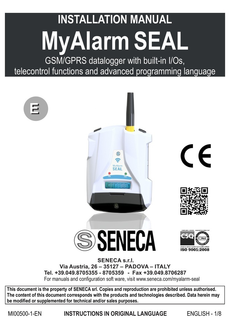
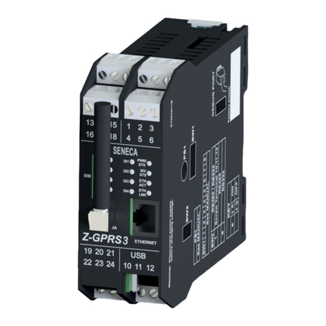
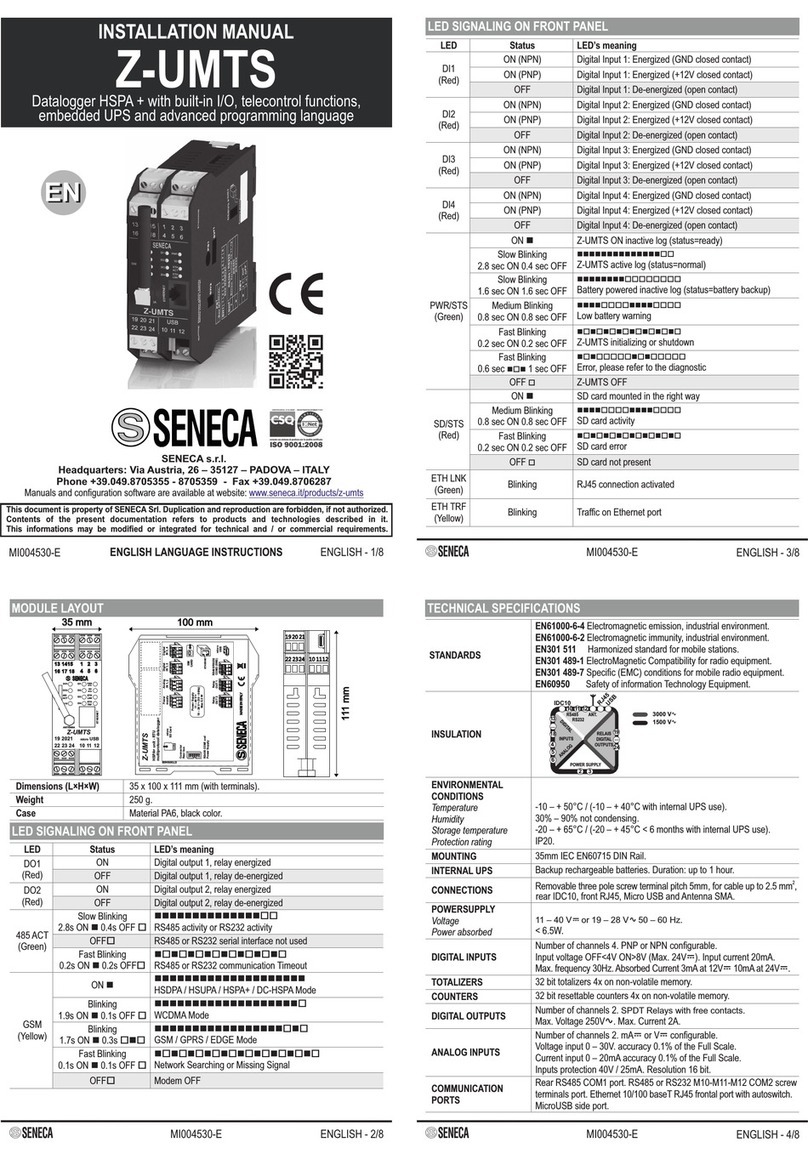
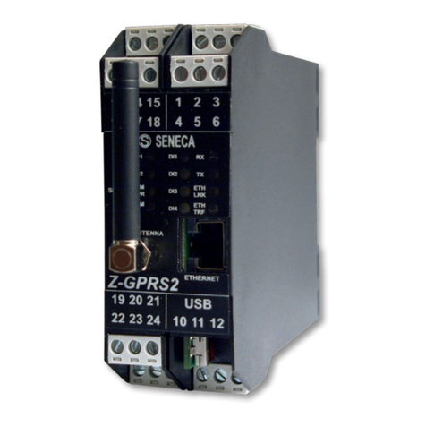
Seneca Z-8R-10A User manual

ITALIANO 1/8
Questo documento è di proprietà SENECA srl. La duplicazione e la riproduzione sono vietate, se non
autorizzate. Il contenuto della presente documentazione corrisponde ai prodotti e alle tecnologie
descritte. I dati riportati potranno essere modificati o integrati per esigenze tecniche e/o commerciali.
MI002242-I
Pag.Indice:
1.0 Disclaimer
2.0 Descrizione e
Caratteristiche generali
2.1 Descrizione
2.2 Caratteristiche generali
3.0 Specifiche tecniche
2.1 Alimentazione
2.2 Relè
2.3 Connettori
2.4 Condizioni ambientali
2.5 Contenitore
2.6 Ingombri
4.0 Istruzioni preliminari di utilizzo
5.0 Collegamenti elettrici
5.1 Installazione su barra DIN46277
5.2 Alimentazione
5.3 Uscita relè
5.4 Connessione dei moduli Seneca
5.4.1. Connessione dello ZC-24DO
5.4.2. Connessione dello ZC-16DI8DO
5.4.3. Connessione dello Z-10-D-OUT
6.0 Corrispondenza tra relè e uscite
digitali dai moduli seneca.
Produttore
Seneca s.r.l.
Via Austria, 26 - 35127 - PADOVA - IT
Tel. +39.049.8705355 - 8705359 - Fax +39.049.8706287
Web
www.seneca.it
Mail
Lingua manuale
Italiano
Prodotto
Z-8R-10A
Funzioni
Scheda relè
3
3
·
MANUALE DI INSTALLAZIONE ED USO
2
2
2
6

1.0 DISCLAIMER
Seneca S.r.l. www.seneca.it
Via Austria, 26 - 35127 - PADOVA - IT
Prima di effettuare qualsiasi operazione è obbligatorio leggere tutto il contenuto
del presente Manuale. Il modulo deve essere utilizzato esclusivamente da
tecnici qualificati nel settore delle installazioni elettriche.
La riparazione del modulo o la sostituzione di componenti danneggiati deve
essere effettuata dal Costruttore.
Le condizioni di garanzia decadono se il modulo è manomesso.
3.0 SPECIFICHE TECNICHE
3.1 Alimentazione
Tensione alimentazione scheda
24 Vdc
Assorbimento
0,5 W
2.0 DESCRIZIONE E CARATTERISTICHE GENERALI
2.1 Descrizione
Scheda con 8 relè, portata 250 Vac, 10 A
2.2 Caratteristiche generali
- Alimentazione 24 Vdc (non obbligatoria)
- Cablaggio facilitato per mezzo del supporto che permette l’installazione su guida DIN.
- Morsetti estraibili a sezione 2.5 mm con passo 5.08 mm
2
- Led di indicazione dello stato del relè e tasti di prova relè
- Connettori specifici per cavi flat in modo da semplificare il cablaggio di moduli Seneca
3.4 Condizioni ambientali
Temperatura
-30 °C.. +70 °C
Umidità
30 ..90% a 40 °C non condensante
Altitudine
Fino a 3000 m sul livello del mare
Temperatura di stoccaggio
-40 .. +85°C
3.3 Connettori
Connettori
IDC da 10, 16(2), 20 poli per cavo flat
Morsetti estraibili passo 3,5 mm
3.2 Relè
Numero relè
8
Portata
250 Vac, 10 A
ITALIANO 2/8
MI002242-I

MI002242-I ITALIANO 3/8
3.6 Ingombri
4.0 ISTRUZIONI PRELIMINARI DI UTILIZZO
Il modulo è progettato per essere installato su guida DIN 46277 (figura 1) in posizione
orizzontale.
È vietato installare il modulo accanto ad apparecchi che generano calore.
5.0 COLLEGAMENTI ELETTRICI
Togliere l’alimentazione dal modulo prima di collegare le uscite.
5.1 Installazione su barra DIN 46277
Per una corretta
installazione:
-Agganciare alla guida DIN
la parte superiore del
gancio.
-Spingere la scheda verso
il basso e premere verso la
guida per agganciare la
parte inferiore del gancio.
3.5 Contenitore
Dimensioni
L: 160 mm x H: 80 mm x W: 46 mm
Contenitore
Polyamide, grigio
160 mm
46 mm 80 mm
CLACK!
1

ITALIANO 4/8
MI002242-I
5.2 Alimentazione
L’alimentazione a 24 Vdc da morsetto 2 vie è facoltativa e può essere usata solo per eseguire
il test di funzionamento dei relè (modalità test).
Lo Z-8R-10A in modalità normale funziona attraverso la sola connessione del cavo flat,
tuttavia è necessario portare alimentazione a 24 Vdc ai morsetti di alimentazione uscite,
presenti nel modulo collegato (Vedi paragrafi 5.4).
Il led verde «PWR» si accenderà se l’Z-8R-10A è alimentata dai 24 Vdc.
Nel caso in cui l’alimentazione provenga sia da modulo seneca che da flat è
possibile eseguire un test di funzionamento dei relè.
Per testare lo Z-8R-10A si deve eseguire nell'ordine le seguenti operazioni:
- Premere uno dei tasti preposti
- Verfificare che il relè corrispondente scatti
- Verificare che il led corrispondente si accenda.
5.3 Uscite relè
E’ possibile connettere le uscite dei relè usando i morsetti a vite.
5.4 Connessioni ai moduli Seneca
E’ possibile pilotare la scheda relè usando i moduli seneca. I moduli seneca appropriati
per questo utilizzo sono:
Z-10-D-OUT
ZC-24DO
ZC-16DI8DO
24 Vdc
+
-
2
N 2O
COM2
RELE 1
N 1O
COM1
N 1A
RELE 2
...
...
3
12345

MI002242-I ITALIANO 5/8
Di seguito verrà illustrato come connettere un modulo seneca alla scheda relè.
5.4.1. Connessione allo ZC-24DO
5.4.2. Connessione dello ZC-16DI8DO
Per connettere le 8 uscite digitali dello ZC-16DI8DO basterà replicare la connessione vista
nello ZC-24DO riguardante la terza scheda Z-8R-10A.
Per connettere le 24 uscite digitale dello ZC-24DO sarà necessario usare 3 Z-8R-10A.
La figura sotto mostra come connettere le 24 uscite digitali dello ZC-24DO con il cavo flat.
Per connettere due Z-8R-10A insieme si raccomanda di leggere la nota in basso.
Per connettere le restanti 8 uscite
digitali dello ZC-24DO è necessario
connettere un’altra scheda relè.
Questo è possibile collegando un
cavo flat al connettore a vaschetta
a 16 poli della scheda relè 1 al
primo connettore a vaschetta a 16
poli della scheda relè 2.
Scheda relè 1
(8 relè)
Scheda relè 2
(8 relè)
Scheda relè 3
(8 relè)
4
Alimentare le
schede relè
tramite i morsetti
8 (+) e 7 (-)
dello ZC-24DO
+
24 Vdc

MI002242-I ITALIANO 6/8
5.4.3. Connessione allo Z-10-D-OUT
Per connettere lo Z-10-D-OUT al Z-8R-10A è necessario usare il cavo a 16 poli
5
Alimentare la
scheda relè
tramite i morsetti
1 (+) e 12 (-)
dello Z-10-D-OUT
+24 Vdc
Modulo Seneca
Uscita digitale
Scheda N°
(Z-8R-10A)
Relè
corrispondente
ZC-24DO
1..8
1
Relay1..8
9..16
2
Relay9..16
16..24
3
Relay17..24
ZC-16DI8DO
1..8
1
Relay1..8
Z-10-D-OUT
1..8
1
Relay1..8
6.0 Corrispondenza tra relè e uscite digitali dai moduli Seneca
Nella tabella sopra è riportata la corrispondenza tra i relè presenti nello Z-8R-10A e le
uscita digitali che provengono dai moduli Seneca.
Per una maggiore chiarezza è disponibile nella pagina seguente la numerazione dei
morsetti e la numerazione dei relè.

MI002242-I ITALIANO 7/8
12345678910 11 121314 1516 171819 202122 23 24
RELE 1 (9/17)
RELE 2 (10/18)
RELE 3 (11/19)
RELE 4 (12/20)
RELE 5 (13/21)
RELE 6 (14/22)
RELE 7 (15/23)
RELE 8 (16/24)
Smaltimento dei rifiuti elettrici ed elettronici (applicabile nell’Unione Europea e negli altri paesi con raccolta
differenziata). Il simbolo presente sul prodotto o sulla confezione indica che il prodotto non verrà trattato come rifiuto
domestico. Sarà invece consegnato al centro di raccolta autorizzato per il riciclo dei rifiuti elettrici ed elettronici.
Assicurandovi che il prodotto venga smaltito in modo adeguato, eviterete un potenziale impatto
negativosull’ambiente e la salute umana, che potrebbe essere causato da una gestione non conforme dello
smaltimento del prodotto. Il riciclaggio dei materiali contribuirà alla conservazione delle risorse naturali. Per ricevere
ulteriori informazioni più dettagliate Vi invitiamo a contattare l’ufficio preposto nella Vostra città, il servizio per lo
smaltimento dei rifiuti o il fornitore da cui avete acquistato il prodotto.

Questa pagina è stata intenzionalmente lasciata vuota.
MI002242-I ITALIANO 8/8

MI002242-I-E ENGLISH 1/8
This document is property of SENECA srl. Duplication and reprodution are forbidden, if not authorized. Contents of
the present documentation refers to products and technologies described in it. All technical data contained in the
document may be modified without prior notice Content of this documentation is subject to periodical revision.
Contents:
1.0 Disclaimer
2.0 Description and
General specifications
2.1 Description
2.2 General specifications
3.0 Technical specifications
2.1 Power supply
2.2 Relays
2.3 Connector
2.4 Environmental condition
2.5 Box
2.6 Dimension
4.0 Perliminary instruction for use
5.0 Electrical connections
5.1 Installation on DIN46277 rail
5.2 Power supply
5.3 Relays output connection
5.4 Connection of Seneca module
5.4.1. Connectioin of ZC-24DO
5.4.2. Connection of ZC-16DI8DO
5.4.3. Connection of Z-10-D-OUT
6.0 C between relaysorrespondence
and Seneca digital outputs
modules.
Language manual
English
Product
Z-8R-10A
Description
Relays board
Manufacturer
Seneca s.r.l.
Via Austria, 26 - 35127 - PADOVA - IT
Tel. +39.049.8705355 - 8705359 - Fax +39.049.8706287
Web
www.seneca.it
Mail
·
INSTALLATION AND USER’S GUIDE
Pag.
3
3
2
2
2
6

MI002242-I-E ENGLISH 2/8
1.0 DISCLAIMER
Seneca S.r.l. www.seneca.it
Via Austria, 26 - 35127 - PADOVA - IT
Before executing any operation it’s mandatory to read all the content of this
user manual. Only electrical-skilled technicians can use the module
described in this user Manual.
Only the Manufacturer is authorized to repair the module or to replace
damaged components.
No warranty is guaranteed in connection with faults resulting from improper
use, from modifications or repairs carried out by Manufacturer-unauthorised
personnel on the module, or if the content of this user Manual is not followed.
3.0 TECHNICAL SPECIFICATIONS
3.1 Power supply
Voltage supply
24 Vdc
Consumption
0,5 W
2.0 DESCRIPTION AND GENERAL SPECIFICATIONS
2.1 Description
8 relais on PCB with carrying capacity of 250 Vac, 10 A
2.2 General specifications
- Power supply of 24 Vdc.
- Easy connection on din rail by rear support.
- Screw terminal with section 2.5 mm ,pitch 5.08 mm
2
- Signallings of relay status from led
- Easy connection for seneca module by a specific connector for flat cable
3.4 Environmental condition
Temperture
-30 °C.. +70 °C
Humidity
30 ..90% a 40 °C noncondensing
Altitude
Up to 3000 m above sea level
Storage temperature
-40 .. +85°C
3.3 Connector
Connector
IDC 10, 16(2), 20 pins for flat cable
Screw terminals pitch 3,5 mm
3.2 Relays
Number
8
Carrying capacity
250 Vac, 10 A

MI002242-I-E ENGLISH 3/8
3.6 Dimension
4.0 PRELIMINARY INSTRUCTION FOR USE
The module is designed to be installed on DIN 46277 rail in horizontal position (see
picture 1).
It is forbidden to install the module near heat sources.
5.0 ELECTRICAL CONNECTIONS
Power off the module before connecting the relays output.
5.1 Installation on DIN 46277 rail
For a proper installation:
-Attach to the DIN rail the
top of the rear support .
-Push down the relays
board and press towards
the din rail to hook the
bottom of the rear support
3.5 Box
Dimension
L: 160 mm x H: 80 mm x W: 46 mm
Box
Polyamide, grey
160 mm
46 mm 80 mm
CLACK!
1

MI002242-I-E ENGLISH 4/8
5.2 Power supply
The 2-way screw terminal is only suitable to provided a 24 Vdc power supply to used Z-8R-
10Ain order to execute a relay test (modality test), optional connection.
Otherwise in the normal modality the Z-8R-10A only must use the flat cable connection,
althought the 24 Vdc must be provided to digital output screw terminals of connected
module.(see par. 5.4)
If the Z-8R-10A is powered correctly the green led «PWR» will light.
If the supply comes from Seneca’s module and from flat it is possible to execute
a test of relays operations.
To test the Z-8R-10A, execute in the order the following operations:
- Push an button
- Verify that the corrisponding relay functions properly
- Verify that the corrisponding led is on.
5.3 Relay output connection
It’s possible to connect the outputs relay by use the screw terminal connectors.
5.4 Connection to the seneca module
The connected Seneca module can control the Z-8R-10A.
Use the following Seneca module to control the Z-8R-10A:
Z-10-D-OUT
ZC-24DO
ZC-16DI8DO
N 2O
COM2
RELAY 1
N 1O
COM1
N 1C
RELAY 2
...
...
3
24 Vdc
+
-
2

MI002242-I-E ENGLISH 5/8
In the following paragraphs you will learn how to connect a Seneca module to the Z-8R-
10A.
5.4.1. Connection to ZC-24DO
5.4.2. Connection to ZC-16DI8DO
To connect 8 digital outputs of the ZC-16DI8DO, replicate the connection saw in the ZC-
24DO in the third Z-8R-10A.
To connect all 24 digital outputs will need to use 3 Z-8R-10A. The picture below shows
how to connect the 24 digital outputs of ZC-24DO to the 3 Z-8R-10A with the flat cables.
Read the note below to know how to connect two Z-8R-10A together.
To connect the 16 digital outputs
is necessary to connect two Z-8R-10A
together.
This is made possible connecting an
appropriate flat cable with 16 pins
connected from the first Z-8R-10A to
the 16 pins connector on the second
Z-8R-10A as shows in the picture.
First PCB relais
(8 relais)
Second PCB relais
(8 relais)
Third PCB relais
(8 relais)
4
+
The power supply
for the Z-8R-10A
must come from
the 8 (+) and 7(-)
screw terminals of
ZC-24DO.
24 Vdc

5.4.3. Connection to Z-10-D-OUT
MI002242-I-E ENGLISH 6/8
To connect the Z-10-D-OUT to the Z-8R-10A use the flat cable with 16 pins
5
+
The power supply
for the Z-8R-10A
must come from
the 1 (+) and 12(-)
screw terminals of
Z-10-D-OUT.
24 Vdc
6.0 Correspondence between relays and Seneca digital outputs modules.
The table above shown the correspondence between the relays on Z-8R-10A and the
digital outputs came from Seneca's module.
The picture of Z-8R-10A in the following page shows the screw terminals and relays
numbering.
Seneca's module
Digital Output
Board N°
(Z-8R-10A)
Relays
Correspondence
ZC-24DO
1..8
1
Relay1..8
9..16
2
Relay9..16
16..24
3
Relay17..24
ZC-16DI8DO
1..8
1
Relay1..8
Z-10-D-OUT
1..8
1
Relay1..8

ENGLISH 7/8
MI002242-I-E
Disposal of Electrical & Electronic Equipment (Applicable throughout the European Union and other European
countries with separate collections programs). This symbol, found on your producr or on its packaging, indicates that
this product should not be treated as household waste when you wish to dispose of it. Instead, it should be handed
over to an applicable collection point for the recycling of electrical & electronic equipment. By ensuring this product is
didposed of correctly, you will help prevent potential negative consequences to the environment and human health,
which could otherwise be caused by inappropriate disposal of this product. The recycling of materials will help to
conserve natural resources. For more detailed information about the recycling of the product, please contact your
local city office, waste disposal service of the retail store where you purchased this product.
12345678910 11 121314 15 16 171819 202122 23 24
RELAY 1 (9/17)
RELAY 2 (10/18)
RELAY 3 (11/19)
RELAY 4 (12/20)
RELAY 5 (13/21)
RELAY 6 (14/22)
RELAY 7 (15/23)
RELAY 8 (16/24)

ENGLISH 8/8
MI002242-I-E
This page intentionally left blank.

FRANÇAIS 1/8
Ce document est la propriété de SENECA srl. Il est interdit de le copier ou de le reproduire sans
autorisation. Le contenu de la présente documentation correspond aux produits et aux technologies
décrites. Les données reportées pourront être modifiées ou complétées pour des exigences techniques
et/ou commerciales.
MI002242-F
Pag.sommaire
1.0 Disclaimer
2.0 Description et
caractéristiques générales
2.1 Description
2.2 caractéristiques générales
3.0 Caractéristiques techniques
2.1 Alimentation
2.2 relais
2.3 connecteurs
2.4 Conditions ambiantes
2.5 boîtier
2.6 encombrements
4.0 Instructions préliminaires d'utilisation
5.0 Branchements électriques
5.1 Montage sur barre DIN46277
5.2 alimentation
5.3 Sortie relais
5.4 Connexion des modules Seneca
5.4.1. Connexion du ZC-24DO
5.4.2. Connexion du ZC-16DI8DO
5.4.3. Connexion du Z-10-D-OUT
6.0 Correspondance entre relais et
sorties numériques des modules
seneca.
Fabricant
Seneca s.r.l.
Via Austria, 26 - 35127 - PADOVA - IT
Tel. +39.049.8705355 - 8705359 - Fax +39.049.8706287
Web
www.seneca.it
Mail
Langue du manuel
FRANÇAIS
produit
Z-8R-10A
fonctions
Carte relais
3
3
·
Manuel de montage et d'utilisation
2
2
2
6

1.0 Disclaimer
Seneca S.r.l. www.seneca.it
Via Austria, 26 - 35127 - PADOVA - IT
Avant de faire une opération quelconque, lire obligatoirement le contenu du
présent Manuel. Le module ne doit être utilisé que par des techniciens qualifiés
dans le secteur des installations électriques.
Seul le fabricant peut réparer le module ou remplacer les composants
abîmés.
Il y a déchéance des conditions de garantie si le module a été altéré.
3.0 Caractéristiques techniques
3.1 Alimentation
Tension d'alimentation carte
24 Vdc
Absorption
0,5 W
2.0 Description et caractéristiques générales
2.1 Description
Carte avec 8 relais, débit 250 Vca, 10 A
2.2 caractéristiques générales
- Alimentation 24 Vcc (pas obligatoire)
- Câblage facilité à l'aide du support qui permet le montage sur un guide DIN.
- Bornes amovibles section 2,5 mm² avec pas 5,08 mm
- Dels indiquant l'état du relais et touches d'essai relais
- Connecteurs spécifiques pour câbles plat afin de simplifier le câblage des modules
Seneca
3.4 Conditions ambiantes
-30 °C.. +70 °C
-40 .. +85°C
3.3 connecteurs
Connecteurs
IDC de 10, 16(2), 20 pôles pour câble plat
Bornes amovibles pas 3,5 mm
3.2 relais
Nombre de relais
8
Débit
250 Vac, 10 A
FRANÇAIS 2/8
MI002242-F
température
humidité 30 ..90% a 40°C sans condensation
Altitude jusqu'à 3 000 m au-dessus du niveau de la mer
Température de stockage

MI002242-F FRANÇAIS 3/8
3.6 encombrements
4.0 Instructions préliminaires d'utilisation
Le module a été conçu pour être monté à l'horizontale sur un guide DIN 46277 (figure 1).
Il est interdit de monter le module à proximité d'appareils qui dégagent de la
chaleur.
5.0 Branchements électriques
Interrompre l'alimentation du module avant de brancher les sorties
5.1 Montage sur barre DIN46277
Pour un montage correct :
-Fixer la partie supérieure
du crochet au guide DIN.
-Pousser la carte vers le
bas et appuyer sur le guide
pour fixer la partie
inférieure du crochet.
3.5 boîtier
L: 160 mm x H: 80 mm x W: 46 mm
Polyamide, gris
160 mm
46 mm 80 mm
CLACK!
1
dimensions
Boîtier

FRANÇAIS 4/8
MI002242-F
5.2 alimentation
L'alimentation en 24 Vcc à partir de la borne à 2 voies est facultative et ne peut être utilisée
que pour exécuter le test de fonctionnement des relais (mode test).
Z-8R-10A fonctionne en mode normal uniquement grâce à la connexion du câble plat, il est
toutefois nécessaire de porter le courant en 24 Vcc aux bornes d'alimentation des sorties,
présentes dans le module relié (Voir paragraphes 5.4).
La del verte «PWR» s'allume si Z-8R-10A est alimenté en 24 Vcc.
Si l'alimentation provient aussi bien du module seneca que du câble plat, il est
possible de faire un test de fonctionnement des relais.
Pour tester Z-8R-10°, faire les opérations suivantes dans l'ordre :
- Appuyer sur une des touches prévues à cet effet
- Vérifier si le relais correspondant se déclenche
- Vérifier si la del correspondante s'allume.
5.3 Sortie relais
Il est possible de brancher les sorties des relais en utilisant les bornes à vis.
5.4 Connexion des modules Seneca
Il est possible de commander la carte relais en utilisant les modules seneca. Les modules
seneca appropriés pour cette utilisation sont :
Z-10-D-OUT
ZC-24DO
ZC-16DI8DO
24 Vdc
+
-
2
N 2O
COM2
RELAY 1
N 1O
COM1
N 1A
RELAY 2
...
...
3
12345
Table of contents
Languages:
Other Seneca Data Logger manuals

Seneca
Seneca MyALARM2 User manual

Seneca
Seneca Z-LOGGER User manual

Seneca
Seneca Z-LTE User manual

Seneca
Seneca Z-LTE User manual

Seneca
Seneca Z-UMTS User manual

Seneca
Seneca Z-UMTS User manual

Seneca
Seneca Z-LOGGER3 User manual

Seneca
Seneca Z-UMTS HW2 User manual

Seneca
Seneca Z-GPRS3 HW2 User manual

Seneca
Seneca MyALARM2-4G User manual