FC/FCA Charger Operation & Maintenance – 6 & 10 amp units
5
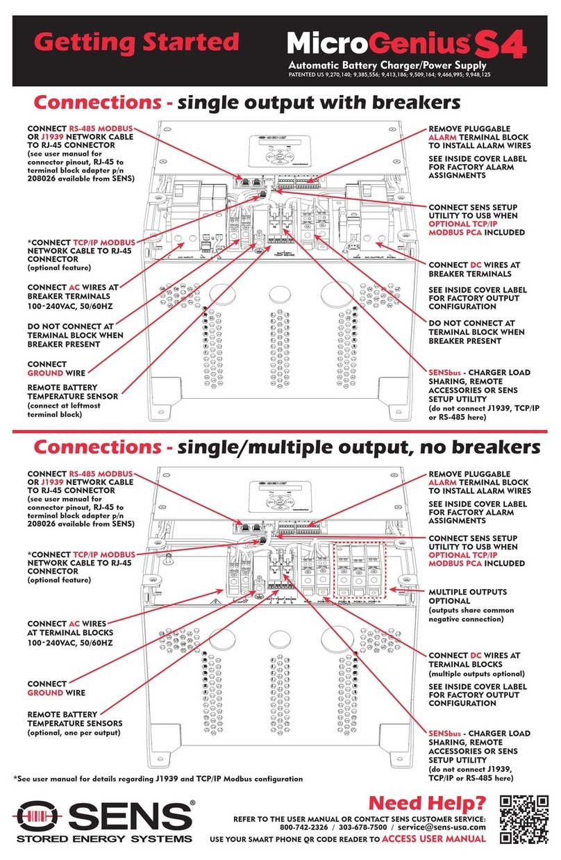
Refer to the drawings at the back of this guide. Connection should be made by a qualified installer.
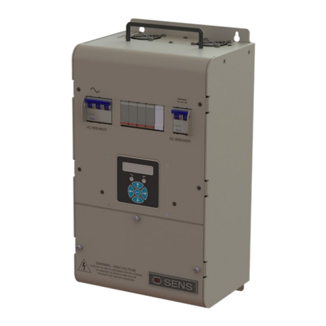
Remove the two screws securing the charger's top front panel to gain access to the connections.
• Use AWG #12 or larger wire rated for 90C temperature or higher for DC (charger to battery)
leads.
• Use AWG #14 or larger wire rated for 90C temperature or higher for AC input and ground
connections
WARNING: The battery charger should be connected to a grounded permanent wiring system. A
ground stud is provided for this purpose
Knockouts accommodating 1/2" conduit and fittings are located on each side of the charger. Run
the AC wiring independent of the DC and alarm wiring.
The voltmeter will show battery voltage as soon as the DC connection is completed. Check the
voltmeter as soon as the FC connection has been made. If the meter reads zero or is deflecting
below zero, reverse the polarity of the battery connections. Do not energize the charger with the
battery connected backwards--the DC fuse will blow.
3.3 Alarm Connections (pertains only to FCA models)
Caution: Connection to the alarms is somewhat delicate; complete instructions and detailed
drawings are provided at the end of this guide. Use stranded wire, rather than solid, if it is
available.
The alarm relays are rated for a maximum of 2 amps at 25 volts DC, or 0.5 amp at 120 volts AC
(non-inductive loads only). Connect the alarm relay to customer-supplied supervisory system only
-- do not apply AC mains power to the relays and do not exceed the relays’ ratings.
Two versions of FCA alarm board are available:
Condition LED Indicator FCA model suffix
AC on Green LED -2211, -2411
Low battery voltage Amber LED -2211, -2411
Charger failure Red LED -2211, -2411
AC fail Red LED -2411 only
High battery voltage Red LED -2411 only
4
Using the
Charger
4.1 Features of the Charger
FC/FCA chargers feature soft start circuitry which causes a gradual increase in output power after
application of AC power. The Autoboost system causes the charger initially to operate at the high
rate. When the charger reaches the boost voltage set point, and current has dropped to approximately
50% to 70% of the charger's rating, the charger will revert to the float mode. The transition from
boost to float will cause the output current of the charger to drop to zero amps until the battery
voltage drops to the float level. Once the battery voltage nears the float setting, the charger will
again deliver a small amount of current to the battery to maintain it at its fully charged state. Figure
3 is a graph of how the Autoboost system works.
NOTE: Autoboost is disabled on chargers shipped for use with sealed lead-acid batteries, per the
recommendation of most battery manufacturers.
The battery charger is temperature compensated to match the negative temperature coefficient of
the battery. Thus the float voltage will increase slightly as the temperature decreases, and decrease
as temperature increases. The battery charger is electronically current limited to 110% of rated
output. The charger will reduce its current output when the battery voltage is lower than normal so


