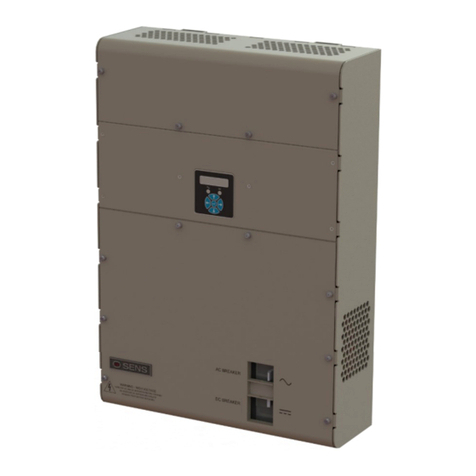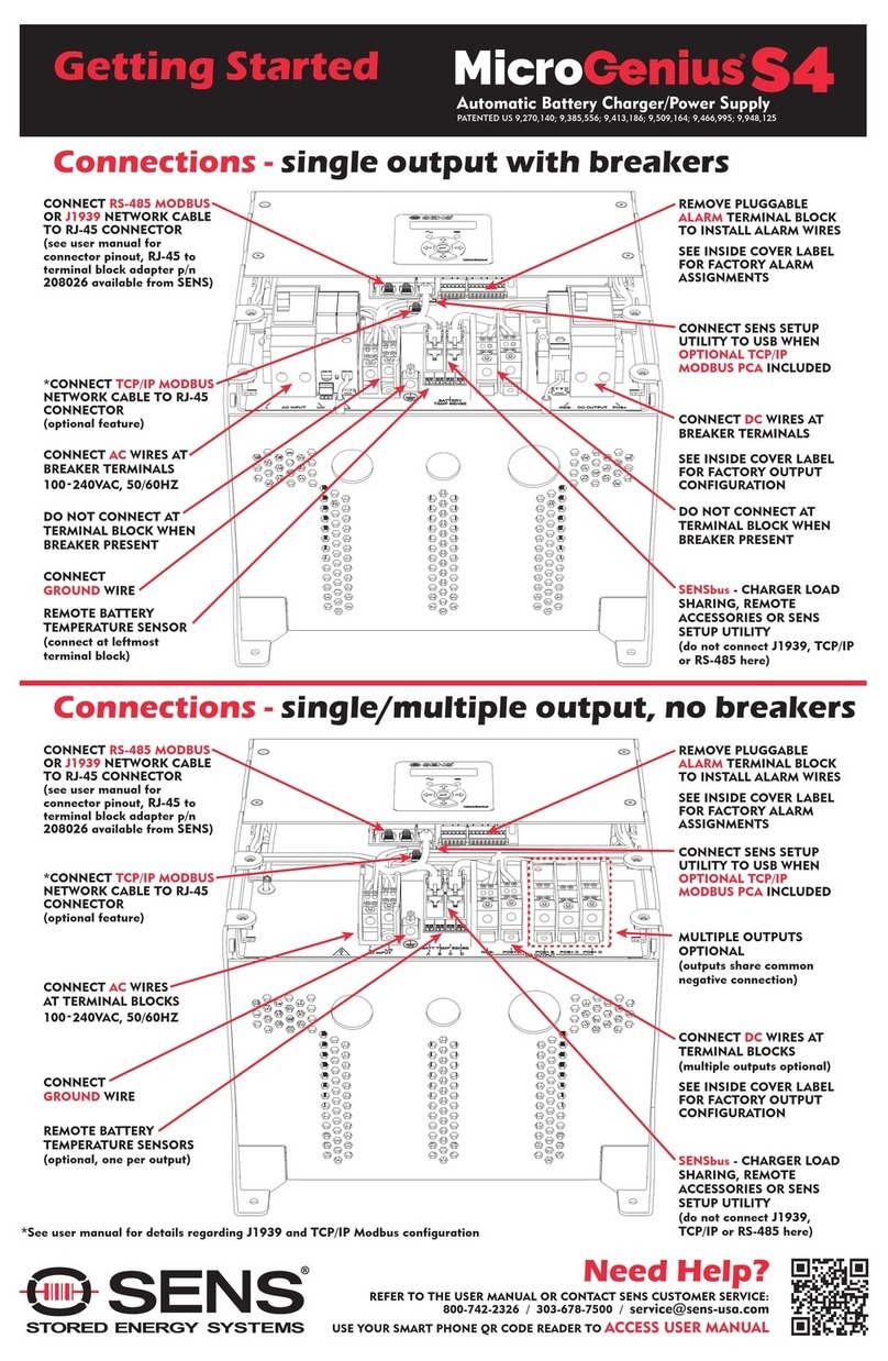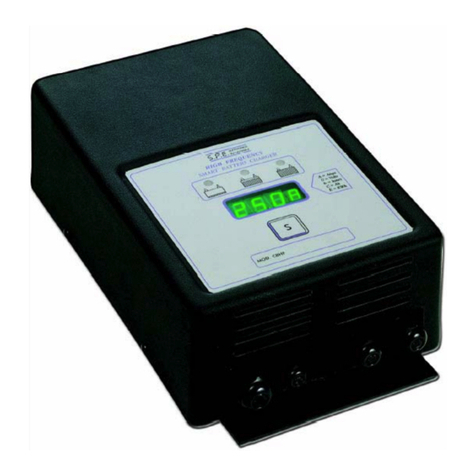
SENS MicroGenius S2/S4 Technical Manual
2
TABLE OF CONTENTS
1IMPORTANT SAFETY INSTRUCTIONS FOR INSTALLER AND OPERATOR................................................................................ 3
2MODEL NUMBER BREAKOUT................................................................................................................................................. 5
3PERFORMANCE SPECIFICATIONS ........................................................................................................................................... 6
4SYSTEM OVERVIEW.............................................................................................................................................................. 10
5MOUNTING INSTRUCTIONS ................................................................................................................................................. 13
5.1. Mounting Location .....................................................................................................................................................13
5.2. Mounting Instructions................................................................................................................................................13
6SETUP AND WIRING ............................................................................................................................................................. 14
6.1. Wire Ratings and Sizes ...............................................................................................................................................14
6.2. Grounding Instructions and Connection ....................................................................................................................15
6.3. DC Connection............................................................................................................................................................15
6.4. AC Connection............................................................................................................................................................17
6.5. Alarm Connections.....................................................................................................................................................17
6.6. Remote Temperature Sensor Connection—Optional ................................................................................................19
6.7. SAE J1939 Communications Setup (CANbus) .............................................................................................................20
6.8. Modbus Communications Setup ................................................................................................................................21
6.9. Load Share Connection—Optional .............................................................................................................................22
6.10. Remote Alarm/Communications Panel Accessory Connection—Optional ................................................................23
6.11. Verify Connections .....................................................................................................................................................23
7START-UP PROCEDURE......................................................................................................................................................... 23
7.1. Connect Battery/Outputs...........................................................................................................................................23
7.2. Verify Configuration ...................................................................................................................................................23
7.3. Apply AC Input Voltage ..............................................................................................................................................24
7.4. Power Off ...................................................................................................................................................................24
8ALARMS, LEDS AND DISPLAY ............................................................................................................................................... 24
8.1. LED Indicators.............................................................................................................................................................24
8.2. Individual Alarm Relay Contacts.................................................................................................................................25
8.3. LCD Panel ...................................................................................................................................................................26
8.4. Alarm Definitions .......................................................................................................................................................26
9OPERATION .......................................................................................................................................................................... 32
9.1. Charging Algorithms................................................................................................................................................... 32
9.2. Float Mode .................................................................................................................................................................33
9.3. Dynamic Boost™ Mode ..............................................................................................................................................33
9.4. HELIX Mode................................................................................................................................................................34
9.5. Ultracapacitor Mode ..................................................................................................................................................34
9.6. Charging Low or Zero-volt Batteries...........................................................................................................................34
9.7. Commissioning Batteries............................................................................................................................................35
9.8. Battery Check ............................................................................................................................................................. 35
9.9. Restore Factory Defaults............................................................................................................................................35
9.10. Keypad Operation ......................................................................................................................................................36
9.11. Configuration with SENS Setup Utility........................................................................................................................40
9.12. Temperature Compensation ......................................................................................................................................40
9.13. Load Share Charger Operation...................................................................................................................................41
9.14. Remote Alarm/Communications Panel Accessory .....................................................................................................42
10 J1939 COMMUNICATIONS ................................................................................................................................................... 42
10.1. J1939 Data Messages .................................................................................................................................................42
11 MODBUS COMMUNICATIONS............................................................................................................................................. 43
11.1. TCP/IP Modbus........................................................................................................................................................... 43
11.2. Modbus Holding Registers .........................................................................................................................................44
11.3. Status Definition.........................................................................................................................................................54
11.4. Alarm Bit Definition....................................................................................................................................................54
11.5. Extended Status Bit Definition ...................................................................................................................................55
11.6. Writable Control Flags (Coils).....................................................................................................................................56
12 TROUBLESHOOTING/ERROR CODES .................................................................................................................................... 57
12.1. Configuration Error Codes..........................................................................................................................................57
12.2. Troubleshooting .........................................................................................................................................................59
13 GLOSSARY............................................................................................................................................................................. 63


