SENS EnerGenius IQ2 Technical Manual
2
TABLE OF CONTENTS
1IMPORTANT SAFETY INSTRUCTIONS FOR INSTALLER AND OPERATOR ..........................................................4
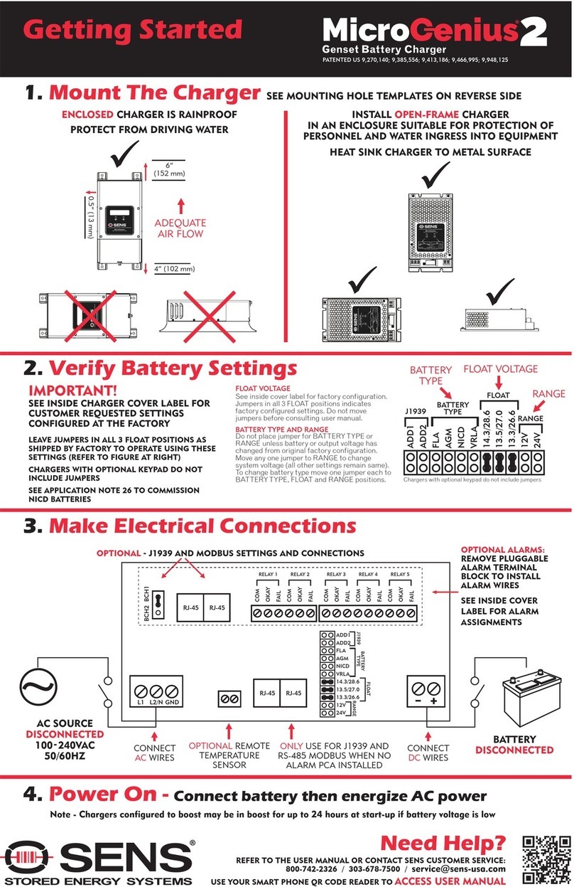
2QUICK INSTALLATION GUIDE ........................................................................................................................6
3PERFORMANCE SPECIFICATIONS...................................................................................................................7
4MODEL NUMBER BREAKOUT ........................................................................................................................8
5MECHANICAL INSTALLATION ........................................................................................................................9
5.1. Lifting...................................................................................................................................................9
5.2. Charger Mounting Options ...................................................................................................................9
5.3. Ventilation ...........................................................................................................................................9
5.4. Environmental Considerations..............................................................................................................9
6ELECTRICAL INSTALLATION ...........................................................................................................................9
6.1. AC Input Connections...........................................................................................................................9
6.2. DC Output Connections......................................................................................................................11
6.3. Alarm Wiring......................................................................................................................................12
6.4. Operating Chargers in Parallel.............................................................................................................14
6.5. CANbus and RS-485 Connections—Optional .......................................................................................14
6.6. Ethernet—Optional ............................................................................................................................16
6.7. SENSbus Connection—Optional..........................................................................................................17
6.8. Remote Temperature Sensor Connection—Optional...........................................................................19
7POWER ON/POWER OFF PROCEDURES....................................................................................................... 20
7.1. Verify Input AC Supply........................................................................................................................20
7.2. Verify Configuration ...........................................................................................................................20
7.3. Verify Charger Output.........................................................................................................................21
7.4. Begin Charging ...................................................................................................................................21
7.5. Power Off...........................................................................................................................................21
8ALARMS, LEDS AND DISPLAY....................................................................................................................... 22
8.1. Front Panel User Interface..................................................................................................................22
8.2. LCD Panel...........................................................................................................................................22
8.3. AC and DC LED Indicators ...................................................................................................................22
8.4. Mimic Panel LEDs...............................................................................................................................23
8.5. Individual Alarm Relay Contacts..........................................................................................................24
8.6. Latched Alarms...................................................................................................................................24
8.7. Alarm Definitions ...............................................................................................................................24
9OPERATION................................................................................................................................................. 31
9.1. Charging Algorithms...........................................................................................................................31
9.2. Float Mode.........................................................................................................................................31
9.3. Dynamic Boost™ Mode.......................................................................................................................31
9.4. HELIX Mode........................................................................................................................................32
9.5. Charging Low or Zero-volt Batteries....................................................................................................32
9.6. Commissioning Batteries ....................................................................................................................33
9.7. Battery Check.....................................................................................................................................33
9.8. Restore Factory Defaults ....................................................................................................................33
9.9. Keypad Operation ..............................................................................................................................33
9.9.3. Menu Options ....................................................................................................................................34
9.10. Configuration with SENS Setup Utility.................................................................................................39
9.11. Temperature Compensation...............................................................................................................39
9.12. Load Share Charger Operation............................................................................................................40
10 MODBUS COMMUNICATIONS..................................................................................................................... 40
10.1. TCP/IP Modbus—Optional..................................................................................................................40
10.2. RS-485 Modbus—Optional .................................................................................................................40
10.3. Modbus Holding Registers..................................................................................................................41
10.4. Basic Charging Alarms Bit Definition ...................................................................................................42
10.5. Charging Status Bit Definition .............................................................................................................43
10.6. Charging Alarms Extended Bit Definition.............................................................................................44
10.7. Charging AC Alarms Bit Definition.......................................................................................................44
10.8. Accessory Channel Alarms Bit Definition.............................................................................................44


