SENSTAR FlexPS User manual

Product
Guide
FlexPS®
Fence-mounted Perimeter Intrusion Detection Sensor
G5DA0102-001 Rev G
July 8, 2015

Page 2 FlexPS Product Guide
Senstar Corporation
Website: www.senstar.com
Email address: info@senstar.com
G5DA0102-001 Rev G
July 8, 2015
FlexPS, Senstar and the Senstar logo are registered trademarks, and Armour-FLEX, Silver Network, and Crossfire are
trademarks of Senstar Corporation. Product names and Company names included in this document are used only for
identification purposes and are the property of, and may be trademarks of, their respective owners. Copyright © 2015, 2011,
Senstar Corporation, all rights reserved. Printed in Canada.
The information provided in this guide has been prepared by Senstar Corporation to the best of its ability. Senstar Corporation is
not responsible for any damage or accidents that may occur due to errors or omissions in this guide. Senstar Corporation is not
liable for any damages, or incidental consequences, arising from the use of, or the inability to use, the software and equipment
described in this guide. Senstar Corporation is not responsible for any damage or accidents that may occur due to information
about items of equipment or components manufactured by other companies. Features and specifications are subject to change
without notice.
The figures included in this document are for illustration purposes only, and may differ from the actual equipment.
Approvals
Note: This equipment has been tested and found to comply with the limits for a Class A digital device, pursuant to part 15 of the
FCC Rules. These limits are designed to provide reasonable protection against harmful interference when the equipment is
operated in a commercial environment. This equipment generates, uses and can radiate radio frequency energy and, if not
installed and used in accordance with the instruction manual, may cause harmful interference to radio communications.
Operation of this equipment in a residential area is likely to cause harmful interference in which case the user will be required to
correct the interference at his own expense.
This device complies with part 15 of the FCC Rules. Operation is subject to the following two conditions: (1) This device may not
cause harmful interference, and (2) this device must accept any interference received, including interference that may cause
undesired operation.
Any changes or modifications to the software or equipment that are not expressly approved by Senstar Corporation void the
manufacturer’s warranty, and could void the user’s authority to operate the equipment.
Europe:
This device conforms to EN 61000-6-4: 2001 relating to Electromagnetic compatibility for emission standards for industrial
environments.
This device conforms to EN 50130-4: 1995 + amendments A1: 1998 & A2: 2003 relating to Electromagnetic compatibility for
immunity requirements for components of fire, intruder, and social alarm systems.
The use of shielded cables is required for compliance.
Senstar Corporation’s Quality Management System is ISO 9001:2008 registered.
Service statement - We ensure that our products are correctly applied to achieve the maximum benefits for the end-user. We
work hand-in-hand with our customers and remain accessible through all stages of a project - from concept to deployment to
long-term support. We provide design assistance, site surveys, installation support, comprehensive documentation, training,
post-installation annual calibration and maintenance visits, electronics and software extended warranty, rapid factory repair
service and on-call/emergency service. Contact Senstar Corporation to inquire about how a package can be customized for
your unique applications.

FlexPS Product Guide Page 3
Table of Contents
1 System planning - - - - - - - - - - - - - - - - - - - - - - - - - - - - - - - -7
Introduction - - - - - - - - - - - - - - - - - - - - - - - - - - - - - - - - - - - - - - - - - 7
Installation overview - - - - - - - - - - - - - - - - - - - - - - - - - - - - - - - - - - - - 7
Security factors - - - - - - - - - - - - - - - - - - - - - - - - - - - - - - - - - - - - - -8
Fence structures - - - - - - - - - - - - - - - - - - - - - - - - - - - - - - - - - - - - -8
Standard fence types - - - - - - - - - - - - - - - - - - - - - - - - - - - - - - - - - - - 9
Chain-link fence - - - - - - - - - - - - - - - - - - - - - - - - - - - - - - - - - - - - - - - - - - - 9
Weld-mesh fences - - - - - - - - - - - - - - - - - - - - - - - - - - - - - - - - - - - - - - - - - 9
Palisade fences - - - - - - - - - - - - - - - - - - - - - - - - - - - - - - - - - - - - - - - - - - - 9
Climb-over deterrent hardware - - - - - - - - - - - - - - - - - - - - - - - - - - - - - 9
Razor ribbon - - - - - - - - - - - - - - - - - - - - - - - - - - - - - - - - - - - - - - - - - - - - 10
Gates - - - - - - - - - - - - - - - - - - - - - - - - - - - - - - - - - - - - - - - - - - - - - 11
Other structures - - - - - - - - - - - - - - - - - - - - - - - - - - - - - - - - - - - - - - 11
Environment - - - - - - - - - - - - - - - - - - - - - - - - - - - - - - - - - - - - - - - - - 11
Site Survey - - - - - - - - - - - - - - - - - - - - - - - - - - - - - - - - - - - - - - - - 12
Perimeter layout guidelines - - - - - - - - - - - - - - - - - - - - - - - - - - - - 13
Sensor cable selection rules - - - - - - - - - - - - - - - - - - - - - - - - - - - - - 13
Cable layout guidelines - - - - - - - - - - - - - - - - - - - - - - - - - - - - - - - - - 14
Cable length calculator - - - - - - - - - - - - - - - - - - - - - - - - - - - - - - - - - - - - - 15
Fence height recommendations - - - - - - - - - - - - - - - - - - - - - - - - - - - - - - - 15
Fence corners and heavier gauge posts - - - - - - - - - - - - - - - - - - - - - - - - - 16
Service loops - - - - - - - - - - - - - - - - - - - - - - - - - - - - - - - - - - - - - - - - - - - - 16
Drip loops - - - - - - - - - - - - - - - - - - - - - - - - - - - - - - - - - - - - - - - - - - - - - - 16
Non-sensitive lead-in cable (MEX sensor cable) - - - - - - - - - - - - - - - - - - - 17
Non-sensitive lead-in cable (Mark 2 sensor cable) - - - - - - - - - - - - - - - - - - 17
Gate bypass - - - - - - - - - - - - - - - - - - - - - - - - - - - - - - - - - - - - - - - - - - - - 17
Gate bypass modules - - - - - - - - - - - - - - - - - - - - - - - - - - - - - - - - - - - - - - 17
Armour-FLEX - - - - - - - - - - - - - - - - - - - - - - - - - - - - - - - - - - - - - - - - - - - - 19
Processor location guidelines - - - - - - - - - - - - - - - - - - - - - - - - - - - - 19
AC/DC Power source and wiring - - - - - - - - - - - - - - - - - - - - - - - - - - - - - - 19
Power over Ethernet - - - - - - - - - - - - - - - - - - - - - - - - - - - - - - - - - - - - - - - 20
Grounding considerations - - - - - - - - - - - - - - - - - - - - - - - - - - - - - - - - - - - 21
Alarm monitoring - - - - - - - - - - - - - - - - - - - - - - - - - - - - - - - - - - - - - - - - - 21
Auxiliary inputs - - - - - - - - - - - - - - - - - - - - - - - - - - - - - - - - - - - - - - - - - - - 21
NM Mode - - - - - - - - - - - - - - - - - - - - - - - - - - - - - - - - - - - - - - - - - - - - - - 21
Audio listen-in - - - - - - - - - - - - - - - - - - - - - - - - - - - - - - - - - - - - - - - - - - - 21
Cable connectors - - - - - - - - - - - - - - - - - - - - - - - - - - - - - - - - - - - - - 22
Equipment requirements - - - - - - - - - - - - - - - - - - - - - - - - - - - - - - 22

Page 4 FlexPSProductGuide
2 Installation - - - - - - - - - - - - - - - - - - - - - - - - - - - - - - - - - - -23
Installing the sensor cable - - - - - - - - - - - - - - - - - - - - - - - - - - - - - -23
Cable handling rules - - - - - - - - - - - - - - - - - - - - - - - - - - - - - - - - - - - -23
Mark 2 cable conditioning - - - - - - - - - - - - - - - - - - - - - - - - - - - - - - - -24
Cable conditioning procedure (part 1 - loosening the center conductor) - - 24
Cable conditioning procedure (part 2 - cable flossing) - - - - - - - - - - - - - - - 25
Installing cable on chain-link fences - - - - - - - - - - - - - - - - - - - - - - - - -26
Bend radius - - - - - - - - - - - - - - - - - - - - - - - - - - - - - - - - - - - - - - - - - - - - 27
At fence posts - - - - - - - - - - - - - - - - - - - - - - - - - - - - - - - - - - - - - - - - - - - 28
At corners or heavier gauge posts - - - - - - - - - - - - - - - - - - - - - - - - - - - - - 28
Service loops - - - - - - - - - - - - - - - - - - - - - - - - - - - - - - - - - - - - - - - - - - - 28
Sensor cable overlaps - - - - - - - - - - - - - - - - - - - - - - - - - - - - - - - - - - - - - 29
Installing cable on chain-link - - - - - - - - - - - - - - - - - - - - - - - - - - - - - - - - - 30
Drip loops - - - - - - - - - - - - - - - - - - - - - - - - - - - - - - - - - - - - - - - - - - - - - - 30
Installing terminators - - - - - - - - - - - - - - - - - - - - - - - - - - - - - - - - - - - -31
Installing terminators on MEX cable - - - - - - - - - - - - - - - - - - - - - - - - - - - 31
Installing terminators on Mark 2 cable - - - - - - - - - - - - - - - - - - - - - - - - - - 32
Splicing cable - - - - - - - - - - - - - - - - - - - - - - - - - - - - - - - - - - - - - - - -34
Splicing MEX sensor cable - - - - - - - - - - - - - - - - - - - - - - - - - - - - - - - - - - 34
Splicing Mark 2 sensor cable - - - - - - - - - - - - - - - - - - - - - - - - - - - - - - - - 35
Installing cable on gates - - - - - - - - - - - - - - - - - - - - - - - - - - - - - - - - -36
Gate bypass cable - - - - - - - - - - - - - - - - - - - - - - - - - - - - - - - - - - - - - - - - 36
Bypass cable installation instructions - - - - - - - - - - - - - - - - - - - - - - - - - - 37
Installing sensor cable on swinging gates - - - - - - - - - - - - - - - - - - - - - - - 37
Sliding gates with cable protection - - - - - - - - - - - - - - - - - - - - - - - - - - - - 38
Installation at a sliding gate on the outside of the perimeter - - - - - - - - - - - 39
Gate disconnect assembly - - - - - - - - - - - - - - - - - - - - - - - - - - - - - - -39
Installation instructions - - - - - - - - - - - - - - - - - - - - - - - - - - - - - - - - - - - - - 40
Installing Armour-FLEX sensor cable - - - - - - - - - - - - - - - - - - - - - - - -40
Mark 2 Armour-FLEX cable conditioning procedure - - - - - - - - - - - - - - - - 41
Cable conditioning procedure (part 1 - loosening the center conductor) - - 41
Cable conditioning procedure (part 2 - cable flossing) - - - - - - - - - - - - - - - 43
Installation instructions - - - - - - - - - - - - - - - - - - - - - - - - - - - - - - - - - - - - - 44
Installing cable on barbed wire - - - - - - - - - - - - - - - - - - - - - - - - - - - - -47
On razor ribbon - - - - - - - - - - - - - - - - - - - - - - - - - - - - - - - - - - - - - - - - - - 47
Installing cable on weld-mesh fence - - - - - - - - - - - - - - - - - - - - - - - - -47
Installing cable on palisade fence - - - - - - - - - - - - - - - - - - - - - - - - - - -48
Installing the FlexPS processor - - - - - - - - - - - - - - - - - - - - - - - - - -49
Free-standing or fence post mounting the enclosure - - - - - - - - - - - - - - - - 50
Surface mounting - - - - - - - - - - - - - - - - - - - - - - - - - - - - - - - - - - - - - - - - 53
Grounding - - - - - - - - - - - - - - - - - - - - - - - - - - - - - - - - - - - - - - - - - - -53
Sensor cable/lead-in cable connections - - - - - - - - - - - - - - - - - - - - - -54
Jumper settings - - - - - - - - - - - - - - - - - - - - - - - - - - - - - - - - - - - - - - -55
Relay outputs - - - - - - - - - - - - - - - - - - - - - - - - - - - - - - - - - - - - - - - - -56
Relay contact ratings - - - - - - - - - - - - - - - - - - - - - - - - - - - - - - - - - - - - - - 56
Auxiliary inputs - - - - - - - - - - - - - - - - - - - - - - - - - - - - - - - - - - - - - - - -56
Flex audio - - - - - - - - - - - - - - - - - - - - - - - - - - - - - - - - - - - - - - - - - - -57
Input/output wiring connections - - - - - - - - - - - - - - - - - - - - - - - - - - - -58
Silver Network wiring connections - - - - - - - - - - - - - - - - - - - - - - - - - -60
Silver Network specifications - - - - - - - - - - - - - - - - - - - - - - - - - - - - - - - - 60
Silver Network data path connections - - - - - - - - - - - - - - - - - - - - - - - -62
Power connections - - - - - - - - - - - - - - - - - - - - - - - - - - - - - - - - - - - - -65
Local power supply - - - - - - - - - - - - - - - - - - - - - - - - - - - - - - - - - - - - - - - 65
Power over Ethernet - - - - - - - - - - - - - - - - - - - - - - - - - - - - - - - - - - - - - - 65
Battery power - - - - - - - - - - - - - - - - - - - - - - - - - - - - - - - - - - - - - - - - - - - 65

FlexPS Product Guide Page 5
3 Calibration & setup - - - - - - - - - - - - - - - - - - - - - - - - - - - - -67
Introduction - - - - - - - - - - - - - - - - - - - - - - - - - - - - - - - - - - - - - - - - 67
Calibration terminology - - - - - - - - - - - - - - - - - - - - - - - - - - - - - - - - - 68
Understanding FlexPS alarm detection - - - - - - - - - - - - - - - - - - - - - - 69
Intruder detection - - - - - - - - - - - - - - - - - - - - - - - - - - - - - - - - - - - - - 69
Cut detection - - - - - - - - - - - - - - - - - - - - - - - - - - - - - - - - - - - - - - - - - - - - 69
Climb/crawl-under detection - - - - - - - - - - - - - - - - - - - - - - - - - - - - - - - - - 70
FlexPS initial calibration - - - - - - - - - - - - - - - - - - - - - - - - - - - - - - - 70
Intrusion simulations - - - - - - - - - - - - - - - - - - - - - - - - - - - - - - - - - - - 70
Testing the fence condition - - - - - - - - - - - - - - - - - - - - - - - - - - - - - - - - - - 71
Connecting the UCM via USB - - - - - - - - - - - - - - - - - - - - - - - - - - - - 71
Sensor calibration - - - - - - - - - - - - - - - - - - - - - - - - - - - - - - - - - - - - - 71
The Calibrate tool - - - - - - - - - - - - - - - - - - - - - - - - - - - - - - - - - - - - - - - - - 71
Adjusting the Cable setting - - - - - - - - - - - - - - - - - - - - - - - - - - - - - - 71
Setting up the Cut Alarm parameters - - - - - - - - - - - - - - - - - - - - - - - 72
Setting up the Climb Alarm parameters - - - - - - - - - - - - - - - - - - - - - - 72
Preventing weather related nuisance alarms - - - - - - - - - - - - - - - - - - 73
Adjusting the Audio Gain - - - - - - - - - - - - - - - - - - - - - - - - - - - - - - - - 73
Setup - - - - - - - - - - - - - - - - - - - - - - - - - - - - - - - - - - - - - - - - - - - - 74
Specify the Auxiliary I/O control mode - - - - - - - - - - - - - - - - - - - - - - 74
Auxiliary (Aux) inputs - - - - - - - - - - - - - - - - - - - - - - - - - - - - - - - - - - 74
Local control mode - - - - - - - - - - - - - - - - - - - - - - - - - - - - - - - - - - - - - - - - 74
Remote control mode - - - - - - - - - - - - - - - - - - - - - - - - - - - - - - - - - - - - - - 74
Input configuration procedure (Remote control mode) - - - - - - - - - - - - - - - 75
Output relays - - - - - - - - - - - - - - - - - - - - - - - - - - - - - - - - - - - - - - - - 76
Output relay setup (Local control mode) - - - - - - - - - - - - - - - - - - - - - - - - - 76
Output relay setup (Remote control mode) - - - - - - - - - - - - - - - - - - - - - - - 76
Setting the processor address - - - - - - - - - - - - - - - - - - - - - - - - - - - - 76
Network configuration - - - - - - - - - - - - - - - - - - - - - - - - - - - - - - - - - - 76
System test procedure - - - - - - - - - - - - - - - - - - - - - - - - - - - - - - - - 77
The Zone profile - - - - - - - - - - - - - - - - - - - - - - - - - - - - - - - - - - - - 78
4 Maintenance - - - - - - - - - - - - - - - - - - - - - - - - - - - - - - - - - -79
Adjusting the Filter Settings - - - - - - - - - - - - - - - - - - - - - - - - - - - - - - 80
Using the Power Grid filters - - - - - - - - - - - - - - - - - - - - - - - - - - - - - - - - - - 81
Replacing the processor/battery - - - - - - - - - - - - - - - - - - - - - - - - - 81
Removing the processor assembly - - - - - - - - - - - - - - - - - - - - - - - - - - - - 81
Replacing the battery - - - - - - - - - - - - - - - - - - - - - - - - - - - - - - - - - - - - - - 81
Replacing the processor assembly - - - - - - - - - - - - - - - - - - - - - - - - - - - - - 82
Updating the firmware - - - - - - - - - - - - - - - - - - - - - - - - - - - - - - - - 83
Adjusting low sensitivity cable - - - - - - - - - - - - - - - - - - - - - - - - - - - 83
Low spot near the end of the cable - - - - - - - - - - - - - - - - - - - - - - - - - 84
Low spot near the middle of a sensor cable - - - - - - - - - - - - - - - - - - - 84
a Parts list - - - - - - - - - - - - - - - - - - - - - - - - - - - - - - - - - - - - -85
b Specifications - - - - - - - - - - - - - - - - - - - - - - - - - - - - - - - - -89
c NM Mode - - - - - - - - - - - - - - - - - - - - - - - - - - - - - - - - - - - - -91
UCM configuration - - - - - - - - - - - - - - - - - - - - - - - - - - - - - - - - - - - - 92

Page 6 FlexPSProductGuide

FlexPS Product Guide Page 7
1 System planning
Introduction
The FlexPS fence protection system uses microphonic sensor cable mounted on a fence, to detect
vibrations caused by climbing, cutting, lifting, or otherwise disturbing the fence fabric. Each FlexPS
processor can monitor the activity from one or two sensor zones up to 300 m (984 ft.) long, and will
report the alarm and supervision status of each zone. A single pass of sensor cable will protect
fences up to 2.5 m (8 ft.) high. Additional passes of sensor cable are recommended for fences that
are higher than 2.5 m.
FlexPS can also be used on many other types of building material (e.g., brick, stone, concrete,
cinder-block, stucco, wood, drywall, ceramic). However, due to the different vibration transmission
characteristics of each type of fence or building material, one zone of a processor should be used
on only one type of surface. Contact Senstar Customer service for additional details on non-
standard FlexPS applications.
Installation overview
Installing a FlexPS system is a four step process:
1. Plan and design the system.
2. Prepare the mounting surface, and install the sensor cable and terminator.
3. Install the processor and enclosure.
• ground rod
• power supply
• alarm communication wiring
• lead-in cable if the processor will be located away from the protected surface
4. Setup and calibrate the system.
Note When using FlexPS to protect a surface other than chain-link or
weld-mesh fencing, Senstar strongly recommends installing and
testing a single short-length sensor zone before installing a
complete system.

Security factors
Page 8 FlexPS Product Guide
Security factors
There are many important factors to consider when planning a fence-mounted perimeter security
system:
• Fence height - The fence must be high enough to present an effective barrier to climb-over
intrusions. It should also include climb-over deterrent hardware such as barbed wire or razor
ribbon. Senstar recommends that the minimum fence height for a FlexPS installation be 2.5 m
(8 ft.). A lower fence can be quickly and easily breached with a climbing aid such as a ladder.
• Fence condition - FlexPS detects intrusions by picking up the minute vibrations or fence noise
caused by an intrusion attempt. Therefore, the fence must be in good condition to prevent any
metal on metal contact or vibrations caused by environmental effects. It may be necessary to
upgrade the perimeter fences to ensure they present sufficient barriers against climb over and
crawl under intrusions. If you are not sure of the suitability of your fence for a FlexPS sensor,
Senstar recommends hiring a local fencing contractor to inspect, and if required, repair the
fence.
• Alarm assessment/response - What happens when the system triggers an alarm? Can the
alarm be assessed visually? Does the site include CCTV coverage to verify the event? Does
an operator monitor the system? Does the system contact a remote monitoring service? How
long does it take the alarm response to arrive at the zone? Does the system activate sirens
and lights to deter an intruder?
• Probability of detection (Pd) vs. nuisance alarm rate (NAR) - With a fence-mounted intrusion
detection system there is always a trade-off between the probability of detection and the
nuisance alarm rate. A properly calibrated system will provide a high Pd by matching the
sensor’s sensitivity (cable gain) to the fence and cable type.
Fence structures
All fence panels in a sensor zone should be similar in type, size and condition. Ensure that there
are no loose panels, fittings or metal parts that can move and cause nuisance alarms. A shake test
in which you grip the fence fabric in the middle of a panel and gently shake it back and forth with
an increasing motion will help identify any loose pieces. Listen for metal-on-metal contact and
correct any problems found. Verify that there are no washouts or depressions under the fence that
could allow an intruder access. Ensure that there is no vegetation or other objects that can make
contact with the fence in windy conditions.

Fence structures
FlexPS Product Guide Page 9
Standard fence types
Chain-link fence
Chain-link fence is comprised of steel wires that are bent lengthwise into zig-zag patterns. The zig-
zag wires are vertically woven to form the characteristic diamond pattern. The fence fabric is
attached to fence posts approximately 3 m (10 ft.) apart. Tension wires are often used to stiffen the
fence fabric at the top, bottom and middle of the fence. Chain-link fences are available in different
heights and are sometimes vinyl coated.
Weld-mesh fences
A typical weld-mesh fence section consists of steel wire welded into a grid, with horizontal spacing
differing from vertical spacing. These fence sections are secured to fence posts and to top and
bottom rails.
Palisade fences
Palisade fences usually consist of vertical metal stakes that are attached to horizontal support
members, which are supported by metal posts. The effectiveness of FlexPS on a palisade fence
depends on the characteristics and construction of the particular fence. Palisade fences conduct
vibrations well and any attempt to cut into the fence will be detected. However, because the fence
is rigid, climb-over intrusion attempts are more difficult to detect on a palisade fence than on than
chain-link or weld-mesh fences. A trial on a section of the palisade fence is recommended before
an entire system is installed to determine if the climb-over detection meets the site requirements.
Climb-over deterrent hardware
Barbed wire outriggers must be secure to prevent movement due to environmental conditions.
Install bracing wires between the outrigger supports to prevent the barbed wires from spreading
apart. Each barbed wire strand should be taut and tightly secured at each support. Any extension
arms or outriggers attached to post tops should have a tight press-fit or be spot-welded. Remove
or fasten any loose or rattling equipment.
Figure 1: Fence types
Note Ornamental palisade fences, which use non-metallic support pillars
(e.g., concrete or brick)may not be suitable for use with the FlexPS
system. The non-metallic pillars can make the fence vulnerable to
climb-over intrusions.
chain-link weldmesh palisade

Fence structures
Page 10 FlexPS Product Guide
Senstar recommends using Armour-FLEX cable when protecting barbed wire. To protect both the
fence and the barbed wire, use one zone of Armour-FLEX cable installed in a saw tooth pattern on
the barbed wire, and use sensor cable on the fence fabric for the second zone (see Figure 2: ).
This configuration allows both zones to be properly calibrated for the specific mounting surface.
Razor ribbon
FlexPS sensor cable can be installed on razor ribbon. However, due to the likelihood of the sensor
cable being damaged, Armour-FLEX cable is recommended. The razor ribbon must be secured so
that it does not move in the wind. Use tensioning wires to secure the coil and to prevent the razor
ribbon from separating if it is cut.
Figure 2: Recommended cable installation on barbed wire fence
Figure 3: Razor ribbon
Armour-FLEX on barbed wire array
sensor cable on fence fabric
both channels of one processor used:
CH A with Armour-FLEX on barbed wire
CH B with sensor cable on fence fabric
bracing wire
barbed wire array
outrigger
fence fabric
razor ribbon
Armour-FLEX sensor cable
tensioning wires (2)

Fence structures
FlexPS Product Guide Page 11
Gates
Gates should consist of fence fabric on a rigid frame that includes horizontal and vertical bracing.
• Firmly attach all gate hardware accessories (minimum free-play).
• Make sure that double gates have travel stops (rigid anchors).
• Prevent locking hardware from moving in the wind.
• Prevent sliding gate track hardware, supports, guides, etc., from rattling in the wind.
There are generally two types of gates used with fences, swinging gates and sliding gates. The
type of gate protection required is determined by:
• the type of gate
• the frequency of gate use
• when the sensor is active
• the type of ground beneath the gate
• the overall protection plan (the number of zones and their location relative to the gate in
question)
Gates in a FlexPS zone that are not protected by the sensor are bypassed using non-sensitive
lead-in cable (see Figure 36: ). The lead-in cable is installed inside conduit, underground, from one
side of the gate to the other. The sensor zone continues beyond the gate, and another technology
is used to provide protection in the area of the gate (e.g., a microwave sensor).
Occasionally, it is not possible to dig underground to continue the active zone coverage on the
other side of a gate. There are three standard solutions for this situation:
• Install the cable on the ground surface, under a secured, protective cable mat.
• End the zone at the gate.
• Connect the cable across the gate using quick-disconnect connectors.
Other structures
The FlexPS sensor can be used on other types of fences and structures. It can be deployed on
wooden fences, walls, along the top of concrete or brick walls to detect climb-overs, inside
conduits to protect sensitive data cables, on pipes to prevent sabotage, etc. For installation
information on walls, buildings, wrought iron, or other fence types contact Senstar Customer
Service.
Environment
Ensure that the ambient temperature, as measured inside the enclosure, is within the range of -40
to +70º C (-40 to +158º F). For installations in environments which include hot sunny periods,
install a sun shield to protect the enclosure from direct sunlight, or install the enclosure in a shady
area. Extra care must be taken at sites that experience strong winds on a regular basis. The fence
must be maintained in excellent condition to prevent any metal to metal contact caused by the
wind. All vegetation (weeds, brush, trees, etc.) must be cleared from around the fence area.
Vegetation must not touch or hang over the fence fabric. Any objects that may contact the fence
must also be removed from the perimeter.
Note Always install and test a short FlexPS zone (< 100 m) before
installing a full system on a non-standard mounting surface.
Site Survey
Page 12 FlexPS Product Guide
Site Survey
Conduct a site survey to ensure that site conditions are suitable for a FlexPS sensor system. The
primary concern is the condition of the fences and gates.
Indicate the following on the site plan:
• The locations of existing structures (include fences, gates, buildings, roads, etc.). Verify that
mounting surfaces comply with established standards for installation and stability.
• The locations of obstacles such as vegetation and trees.
Note Sites that include a fence line that abuts the primary perimeter
fence can be vulnerable to climb over intrusions where the two
fences meet. To increase security in this situation, extend the
FlexPS zone for at least 2 m onto the abutting fence.
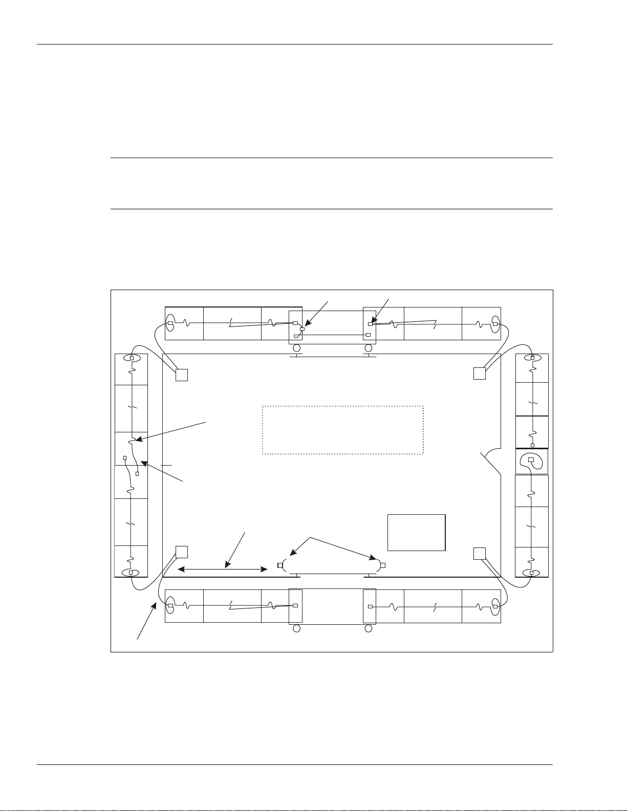
Figure 4: Sample site plan
gate disconnect terminator (typical)
sally port gate
(included in Z6) proc #2
swinging gate
(included in Z3)
NOTE:
proc #1
proc #4
proc #3
service
loops
end of zone overlap
(approx. 1.5 m, 5 ft.)
also required at start points
app. max. 270 m (886 ft.) microwave sensor main
building
gate disconnect
not required
- drip loops at each splice/termination
- service loops
- sensitivity loops at corner posts
sally port
gate
Z1 Z2
Z3
Z4
Z5
Z6
Z7
Z8
Z9
lead-in cable (typical)

Perimeter layout guidelines
FlexPS Product Guide Page 13
Perimeter layout guidelines
Use a site plan to mark the locations for the FlexPS components:
• Sensor cable - indicate the cable layout for each zone.
• Lead-in cable - Indicate the layout if lead-in cable is being used (at the processor, for a
bypass).
• Cable connectors - indicate the type of connection (splice, terminator).
• FlexPS processors (note the addresses for network based processors).
• Power supply - indicate the type of power supply and the power distribution plan.
• Alarm communication wiring (relay output or network alarm communications).
Sensor cable selection rules
There are two types of sensor cable available for use with the FlexPS system, MEX cable and
Mark 2 cable. MEX cable uses a fixed center conductor and contains a permanent electrical
charge. Mark 2 cable uses a loose center conductor inside a clear tube and generates an electrical
signal through the triboelectric effect.
Figure 5: Mark 2 and MEX sensor cable reels
150 m (492 ft.) reel
Mark 2 sensor cable
300 m (984 ft.) reel
MEX sensor cable

Perimeter layout guidelines
Page 14 FlexPS Product Guide
Use MEX sensor cable on standard chain-link, weldmesh and expanded metal fences. MEX
cable is thinner and lighter than Mark 2 sensor cable and does not require conditioning. MEX
sensor cable comes in 100 m (328 ft.) 200 m (656 ft.) and 300 m (984 ft.) lengths.
Use Mark 2 sensor cable on vinyl coated chain-link fences, on palisade fences, and on fences
that are used around sites with a high level of EMI such as electrical and solar power generating
stations. Mark 2 sensor cable has a higher sensitivity than MEX sensor cable, and requires cable
conditioning before it can be installed. Mark 2 sensor cable comes in 150 m (492 ft.) lengths. Two
lengths of Mark 2 can be spliced together to provide a 300 m (984 ft.) sensor cable.
Cable layout guidelines
• The sensor cable must be mounted on the same or similar type of surface for each zone.
• The maximum length of sensor cable is 300 meters (984 ft.) per zone.
• The smallest allowable bend radius for MEX sensor cable is 4 cm (1.6 in.).
• The smallest allowable bend radius for Mark 2 sensor cable is 7.5 cm (3 in.).
• The smallest allowable bend radius for Armour-FLEX sensor cable is 15 cm (6 in.).
• The sensor cable should follow the ground contour to maintain a constant height above the
ground.
Figure 6: MEX and Mark 2 cable comparison
Note Contact Senstar Customer Service for applications advice when
ordering FlexPS sensor cable.
Mark 2 cable
polyethylene
jacket
braided
shield loose solid
center conductor
clear tube
foil
clear tube
center conductor
aluminum foil
braided shield
outer black jacket
center conductor
braided shield
outer black jacket
MEX cable
polyethylene
jacket braided
shield fixed stranded
center conductor
dielectric core
MEX cable
Mark 2 cable
fixed center
conductor
loose center
conductor
dielectric core

Perimeter layout guidelines
FlexPS Product Guide Page 15
Cable length calculator
Typically, a zone requires approximately 10% more cable than the linear zone length. The
following table provides a guideline for calculating the amount of sensor cable required for a zone
(in meters):
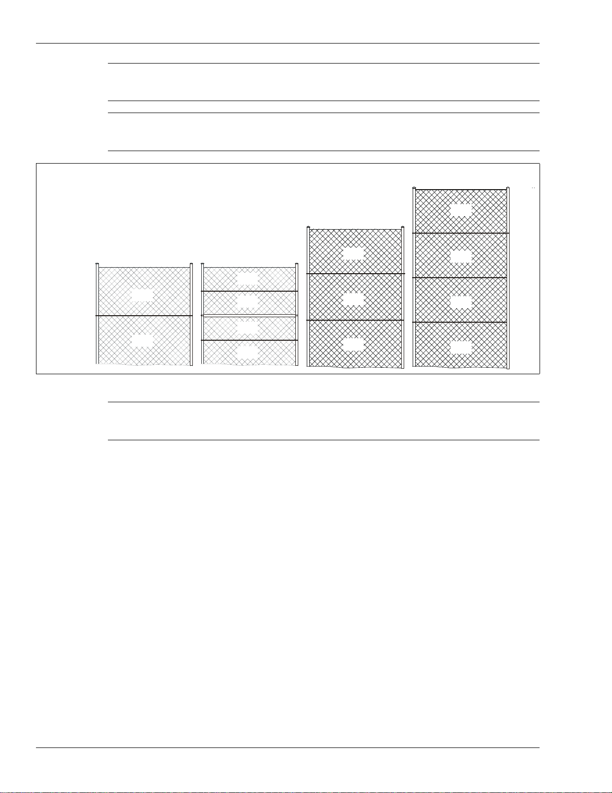
Fence height recommendations
The following cable spacing recommendations provide good security on well maintained fences.
However, depending on the security requirements and the fence condition, it is possible to use
alternate cable spacing. For example, on a high quality fence, in excellent condition, you could use
a single pass of cable to cover a 3 m (10 ft.) fence. However, to ensure the highest Pd, Senstar
recommends the following cable spacing (see Figure 7: ):
• For standard fences up to 2.5 meters (8 ft.) tall - a single pass of MEX sensor cable at 1/2 the
fence height.
• For standard fences greater than 2.5 m and less than 4.5 m (15 ft.) tall - a double pass of MEX
sensor cable at 1/3 and 2/3 the fence height.
• For standard fences exceeding 4.5 m - three or more equally spaced passes of MEX sensor
cable. This depends on the fence fabric and structure, and on the site’s security requirements.
• For vinyl coated fences up to 2.5 meters (8 ft.) tall - a double pass of Mark 2 sensor cable at
1/3 and 2/3 the fence height.
For higher vinyl coated fences, use double the recommended cable passes of Mark 2 cable for
standard chain-link of similar height.
• For palisade fences that are less than 1.8 m (6 ft.) high, a single pass of Mark 2 cable along
the top rail.
• For palisade fences that are greater than 1.8 m (6 ft.) high, use a dual pass of Mark 2 cable
along the top and middle rails.
Note Senstar strongly recommends installing the sensor cables on the
secure side of the perimeter (the side of the fence opposite the
threat).
zone element required cable length
start point + 1 m
service loops + 0.75 m X (linear zone length / 15)
corner and heavy gauge posts + 3.5 m X number of posts
cable terminations and splices + 0.5 m each
linear zone length + _ _ _ _ _ (zone length in meters)
required length of cable per pass = _ _ _ _ _ (total length in meters)
total length X number of passes = _ _ _ _ _ cable length (max. 300 m)
Note The term standard refers to uncoated chain link, weld mesh, and
expanded metal fences. Painted fences are included in the standard
fence type, but the fence must be painted before the sensor cable is
attached. If a fence will be painted after the sensor cable is installed, the
cable must be removed while the fence is being painted, and then
reinstalled after the paint has completely dried.
Perimeter layout guidelines
Page 16 FlexPS Product Guide
Fence corners and heavier gauge posts
Corner posts and heavier gauge support posts tend to dampen the fence’s vibration transmission
characteristics. Therefore, use cable loops at corner posts and heavy gauge support posts, to
increase the sensitivity. Each sensitivity loop requires approximately 3.5 m (11.5 ft.) of sensor
cable.
Service loops
Service loops provide extra sensor cable along the fence to make cable repairs. Allot 75 cm
(30 in.) of cable each 15 m (50 ft.) for a service loop. Locate the U-shaped service loops at fence
posts.
Drip loops
Drip loops raise the connector above the sensor cable to prevent water from running along the
cable and accumulating in the enclosure. Drip loops also relieve strain resulting from temperature
changes that cause the cable to expand and contract. Form the drip loop by raising the connector
15 cm (6 in.) above the level of the cable run. Allot 50 cm (20 in.) of cable for each splice or
termination.
Note If the lower edge of the fence fabric is embedded in a concrete
footing, or below ground, use an additional cable pass on the lower
section of fence to increase the sensitivity.
Note If the fence framework includes an intermediate (middle) rail, then
there must be at least one cable pass above the rail and one cable
pass below the rail.
Figure 7: Cable pass recommendations
Note Fences that use vinyl privacy slats may not be suitable for use with
a FlexPS sensor system, as the privacy slats have a tendency to
dampen vibrations.
h > 4.5 m (> 15 ft.)
h = 2.5 to 4.5 m (8 to 15 ft.)
h = 2.5 m (8 ft.)
1/2 h
1/2 h
1/3 h
1/3 h
1/3 h
1/4 h
1/4 h
1/4 h
1/4 h
sensor cable
and vinyl coated fences
single pass
double pass
triple pass
1/4 h
1/4 h
1/4 h
1/4 h
double pass (minimum)
fences with a middle rail

Perimeter layout guidelines
FlexPS Product Guide Page 17
Non-sensitive lead-in cable (MEX sensor cable)
Non-sensitive lead-in cable is almost identical to MEX sensor cable, but does not detect vibrations.
Lead-in cable is available in lengths of 30 m (98 ft.), 150 m (492 ft.) and 300 m (984 ft.). It allows
you to install the processor away from the start of the sensor zone, and is also used to bypass
gates, buildings, and other structures (see Figure 10: ). The recommended maximum length of
lead-in cable for a zone with 300 m of sensor cable is 150 m (492 ft.). This length can be extended
for zones that use shorter lengths of sensor cable (e.g., a zone with 200 m of sensor cable can use
up to 250 m of lead-in cable).
Non-sensitive lead-in cable (Mark 2 sensor cable)
For Mark 2 sensor cable, standard coaxial cable is used for lead-in cable and bypasses. The
length of non-detecting cable that can be used with Mark 2 is determined by the coaxial cable’s
capacitance. The following table includes the approved coaxial cable types that may be used as
lead-in cable with Mark 2 sensor cable, and the maximum lead-in lengths.
The maximum length of non-sensitive cable is based on a zone with 300 m of Mark 2 sensor
cable. The length of non-detecting cable may be extended, provided the length of the Mark 2
sensor cable is reduced accordingly.
Gate bypass
If there is a gate within a FlexPS sensor zone, you require a sufficient amount of lead-in cable to
bypass the gate, even if the gate is protected by sensor cable. Bury the bypass cable in PVC
conduit. See Figure 36: for an example of a bypassed gate, which uses a microwave system to
provide security across the gate.
Gate bypass modules
The gate bypass module is used to bypass a protected gate without triggering an intrusion alarm.
Refer to instruction sheet G5DA0103 for detailed installation instructions for the gate bypass
modules. See Figure 8: and Figure 9: for illustrations of gate bypass modules.
Non-sensitive cable type Maximum length
RG-59/U, 69 pf/m (21 pf/ft.) 116 m (380 ft.)
RG-62/U, 43 pf/m (13 pf/ft.) 186 m (610 ft.)

Perimeter layout guidelines
Page 18 FlexPS Product Guide
There are two types of gate bypass modules available:
• Local bypass module for manual activation (key switch)
When the key is in the access position:
The sensor cable is shunted around the gate or terminated at the gate, depending on the
configuration.
The status contacts close giving a signal to the annunciator device.
Removing the faceplate opens the tamper switch.
• Remote bypass module for remote activation
Remote operation from the display and control system requires a voltage input to the gate
bypass module to energize the bypass relay.
When the relay is energized, the sensor cable is either shunted around the gate or terminated
at the gate, and the bypass module’s status contacts close to signal the annunciator.
If the cover is removed from the bypass housing, the tamper switch opens to signal the
annunciator.
Figure 8: Gate bypass module example
Figure 9: Gate bypass modules
gate bypass module
gate bypassed
splice kit
gate protected
bypass cable
MODEL 2490-2
SECURE ACCESS
MODEL 2490-1
local gate bypass module remote gate bypass module
Perimeter layout guidelines
FlexPS Product Guide Page 19
Armour-FLEX
Armour-FLEX is FlexPS sensor cable encased in a flexible metallic conduit. There are two types of
Armour-FLEX cable, MEX and Mark 2. Armour-FLEX protects the sensor cable from damage and
vandalism, as well as from the sun and weather. Steel cable ties or wire ties are the recommended
fasteners for Armour-FLEX, although UV resistant cable ties can also be used. Armour-FLEX is
available in lengths of 100 meters (328 ft.). Up to three lengths can be spliced together to create a
300 meter (984 ft.) cable. Armour-FLEX splices must be enclosed inside outdoor rated electrical
junction boxes (condulets). Refer to the Sensor cable selection rules on page 13 to select the
correct type of Armour-FLEX cable for your application.
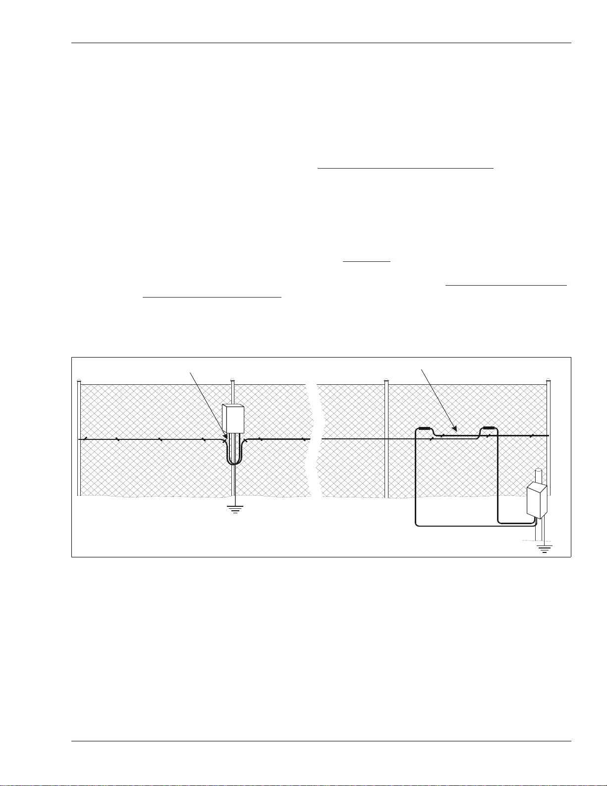
Processor location guidelines
The FlexPS processor can be mounted outdoors on a post, either on, or separate from, the fence
on which the sensor cables are installed (see Figure 10: ). A rigid fixed post is recommended for
outdoor applications. The maximum distance away from the fence that the processor can be
installed is determined by the non-sensitive lead-in cable length (see Non-sensitive lead-in cable
(MEX sensor cable) on page 17). The FlexPS processor can also be installed indoors or outdoors
on a flat stable surface. A post-mount kit is available for post sizes from 4.5 cm to 12.7 cm (1.75 in.
to 5 in.). The hardware required for mounting the processor on a flat surface is customer-supplied.
For installations in which the enclosure must be locked, there is a lockable mounting kit available.
The lockable kit can be used to post-mount or surface mount the FlexPS enclosure.
AC/DC Power source and wiring
The FlexPS processor operates on a wide range of input voltages (12 to 48 VDC). The power
supply, the number of processors, and the lengths of the power cable runs will determine the
gauge of the power cable wiring. In locations where AC power may not be stable or reliable, an
uninterruptable power supply (UPS) should be used for primary power. The following tables
include power cable/load recommendations for 24 VDC and 48 VDC power supplies. The table
assumes a maximum power consumption of 2 W per processor (with NIC and backup battery).
Figure 10: Processor location/ start point overlaps
service loop overlap for fence-mounted processor
lead-in cable
earth ground
1.5 m overlap for post-mounted processor
(consult the local electrical code for grounding requirements) earth ground

Perimeter layout guidelines
Page 20 FlexPS Product Guide
Power over Ethernet
Silver Network based processors using Ethernet communications have the option of using Power
over Ethernet technology to power the FlexPS processor. To use this powering option requires a
PoE standard class 3 switch that is located a maximum of 100 m (328 ft.) from the processor, and
Category 5 network cable. Power over Ethernet is supplied to the processor’s Network Interface
card (NIC) and the power output on the NIC is connected to the power input on the processor.
zone length processor
separation wire gauge power supply
output voltage number of
processors power supply
connected to
processor #
300 m (984 ft.) 600 m (1968 ft.) 18 AWG
(1.02 - 1.27 mm) 24 VDC 5 3
48 VDC 9 5
250 m (820 ft.) 500 m (1640 ft.) 18 AWG
(1.02 - 1.27 mm) 24 VDC 5 3
48 VDC 11 6
200 m (656 ft.) 400 m (1312 ft.) 18 AWG
(1.02 - 1.27 mm) 24 VDC 5 3
48 VDC 11 6
150 m (492 ft.) 300 m (984 ft.) 18 AWG
(1.02 - 1.27 mm) 24 VDC 7 4
48 VDC 13 7
100 m (328 ft.) 200 m (656 ft.) 18 AWG
(1.02 - 1.27 mm) 24 VDC 7 4
48 VDC 17 9
50 m (164 ft.) 100 m (328 ft.) 18 AWG
(1.02 - 1.27 mm) 24 VDC 11 6
48 VDC 25 13
Table 1 Power supply/power cable loads (18 AWG power cable)
zone length processor
separation wire gauge power supply
output voltage number of
processors power supply
connected to
processor #
300 m (984 ft.) 600 m (1968 ft.) 16 AWG
(1.29 - 1.53 mm) 24 VDC 5 3
48 VDC 13 7
250 m (820 ft.) 500 m (1640 ft.) 16 AWG
(1.29 - 1.53 mm) 24 VDC 7 4
48 VDC 13 7
200 m (656 ft.) 400 m (1312 ft.) 16 AWG
(1.29 - 1.53 mm) 24 VDC 7 4
48 VDC 15 8
150 m (492 ft.) 300 m (984 ft.) 16 AWG
(1.29 - 1.53 mm) 24 VDC 9 5
48 VDC 15 8
100 m (328 ft.) 200 m (656 ft.) 16 AWG
(1.29 - 1.53 mm) 24 VDC 11 6
48 VDC 21 11
50 m (164 ft.) 100 m (328 ft.) 16 AWG
(1.29 - 1.53 mm) 24 VDC 15 8
48 VDC 31 16
Table 2 Power supply/power cable loads (16 AWG power cable)
CAUTION The PoE NIC is intended to supply power only to the processor on
which it is mounted. Do not attempt to power an auxiliary device with
the PoE NIC.
Note Senstar strongly recommends the use of a fully managed PoE switch to
connect and power IP based FlexPS processors.
Table of contents
Other SENSTAR Accessories manuals

SENSTAR
SENSTAR FPS 2-2 User manual

SENSTAR
SENSTAR FlexZone WGS User manual

SENSTAR
SENSTAR FiberPatrol FP1150 Series User manual

SENSTAR
SENSTAR UltraWave BR100 User manual

SENSTAR
SENSTAR OmniTrax User manual

SENSTAR
SENSTAR FlexZone User manual

SENSTAR
SENSTAR IntelliFIBER User manual

SENSTAR
SENSTAR FiberPatrol FP1100X Series Technical manual

SENSTAR
SENSTAR FiberPatrol FP400 User manual


