SENSTAR FiberPatrol FP1100X Series Technical manual

Site Planning
Guide
FiberPatrol®
Ranging Fiber Optic Fence Protection Sensor
FPDA0102-401, Rev F
January 8, 2019
& Installation
FP1100X/FP1400 series

Page 2 FiberPatrol Site Planning & Installation Guide
FiberPatrol
FPDA0102-401, Rev F
January 8, 2019
Website: www.senstar.com
FiberPatrol, Senstar and the Senstar logo are registered trademarks, and Silver Network is a trademark of Senstar Corporation.
Product names and Company names included in this document are used only for identification purposes and are the property
of, and may be trademarks of, their respective owners. Copyright © 2016, Senstar Corporation, all rights reserved. Printed in
Canada.
The information provided in this guide has been prepared by Senstar Corporation to the best of its ability. Senstar Corporation is
not responsible for any damage or accidents that may occur due to errors or omissions in this guide. Senstar Corporation is not
liable for any damages, or incidental consequences, arising from the use of, or the inability to use, the software and equipment
described in this guide. Senstar Corporation is not responsible for any damage or accidents that may occur due to information
about items of equipment or components manufactured by other companies. Features and specifications are subject to change
without notice.
The figures included in this document are for illustration purposes only, and may differ from the actual equipment.
Compliance
The use of shielded cables is required for compliance.
Canada: This Class A digital apparatus meets all requirements of the Canadian Interference-Causing Equipment Regulations.
Cet appareil numérique de la classe A respecte toutes les exigences du Règlement sur le matériel brouilleur du Canada.
USA: This device complies with part 15 of the FCC Rules. Operation is subject to the following two conditions: (1) This device
may not cause harmful interference, and (2) this device must accept any interference received, including any interference that
may cause undesired operation.
Note: This equipment has been tested and found to comply with the limits for a Class A digital device, pursuant to part 15 of the
FCC Rules. These limits are designed to provide reasonable protection against harmful interference when the equipment is
operated in a commercial environment. This equipment generates, uses and can radiate radio frequency energy and, if not
installed and used in accordance with the instruction manual, may cause harmful interference to radio communications.
Operation of this equipment in a residential area is likely to cause harmful interference in which case the user will be required to
correct the interference at his own expense.
Any changes or modifications to the software or equipment that are not expressly approved by Senstar Corporation void the
manufacturer’s warranty, and could void the user’s authority to operate the equipment.
Europe: This device conforms to EC low voltage directive 2006/95/EC.
Senstar Corporation’s Quality Management System is ISO 9001:2015 registered.
Service statement - We ensure that our products are correctly applied to achieve the maximum benefits for the end-user. We
work hand-in-hand with our customers and remain accessible through all stages of a project - from concept to deployment to
long-term support. We provide design assistance, site surveys, installation support, comprehensive documentation, training,
post-installation annual calibration and maintenance visits, electronics and software extended warranty, rapid factory repair
service and on-call/emergency service.

FiberPatrol Site Planning & Installation Guide Page 3
Table of contents
1 System description - - - - - - - - - - - - - - - - - - - - - - - - - - - - - - - - - - - - - - - -5
Principles of operation - - - - - - - - - - - - - - - - - - - - - - - - - - - - - - - - - - - - - - - - - - - - - - 5
FiberPatrol sensor system details - - - - - - - - - - - - - - - - - - - - - - - - - - - - - - - - - - - - - - 5
FP1100X configurations - - - - - - - - - - - - - - - - - - - - - - - - - - - - - - - - - - - - - - - - - - - - - - - - - - 6
Alarm reporting - - - - - - - - - - - - - - - - - - - - - - - - - - - - - - - - - - - - - - - - - - - - - - - - - - - - - - - -7
FP1100X Series Cable length requirements - - - - - - - - - - - - - - - - - - - - - - - - - - - - - - - - - - - 7
FP1400 sensors - - - - - - - - - - - - - - - - - - - - - - - - - - - - - - - - - - - - - - - - - - - - - - - - - - - - - - - 8
FiberPatrol components - - - - - - - - - - - - - - - - - - - - - - - - - - - - - - - - - - - - - - - - - - - 9
Processor - - - - - - - - - - - - - - - - - - - - - - - - - - - - - - - - - - - - - - - - - - - - - - - - - - - - - - - 9
Controller - - - - - - - - - - - - - - - - - - - - - - - - - - - - - - - - - - - - - - - - - - - - - - - - - - - - - - 10
Start module/fiber patch panel - - - - - - - - - - - - - - - - - - - - - - - - - - - - - - - - - - - - - - - - 10
Outdoor splice enclosure - - - - - - - - - - - - - - - - - - - - - - - - - - - - - - - - - - - - - - - - - - - 10
End module - - - - - - - - - - - - - - - - - - - - - - - - - - - - - - - - - - - - - - - - - - - - - - - - - - - - - 11
Sensor cable/non-detecting lead cable - - - - - - - - - - - - - - - - - - - - - - - - - - - - - - - - - - 11
Cable ties - - - - - - - - - - - - - - - - - - - - - - - - - - - - - - - - - - - - - - - - - - - - - - - - - - - - - - 12
Isolation loops - - - - - - - - - - - - - - - - - - - - - - - - - - - - - - - - - - - - - - - - - - - - - - - - - - - 12
Buried vault - - - - - - - - - - - - - - - - - - - - - - - - - - - - - - - - - - - - - - - - - - - - - - - - - - - - - - - - - 12
2 Site planning - - - - - - - - - - - - - - - - - - - - - - - - - - - - - - - - - - - - - - - - - - - - 13
FiberPatrol configurations - - - - - - - - - - - - - - - - - - - - - - - - - - - - - - - - - - - - - - - - 13
Loop configurations - - - - - - - - - - - - - - - - - - - - - - - - - - - - - - - - - - - - - - - - - - - - - - - 13
Open-ended loop configuration - - - - - - - - - - - - - - - - - - - - - - - - - - - - - - - - - - - - - - - - - - - - 14
Split configuration - - - - - - - - - - - - - - - - - - - - - - - - - - - - - - - - - - - - - - - - - - - - - - - - - 16
Line configurations - - - - - - - - - - - - - - - - - - - - - - - - - - - - - - - - - - - - - - - - - - - - - - - - 17
Extended lead configuration - - - - - - - - - - - - - - - - - - - - - - - - - - - - - - - - - - - - - - - - - - - - - - 18
Site survey - - - - - - - - - - - - - - - - - - - - - - - - - - - - - - - - - - - - - - - - - - - - - - - - - - - 19
Fences - - - - - - - - - - - - - - - - - - - - - - - - - - - - - - - - - - - - - - - - - - - - - - - - - - - - - - - - 19
Chain-link fences - - - - - - - - - - - - - - - - - - - - - - - - - - - - - - - - - - - - - - - - - - - - - - - - - - - - - 19
Weld-mesh fences - - - - - - - - - - - - - - - - - - - - - - - - - - - - - - - - - - - - - - - - - - - - - - - - - - - - 19
Fence height considerations - - - - - - - - - - - - - - - - - - - - - - - - - - - - - - - - - - - - - - - - - 20
Climb-over deterrent hardware - - - - - - - - - - - - - - - - - - - - - - - - - - - - - - - - - - - - - - - 20
Barbed wire - - - - - - - - - - - - - - - - - - - - - - - - - - - - - - - - - - - - - - - - - - - - - - - - - - - - - - - - - 20
Razor ribbon/concertina - - - - - - - - - - - - - - - - - - - - - - - - - - - - - - - - - - - - - - - - - - - - - - - - - 21
Gates - - - - - - - - - - - - - - - - - - - - - - - - - - - - - - - - - - - - - - - - - - - - - - - - - - - - - - - - - 22
Gate bypasses - - - - - - - - - - - - - - - - - - - - - - - - - - - - - - - - - - - - - - - - - - - - - - - - - - - - - - - 22

Page 4 FiberPatrol Site Planning & Installation Guide
Protecting swinging gates with FiberPatrol - - - - - - - - - - - - - - - - - - - - - - - - - - - - - - - - - - - 22
Gate protection for periodically bypassed gates (independent zones) - - - - - - - - - - - - - - - - 23
Determining cable length requirements for gates - - - - - - - - - - - - - - - - - - - - - - - - - - - - - - - 24
Using the cable management kit at the hinged side of protected swinging gates - - - - - - - - 24
Protecting masonry walls and buildings - - - - - - - - - - - - - - - - - - - - - - - - - - - - - - - - - -25
Selecting conduit for below ground bypasses - - - - - - - - - - - - - - - - - - - - - - - - - - - - - -26
Solid wall conduit - - - - - - - - - - - - - - - - - - - - - - - - - - - - - - - - - - - - - - - - - - - - - - - - - - - - - 27
Split wall conduit - - - - - - - - - - - - - - - - - - - - - - - - - - - - - - - - - - - - - - - - - - - - - - - - - - - - - 27
Sensitivity loops for heavy gauge posts and corner posts - - - - - - - - - - - - - - - - - - - - - -27
Service loops - - - - - - - - - - - - - - - - - - - - - - - - - - - - - - - - - - - - - - - - - - - - - - - - - - - - - - - - 28
Isolation loops - - - - - - - - - - - - - - - - - - - - - - - - - - - - - - - - - - - - - - - - - - - - - - - - - - - - - - - 29
Cable bypasses for buildings and structures - - - - - - - - - - - - - - - - - - - - - - - - - - - - - - - - - - 29
Deploying the sensor cable - - - - - - - - - - - - - - - - - - - - - - - - - - - - - - - - - - - - - - - - - - -31
Sensor cable splices - - - - - - - - - - - - - - - - - - - - - - - - - - - - - - - - - - - - - - - - - - - - - - -31
Site analysis checklist - - - - - - - - - - - - - - - - - - - - - - - - - - - - - - - - - - - - - - - - - - - - - - -32
Cable requirements - - - - - - - - - - - - - - - - - - - - - - - - - - - - - - - - - - - - - - - - - - - - - - - -33
Equipment requirements - - - - - - - - - - - - - - - - - - - - - - - - - - - - - - - - - - - - - - - - - - - - -33
3 Installing FiberPatrol - - - - - - - - - - - - - - - - - - - - - - - - - - - - - - - - - - - - - - 35
FiberPatrol installation overview - - - - - - - - - - - - - - - - - - - - - - - - - - - - - - - - - - - - - - -35
Laser light safety - - - - - - - - - - - - - - - - - - - - - - - - - - - - - - - - - - - - - - - - - - - - - - - - - -35
Optical fiber safety - - - - - - - - - - - - - - - - - - - - - - - - - - - - - - - - - - - - - - - - - - - - - - - - -36
Fiber optic cable handling - - - - - - - - - - - - - - - - - - - - - - - - - - - - - - - - - - - - - - - - - - - -36
FiberPatrol sensor cable performance specifications - - - - - - - - - - - - - - - - - - - - - - - - - - - - 36
Additional cable requirements - - - - - - - - - - - - - - - - - - - - - - - - - - - - - - - - - - - - - - - - - - - - 36
Cable loss limits (maximum attenuation) - - - - - - - - - - - - - - - - - - - - - - - - - - - - - - - - - - - - - 37
Cable handling recommendations - - - - - - - - - - - - - - - - - - - - - - - - - - - - - - - - - - - - - - - - - 37
Illustrated installation requirements - - - - - - - - - - - - - - - - - - - - - - - - - - - - - - - - - - - - - - - - 37
FiberPatrol sensor cable and below ground bypasses - - - - - - - - - - - - - - - - - - - - - - - - - - - 41
FiberPatrol installation - - - - - - - - - - - - - - - - - - - - - - - - - - - - - - - - - - - - - - - - - - -42
Attaching the sensor cable - - - - - - - - - - - - - - - - - - - - - - - - - - - - - - - - - - - - - - - - - - -43
Attaching the sensor cable at protected swinging gates - - - - - - - - - - - - - - - - - - - - - - - - - - 43
Masonry walls and buildings - - - - - - - - - - - - - - - - - - - - - - - - - - - - - - - - - - - - - - - - - -44
Control equipment installation - - - - - - - - - - - - - - - - - - - - - - - - - - - - - - - - - - - - - -46
FiberPatrol splices - - - - - - - - - - - - - - - - - - - - - - - - - - - - - - - - - - - - - - - - - - - - - - - - -48
4 Maintenance - - - - - - - - - - - - - - - - - - - - - - - - - - - - - - - - - - - - - - - - - - - - 51
Recommended maintenance - - - - - - - - - - - - - - - - - - - - - - - - - - - - - - - - - - - - - -51
a System component list - - - - - - - - - - - - - - - - - - - - - - - - -53
b Specifications - - - - - - - - - - - - - - - - - - - - - - - - - - - - - -55
c Location/calibration table - - - - - - - - - - - - - - - - - - - - - - - -59

FiberPatrol Site Planning & Installation Guide Page 5
1 System description
Principles of operation
The FiberPatrol fence-mounted perimeter intrusion detection sensor system, detects and locates
intruders using fiber optic technology. FiberPatrol senses and locates minute vibrations in the
fence fabric caused by climbing, cutting, lifting, or otherwise disturbing the fence fabric. A fiber
optic sensor cable is attached to a perimeter fence. The controller unit transmits a laser light into
two single-mode fibers in the sensor cable. The controller picks up the back-scatter reflections
caused by fence motion or vibrations in the fence fabric and sends the data to the processor unit.
The processor determines the magnitude and location of the disturbance, and triggers an alarm
when the disturbance meets the criteria for a valid intrusion.
The sensor cable is a communication-grade single-mode fiber optic cable intended for outdoor
installation. The cable includes two dedicated sensing fibers. Depending on the particular fiber
optic cable used, at least 10 dark fibers are available for other perimeter applications (e.g., CCTV,
data communication, etc.). The sensor cable is generally available in lengths up to 12 km (7.5 mi.)
and requires professional installation using telecom industry standard practices. All fiber splices
require fusion splicing, and the sensor unit fiber optic connections use FC/APC type connectors.
FiberPatrol can operate as a standalone sensor, which communicates alarm conditions via
optional relay output modules. A PC-based security management system, such as the Alarm
Integration Module, or StarNeT, can serve as the primary operator interface for a FiberPatrol
system. FiberPatrol can also report alarms to 3rd party security management systems (SMS) via
the Network Manager Service. The security management system monitors the FiberPatrol sensor,
and can report alarms to an operator on a graphical site-map.
The FiberPatrol system includes Windows-based configuration software, which is used to setup
and calibrate the system. The configuration software enables sensor calibration, detection
parameter adjustments and system configuration settings.
FiberPatrol sensor system details
• passive, fiber optic, fence mounted outdoor perimeter intrusion detection system
• uses standard outdoor rated telecommunication grade single-mode fiber optic cables
• additional dark fibers available for auxiliary perimeter device communications
• models available for single pass coverage for fences up to 3 m (10 ft.) high
• no power required for outdoor components
• outdoor components unaffected by lightning, EMI, or electrical transients
Page 6 FiberPatrol Site Planning & Installation Guide
• outdoor rated splice enclosures for fiber termination and access to fibers
• indoor components are rack-mountable in a standard EIA 19 in. equipment rack:
• processor - locates disturbance, triggers alarms, monitors system status, includes
FiberPatrol system software, configuration software and Network Manager software
• controller - transmits laser light into two dedicated fibers and receives and isolates back-
scatter signals, analyzes received signal, passes information to processor for analysis
• start module - 1RU splice tray for connecting non-detecting lead cable to patch cables in
the equipment room, separates the backscatter reflections from the transmitted laser light,
and passes the backscatter to the controller unit
• LCD keyboard/monitor/mouse combo - 1 RU user interface provides control,
maintenance, calibration and configuration access to the FiberPatrol processor
FP1100X configurations
There are three distinct configurations for the FP1100X series sensor:
• Loop configurations in which the two sensors run in opposite directions in the fiber optic cable.
• Split configurations in which the two sensors run in opposite directions, in two fiber optic
cables.
• Line configurations in which both sensors run in the same direction in the fiber optic cable.
The loop configuration provides single cable cut immunity whereby detection will continue over the
full length of the perimeter in the event of a single cut in the sensor cable. In the split configuration,
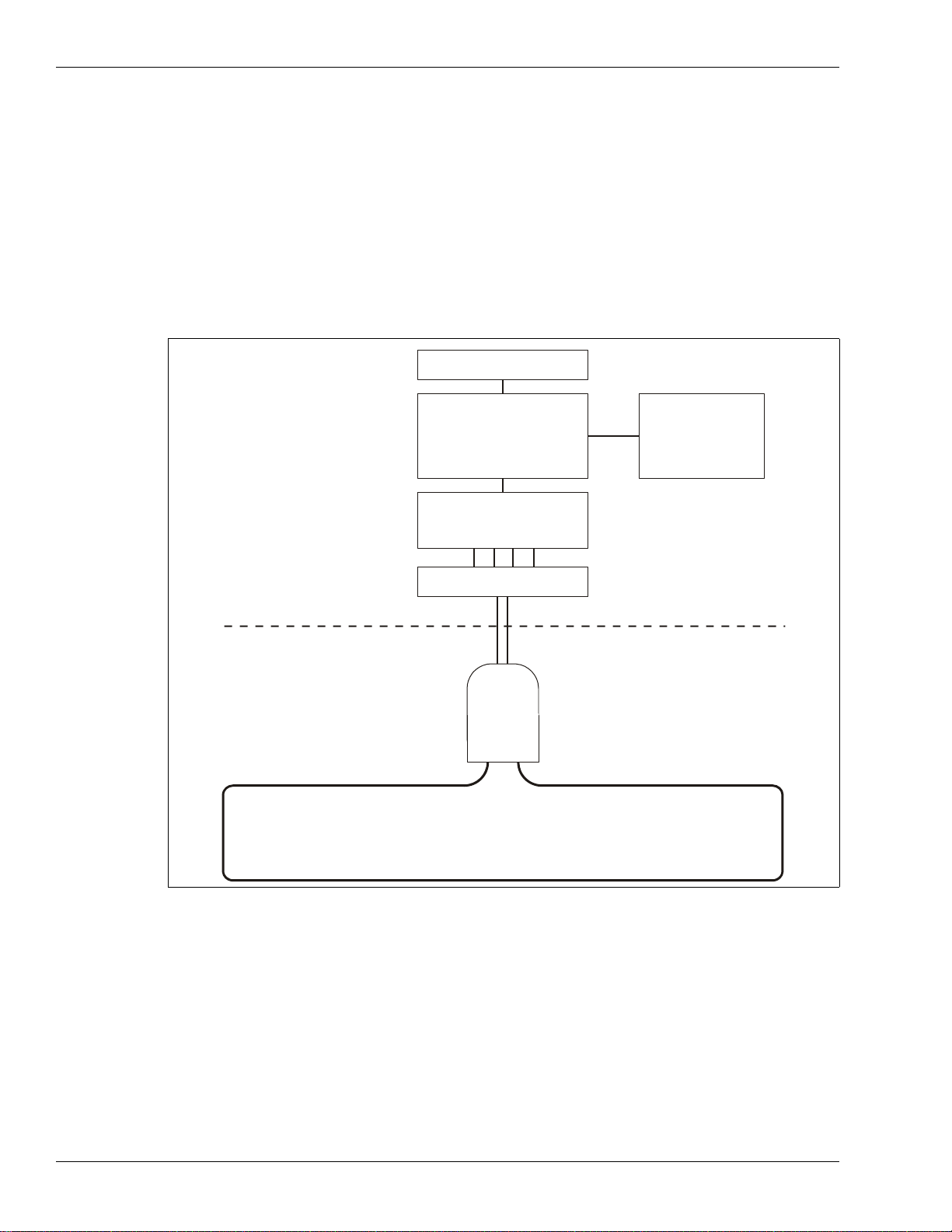
Figure 1: FiberPatrol block diagram - fully closed loop redundant configuration
splice
enclosure
with end
modules
fiber optic sensor cable
non-detecting lead cable
fiber optic
control room
perimeter
controller
start module
fiber optic patch panel
processor
keyboard/monitor/mouse
security
system
management

FiberPatrol Site Planning & Installation Guide Page 7
the two sensors work independently to provide twice the linear length of protection as compared to
the loop configuration. However, a cut cable ends detection beyond the point of the cut. In the line
configuration, the two sensors run in the same direction in the sensor cable and work in tandem for
alarm detection. With the line configuration, a cut cable ends detection beyond the point of the cut.
Alarm reporting
The FiberPatrol sensor can be incorporated into any system, which accepts contact closure alarm
data. However, contact closure alarm notification does not provide precise target location. A
contact closure based FP1100X Series system can be configured to report up to 262 distinct alarm
zones, plus system supervision and fail alarms through the UltraLink I/O system. A contact closure
based FP1400-08 system can be configured to report up to eight distinct alarm zones (up to 28
alarm zones via the optional add-on modules) plus system supervision and fail alarms through the
UltraLink I/O system. The FP1400-12 system can be configured to report up to twelve distinct
alarm zones (up to 44 alarm zones via the optional add-on modules) plus system supervision and
fail alarms.
The FiberPatrol sensor can communicate with third party security management systems through
the Network Manager Interface. In this case, the FiberPatrol security perimeter can be displayed
on a graphic site map as a series of alarm zones (e.g., when a sensor alarm occurs, the zone
flashes to identify the alarm’s location). Key features of a FiberPatrol system include:
• user-configurable alarm zone display
• fast response time (1 second or less)
• digital recording of alarm history
• FP1100X Series - up to 1440 software defined alarm zones (software defined alarm zones
enable the redistribution of alarm zones and zone lengths to accommodate changes in
security equipment and requirements)
• alarm location accuracy typically within 4 m (13 ft.) increases the overall efficiency of the
entire security system
• FP1400-08 - up to 8 software defined alarm zones (software defined alarm zones enable the
redistribution of alarm zones and zone lengths to accommodate changes in security
equipment and requirements)
• up to 28 software defined alarm zones via optional add-on modules
• FP1400-12 - up to 12 software defined alarm zones (software defined alarm zones enable the
redistribution of alarm zones and zone lengths to accommodate changes in security
equipment and requirements)
• up to 44 software defined alarm zones via optional add-on modules
FP1100X Series Cable length requirements
Note The distance reported by the FiberPatrol sensor unit is the optical
distance of the sensor fiber within the cable. This length is similar to a
measurement made by OTDR equipment. The optical distance can be
up to 3% greater than the cable length due to the Helix factor of the
fiber optic cable.
Note To ensure that there is enough sensor cable to cover the fence and
any installation variations, Senstar recommends ordering a 15%
overage (e.g., to protect 1 km of fence, order 1.15 km of sensor cable).

Page 8 FiberPatrol Site Planning & Installation Guide
The FiberPatrol FP1100X Series fence protection system is available in eight models, which are
based on the required length of fiber optic cable. Careful site planning is essential to ensure the
components that are ordered, are the correct components for the application. The following table
includes the FP1100X Series models that are available for fence-mounted applications:
FP1400 sensors
The FiberPatrol FP1400 Series fence protection system is available in two models:
The FiberPatrol FP1400-08 system provides up to 2.5 km (1.55 mi.) of combined fiber optic sensor
cable and non-detecting lead cable and reports alarm conditions in 8 independent alarm zones
(expandable to 28 alarm zones via the optional add-on modules).
The FiberPatrol FP1400-12 system provides up to 5 km (3.1 mi.) of combined fiber optic sensor
cable and non-detecting lead cable and reports alarm conditions in 12 independent alarm zones
(expandable to 44 alarm zones via the optional add-on modules).
Model number Description
FP1100X-01 • up to 1.5 km (0.93 mi.) of detection processing for cut-immune
configurations
• up to 3 km (1.86 mi.) of detection processing for non cut-immune
configurations
FP1100X-03 • up to 3 km (1.86 mi.) of detection processing for cut-immune
configurations
• up to 6 km (3.73 mi.) of detection processing for non cut-immune
configurations
FP1100X-06 • up to 6 km (3.73 mi.) of detection processing for cut-immune
configurations
• up to 12 km (7.46 mi.) of detection processing for non cut-immune
configurations
FP1100X-09 • up to 9 km (5.59 mi.) of detection processing for cut-immune
configurations
• up to 18 km (11.18 mi.) of detection processing for non cut-immune
configurations
FP1100X-12 • up to 12 km (7.46 mi.) of detection processing for cut-immune
configurations
• up to 24 km (14.91 mi.) of detection processing for non cut-immune
configurations
FP1100X-16 • up to 16 km (9.94 mi.) of detection processing for cut-immune
configurations
• up to 32 km (19.9 mi.) of detection processing for non cut-immune
configurations
FP1100X-20 • up to 20 km (12.43 mi.) of detection processing for cut-immune
configurations
• up to 40 km (24.85 mi.) of detection processing for non cut-immune
configurations
FP1100X-25 • up to 25 km (15.53 mi.) of detection processing for cut-immune
configurations
• up to 50 km (31.07 mi.) of detection processing for non cut-immune
configurations
FiberPatrol components
FiberPatrol Site Planning & Installation Guide Page 9
FiberPatrol components
Processor
The FiberPatrol processor supports two independent fiber optic sensors (S1, S2) and can monitor
up to 1440 distinct alarm zones. The alarm zones are defined in software, and do not depend on
cable length. The processor operates on 100 to 240 VAC, 50/60 Hz power and can annunicate
alarm conditions with contact closure outputs or via the Network Manager software. The processor
has dual redundant power supplies, which include an audible alert output that is activated in the
event that one of the power supplies fails. There is a pushbutton switch located between the two
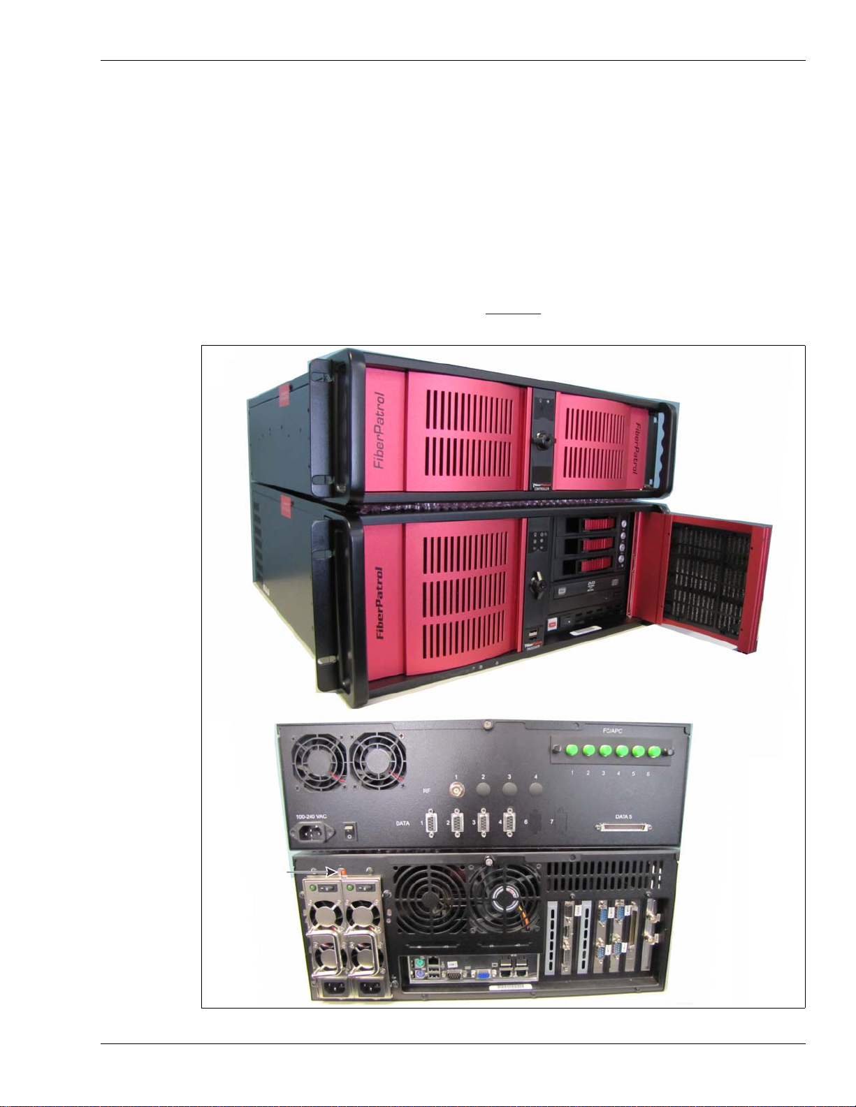
power supplies that will silence the alert tone. Figure 2: illustrates front and rear views of a
FiberPatrol processor and controller.
Figure 2: FiberPatrol processor
Front view
Rear view
power supply
processor
controller
processor
controller
alert tone
reset switch
FiberPatrol components
Page 10 FiberPatrol Site Planning & Installation Guide
Controller
The FiberPatrol controller (see Figure 2:) generates the laser light signal that is transmitted into the
fiber sensors. The controller collects the backscatter reflections created by vibrations in the
protected fence, analyzes the signal, and passes the data to the processor.
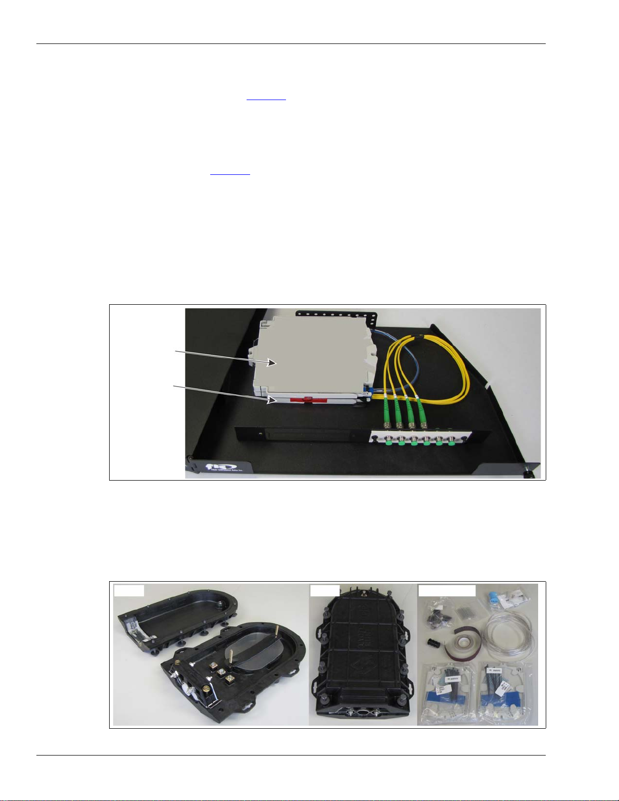
Start module/fiber patch panel
The start module (see Figure 3:) connects the non-detecting lead cable to the sensor unit in the
equipment room. The start module is housed in a 1 RU fiber patch panel along with a splice tray.
The two sensor fibers from the lead cable must be spliced to two fibers from the start module. Four
additional fibers from the start module are factory spliced to four fiber pigtails, which are attached
to FC/APC connectors on the outside of the of the enclosure. Fiber patch cables then connect the
four fibers to the FiberPatrol controller. The splice tray includes six unused protective sleeves,
which are available to provide access to the dark fibers in the lead/sensor cable. Optionally, a
second splice tray can be added to the enclosure, to make connections to any additional fibers
that are being used. In some configurations, an end module is incorporated into the start module
enclosure inside the rack mounted fiber patch panel. Refer to Chapter 2, Site planning for
additional details.
Outdoor splice enclosure
The outdoor splice enclosure houses all field splices for the FiberPatrol system. The splice
enclosure is also used to protect the FiberPatrol end module when it is installed outdoors. The
splice enclosure is generally mounted on the protected fence.
Figure 3: FiberPatrol start module/splice tray
Figure 4: FiberPatrol outdoor splice components
Rear view
splice tray
start module
open closed consumables
FiberPatrol components
FiberPatrol Site Planning & Installation Guide Page 11
End module
The end module terminates the laser light at the end of each detecting fiber, without causing
undesirable reflections. There are 3 types of end modules available, a single end module
(FPMA0212) a double end module (FPMA0222) and a combined double start/end module
(FPMA0223).The end module can be located outdoors in a splice enclosure or indoors with the
start module, in the fiber patch panel. The location of the end module depends on the sensor cable
configuration.
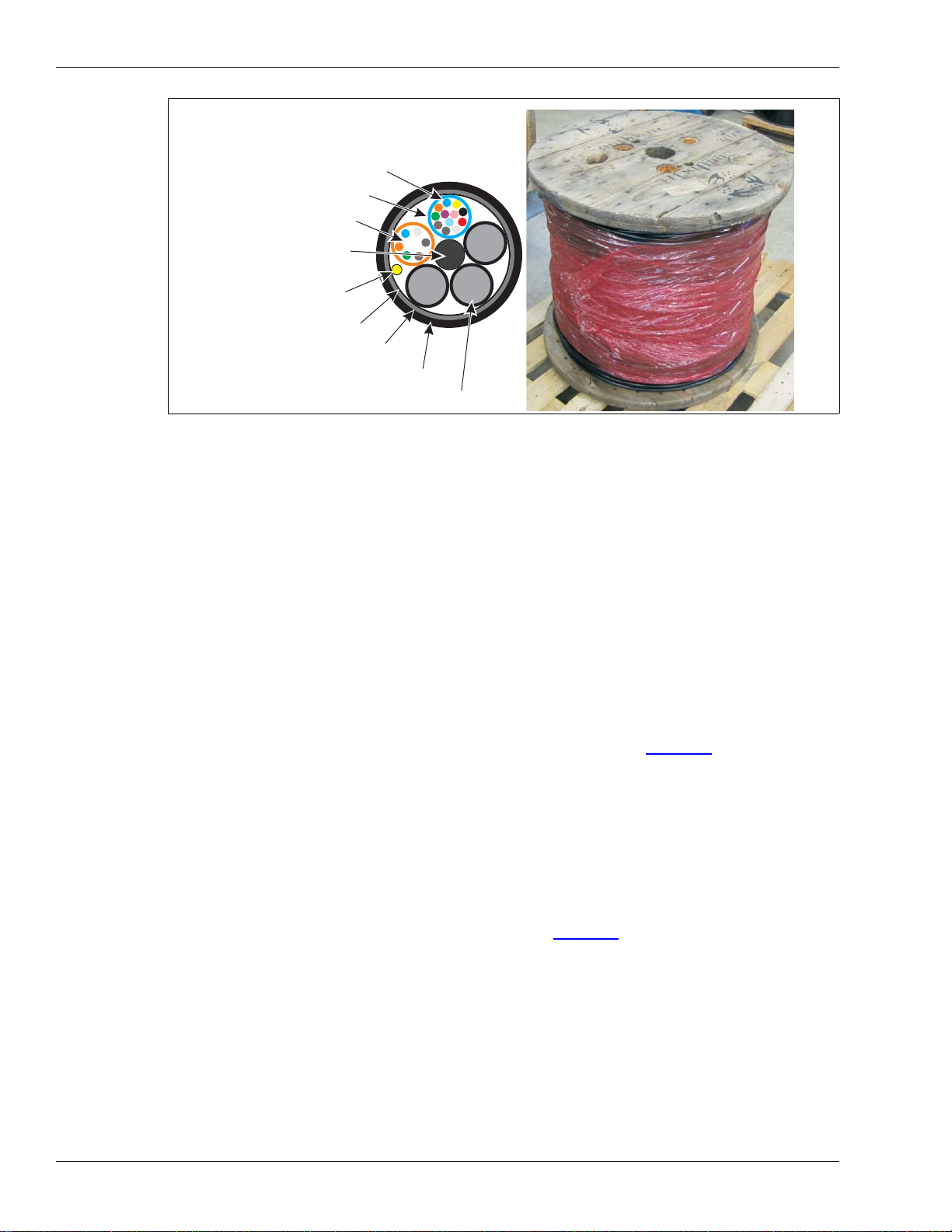
Sensor cable/non-detecting lead cable
FiberPatrol sensor cable is telecommunication grade single-mode fiber optic cable with a medium
density polyethylene outer jacket and a waterblock system. The non-armored loose tube cable is
comprised of a 5 unit fiber optic core (PE filler units and 12-fiber/6-fiber buffer tubes) a central
strength member and a rip cord. Sensor cable can be ordered in lengths to match application
requirements. The non-detecting lead cable is identical to the sensor cable, with detection
sensitivity being controlled via software.
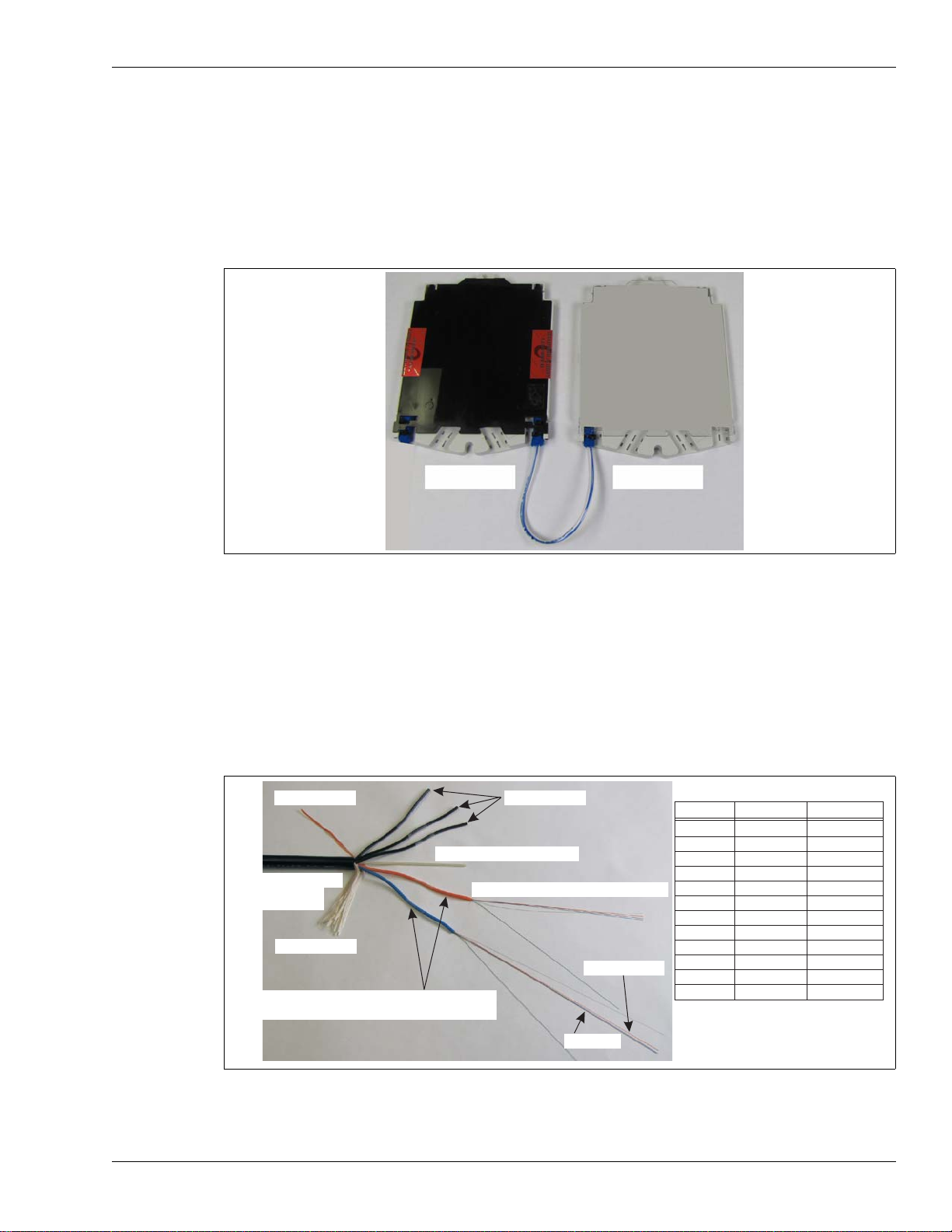
Figure 5: FiberPatrol outdoor splice components
Figure 6: FiberPatrol sensor cable description
end module splice tray
fiber # color
1
2
3
4
5
6
7
8
9
10
11
12
blue
orange
green
brown
gray
white
red
black
yellow
purple
rose
aqua
designation
S1
S2
dark
dark
dark
dark
dark
dark
dark
dark
dark
dark
blue tube fiber designations
3 mm color-coded 12-fiber buffer tubes
filler tubes
E-glass strength rod
ripcord
MDPE outer jacket
S2 (orange)
S1 (blue)
kevlar filler
11.4 mm OD
with water blocking gel
9/125 µm with 250 µm coating
FiberPatrol components
Page 12 FiberPatrol Site Planning & Installation Guide
Cable ties
FiberPatrol sensor cable is attached to the fence with stainless steel cable ties. The stainless steel
cable ties provide long life and a high level of security. A cable tie tool is required to attach the
stainless steel ties to the fence. The stainless steel cable ties are available with bare metal or vinyl
coated in lengths of 8, 14, and 20 inches. For situations in which the FiberPatrol cable will be
installed on a temporary fence and will be redeployed later, UV resistant polyethylene cable ties
are recommended.
Sensitivity loops
Corner posts, terminal posts and heavy gauge tension posts generally have a dampening effect on
nearby fence vibrations. To compensate for this, use sensitivity loops at all corner posts, terminal
posts and heavy gauge tension posts on the fence. The sensitivity loops provide additional sensor
cable for areas that typically produce lower levels of fence noise (see Figure 32).
Service loops
Service loops provide extra sensor cable for making future repairs, and for making fusion splices.
A 10 m (33 ft.) service loop is recommended for every 300 m (984 ft.) of installed sensor cable. A
10 m service loop is also recommended on the hinged side of each gate that is protected by
sensor cable. In addition, a 10 m (33 ft.) splice point service loop is required for each section of
sensor cable at all splice enclosure locations. A 10 m service loop is typically comprised of 5
circular loops of cable with a 60 cm (2 ft.) diameter (see Figure 34).
Isolation loops
Isolation loops are optional, but are recommended for situations where a zone needs to be
isolated from adjacent zones (e.g., gate isolation). Isolation loops are also recommended as a
buffer between detecting sensor cable and software defined non-detecting cable. Fence-mounted
isolation loops use 14 in. steel cable ties to secure 7 loops of sensor cable to the fence. The 7
loops have a 60 cm (2 ft.) diameter, which requires approximately 13 m of sensor cable.
Figure 7: FiberPatrol sensor cable/non-detecting lead cable
cross section
color coded individual fiber
color coded 12 fiber buffer tube
PE filler unit (X 3)
central strength member
binder tape
ripcord
MDPE outer jacket
waterblock system
color coded 6 fiber buffer tube

FiberPatrol components
FiberPatrol Site Planning & Installation Guide Page 13
Buried vault
Another method for zone to zone isolation is to move the sensor cable off the fence through
conduit and then form a 13 m (43 ft.) isolation loop inside a buried vault. The cable is then run
through another section of conduit and back onto the fence where it continues as another zone.
Figure 8: provides the dimensions for the FiberPatrol buried vault.
Figure 8: Buried vault dimensions
46 cm
69 cm
(27 in.)
(18 in.)
49.5 cm
(19.5 in.)
82 cm
(32.25 in.)
103 cm
(40.5 in.)
top view
end view side view
NOTE: dig hole 51 cm (20 in.) D X 76 cm (30 in.) W X 107 cm (42 in.) L
FiberPatrol Site Planning & Installation Guide Page 13
2 Site planning
FiberPatrol configurations
The recommended method for installing FiberPatrol sensor cable is to use the minimum number of
splices possible; i.e., run a single length of cable from the equipment room to the fence, and
continue for as far as site conditions will allow you to go. Use splices for the start module, the end
module, and at any site features where a continuous run of cable is impractical or impossible.
Loop configurations
The loop configuration provides single cable cut redundancy for a closed perimeter. The sensor
unit is located anywhere along the perimeter length with the start and end points of the detecting
sensor cables co-located in a splice enclosure. Non-detecting lead cable carries the signal from
the sensor unit to the start point of the detecting cable. The two sensing fibers S1 and S2 run in
different directions around the perimeter. In the event of a cut or severely damaged sensor cable,
detection will continue around the perimeter in both directions to the location of the damage. There
are two types of redundant loop configurations, fully closed and partially closed. Figure 9 provides
a comparison of the two.
Figure 9 FiberPatrol example fully closed & partially closed configuration comparison
FiberPatrol sensor cable
perimeter fence
administration
administration
fully closed perimeter partially closed perimeter
FiberPatrol configurations
Page 14 FiberPatrol Site Planning & Installation Guide
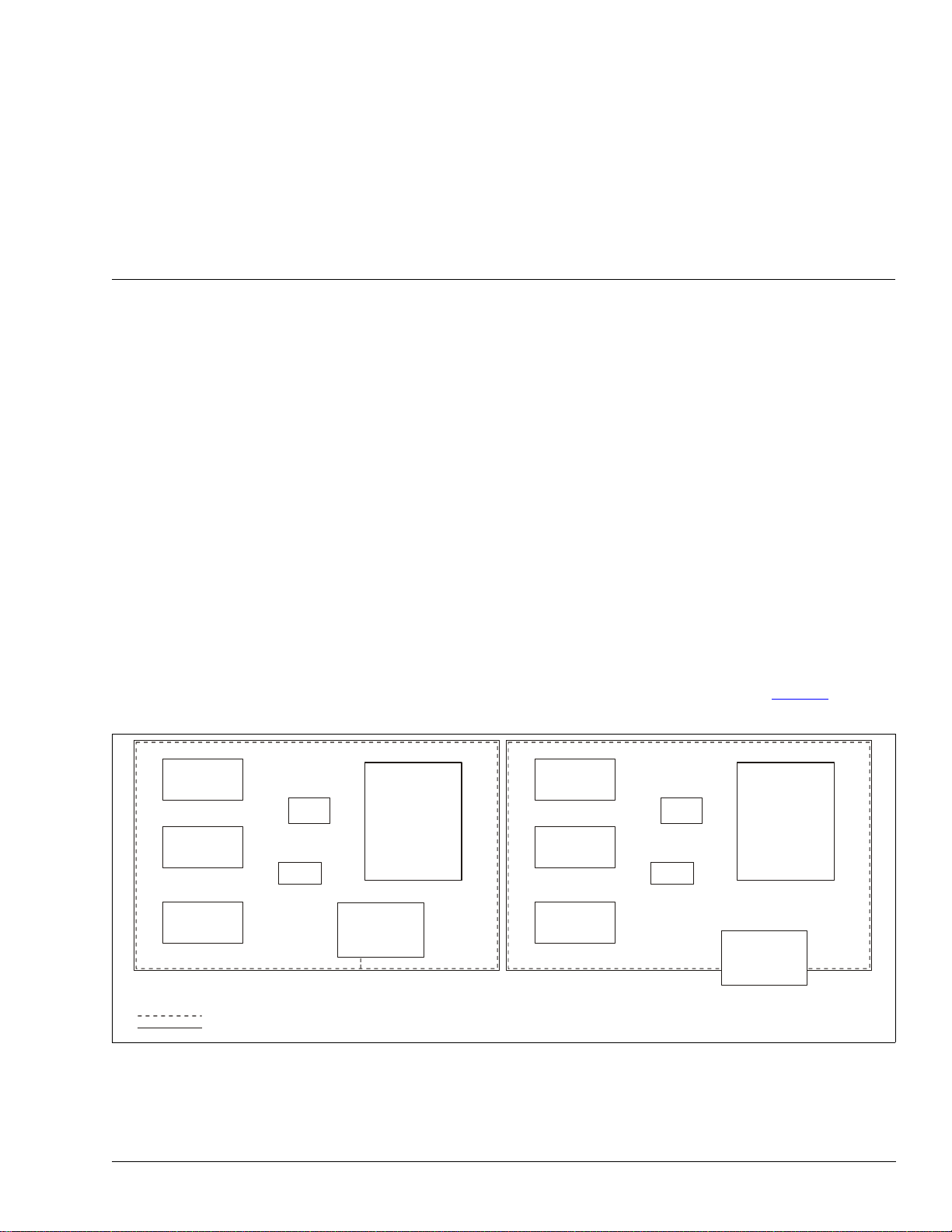
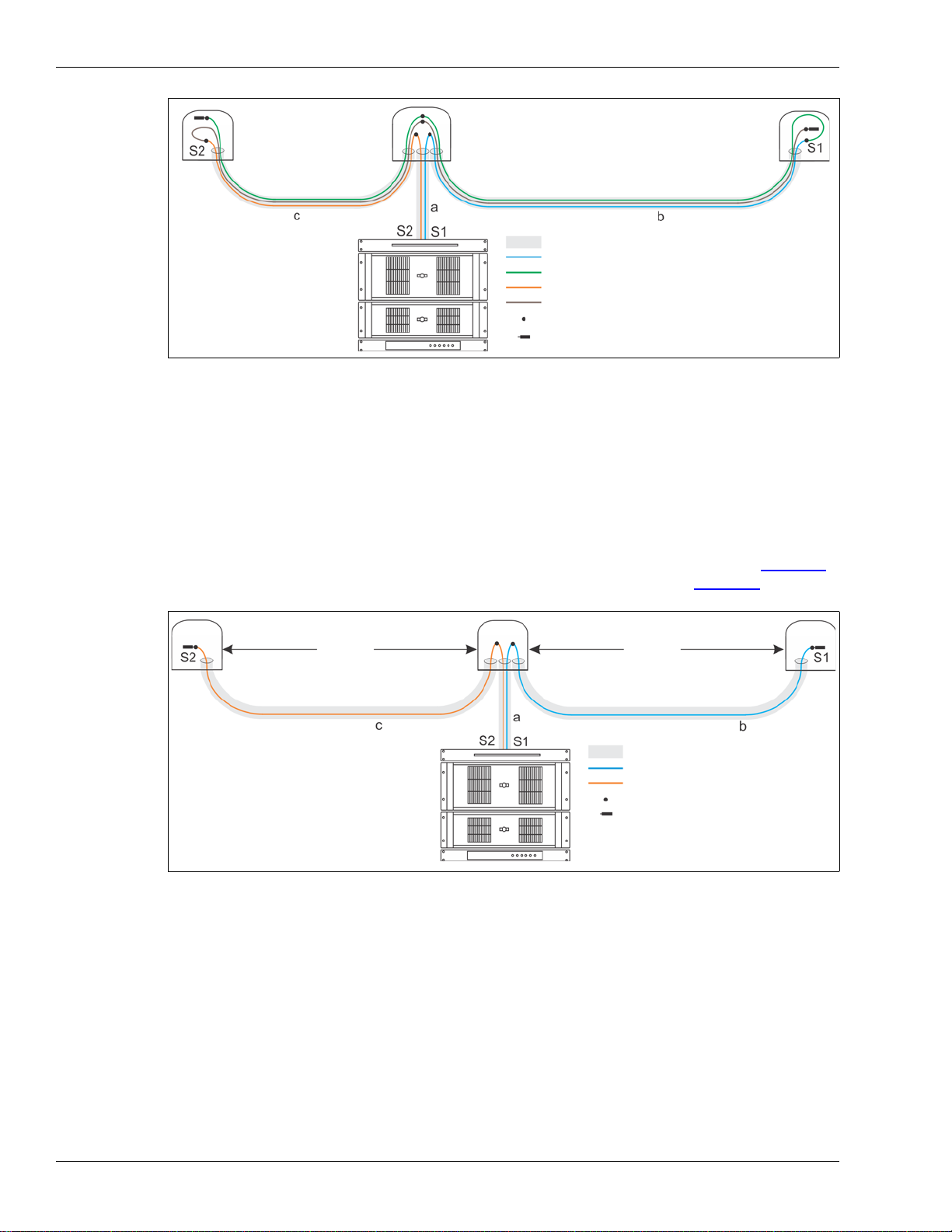
In some instances it is desirable to have a single length of cable running between the equipment
room and the start of the perimeter. This is most common in installations where the sensor unit
equipment is located at a distance from the perimeter. In this case, a dual start/dual end module is
located in the equipment room, and a single lead cable runs to the perimeter fence. Fusion splices
are used to join S1 (blue) in the lead cable to S1 (blue) in the detecting cable. S1 blue runs around
the perimeter and is spliced to S1 (green) in the lead cable going back to the end module in the
equipment room. S2 (orange) in the lead cable is spliced to S2 (orange) in the detecting cable. S2
orange runs around the perimeter and is spliced to S2 (brown) in the lead cable going back to the
end module in the equipment room (see Figure 10).
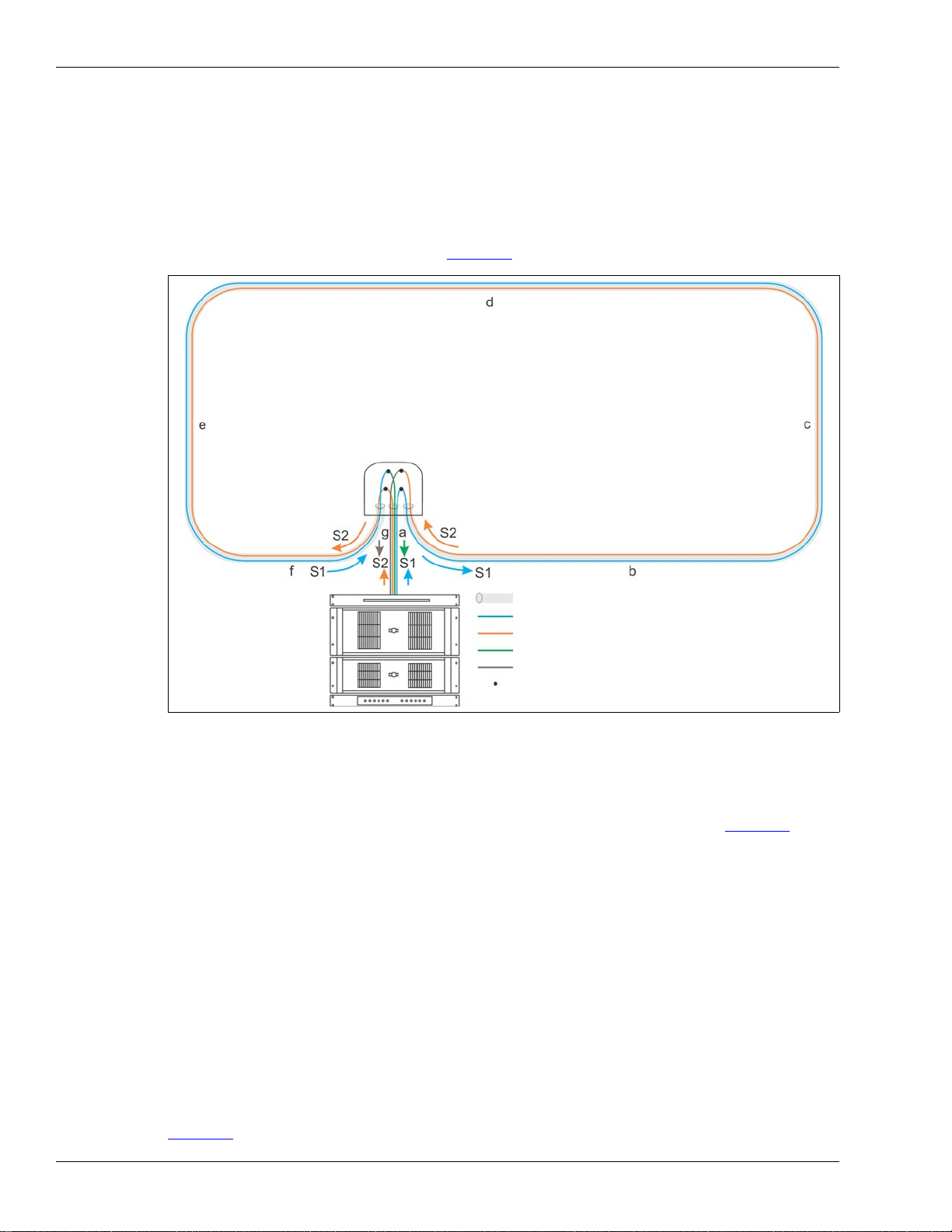
A fully closed perimeter can also be obtained by using a dual start module in the equipment room
and a dual end module located inside a splice enclosure at the start of the perimeter. A single lead
cable runs from the equipment room to the perimeter and S1 and S2 run in opposite directions
around the perimeter with both terminated in the start point splice enclosure (see Figure 11).
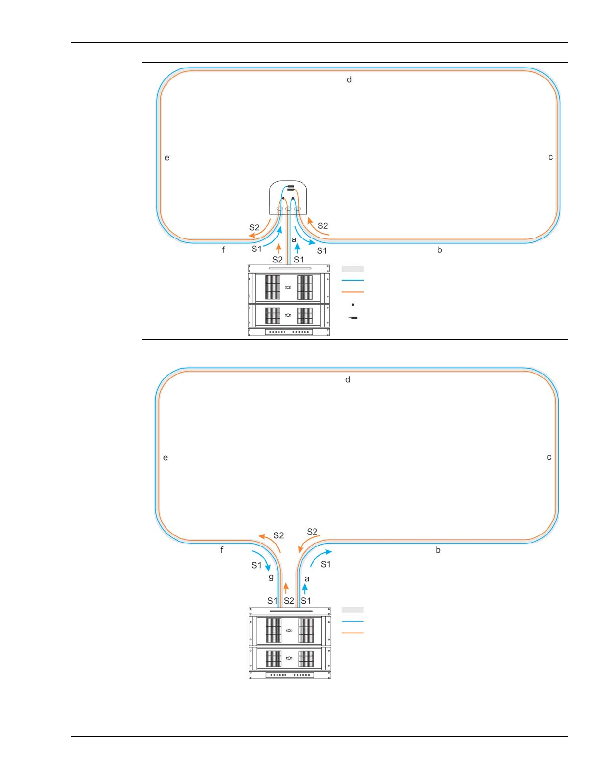
The partially closed loop configuration uses a dual start/end module in the equipment room and
has two lead cables. This configuration also provides single cut redundancy for a partially closed
perimeter. The two sensing fibers S1 and S2 run in different directions around the perimeter. In the
event of a cut or severely damaged sensor cable, detection will continue around the perimeter in
both directions to the point of the damage.
Open-ended loop configuration
The open-ended loop configuration provides single fiber break redundancy for an open-ended
perimeter. The sensor unit can be located anywhere along the perimeter length with the start and
end points of the detecting sensor cables located at opposite ends. The two sensing fibers S1 and
S2 run in different directions for the length of the cable. Two additional fibers are used to bring the
lead fibers to the opposite ends of the perimeter, where they are spliced to the detecting fibers.
The two detecting fibers run from one end of the perimeter to the other in opposite directions (see
Figure 13).
Figure 10 FiberPatrol fully closed redundant loop configuration
FiberPatrol sensor cable
fiber optic cable (sensor cable/lead cable)
S1 (sensor fiber 1 - internal to fiber optic cable)
S2 (sensor fiber 2 - internal to fiber optic cable)
fusion splice
splice enclosure
sensor unit
equipment
Note: Cable length = a + b + c + d + e + f + g
dual start/end module
S1 (sensor fiber 1 - spliced return to sensor unit)
S2 (sensor fiber 2 - spliced return to sensor unit)
FiberPatrol configurations
FiberPatrol Site Planning & Installation Guide Page 15
Figure 11 FiberPatrol fully closed redundant loop configuration
Figure 12 FiberPatrol partially closed redundant loop configuration
FiberPatrol sensor cable
fiber optic cable (sensor cable/lead cable)
S1 (sensor fiber 1 - internal to fiber optic cable)
S2 (sensor fiber 2 - internal to fiber optic cable)
fusion splice
fiber optic termination
splice enclosure
sensor unit
equipment
Note: Cable length = a + b + c + d + e + f
dual end module
FiberPatrol sensor cable
fiber optic cable (sensor cable/lead cable)
Note:
S1 (sensor fiber 1 - internal to fiber optic cable)
S2 (sensor fiber 2 - internal to fiber optic cable)
sensor unit equipment
Cable length = a + b + c + d + e + f + g
includes
dual start/
dual end modules
FiberPatrol configurations
Page 16 FiberPatrol Site Planning & Installation Guide
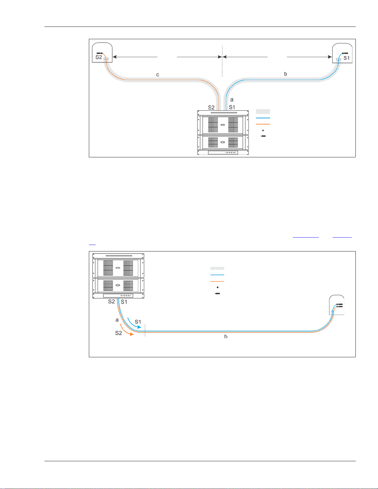
Split configuration
The split configuration provides extended length coverage for an open-ended perimeter. To get the
maximum length coverage the sensor unit is located near the mid-point of the protected section of
fence. The sensor cable runs in opposite directions along the fence with each end module located
up to 25 km away from the sensor unit. One sensor fiber provides detection in each direction with
S1 running in one direction and S2 running the opposite way. A splice enclosure is required at the
start point on the fence to use one lead cable from the sensor unit to the perimeter (see Figure 14).
Using two lead cables eliminates the need to have the start point splice (see Figure 15).
Figure 13 FiberPatrol open-ended loop configuration
Figure 14 FiberPatrol split configuration (1 lead cable)
fiber optic cable (sensor cable/lead cable)
Note:
S1 (sensor fiber 1 lead)
S2 (sensor fiber 2 lead)
fusion splice
fiber optic termination
splice enclosure splice enclosure
sensor unit equipment
Cable length = a + 2b + 2c
S1 (sensor fiber 1 detecting)
S2 (sensor fiber 2 detecting)
single end module
splice enclosure
single end module
includes dual start module
fiber optic cable
Note:
S1
S2
fusion splice
fiber optic termination
splice enclosure splice enclosure
sensor unit equipment
Cable length = 2a + b + c
single end module
splice enclosure
single end module
includes dual start module
25 km
(max.)
25 km
(max.)
FiberPatrol configurations
FiberPatrol Site Planning & Installation Guide Page 17
Line configurations
The line configuration is typically used when the sensor unit equipment is located at one end of the
protected perimeter, and the perimeter extends away from the equipment room in one direction.
The line configuration does not provide single cut redundancy for the full length of the sensor
cable. In the event of a cut or severely damaged sensor cable, detection will continue between the
start of the detecting sensor cable and the cut/damaged point in the cable. Figure 16 and Figure
17 illustrate the line configuration.
If necessary, the non-detecting lead cable can be spliced to the detecting cable at the start point of
the sensor cable. Splices may also be required for other site specific features.
Figure 15 FiberPatrol split configuration (2 lead cables)
Figure 16 Recommended line configuration
fiber optic cable
Note:
S1
S2
fusion splice
fiber optic termination
splice enclosure
sensor unit equipment
Cable length = 2a + b + c
single end module
splice enclosure
single end module
includes dual start module
25 km
(max.)
25 km
(max.)
fiber optic cable (sensor cable/lead cable)
S1 (sensor fiber 1 - internal to fiber optic cable)
S2 (sensor fiber 2 - internal to fiber optic cable)
fusion splice
fiber optic termination
splice enclosure
sensor unit
equipment
beginning of detecting cable
non-detecting lead cable
NOTES: Splices may be required at the beginning of the detecting cable and at other site specific features,
due to installation constraints and conditions.
Cable length = a + b
FiberPatrol configurations
Page 18 FiberPatrol Site Planning & Installation Guide
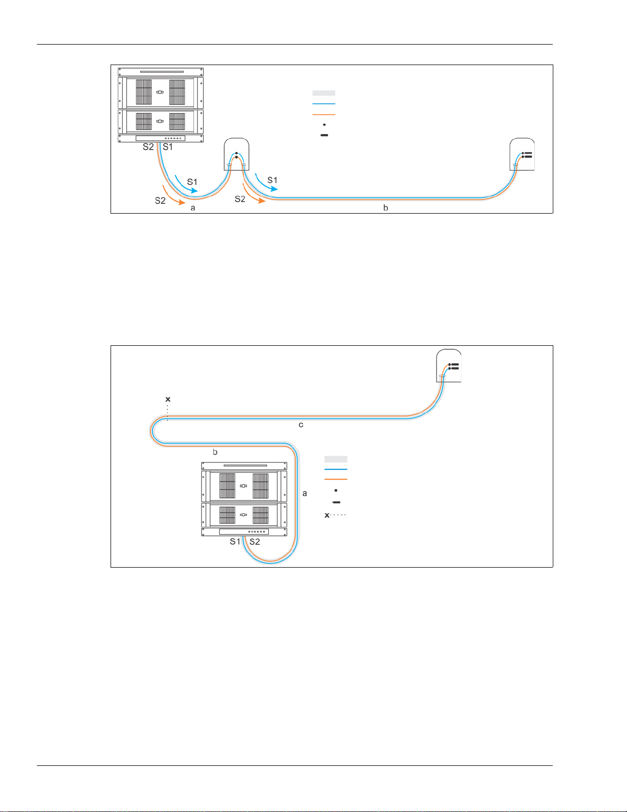
Extended lead configuration
The extended lead configuration is a variation of the line configuration in which lead cable runs
from the sensor unit to one end of the perimeter. The detecting fibers S1 and S2 run the full length
of the perimeter from one end to the other. The extended lead configuration does not provide
single cut redundancy for the full length of the sensor cable. In the event of a cut or severely
damaged sensor cable, detection will continue between the start of the sensor zone, and the cut/
damaged point in the cable.
Figure 17 line configuration with start point splice
Figure 18 FiberPatrol extended lead configuration
fiber optic cable (sensor cable/lead cable)
S1 (sensor fiber 1 - internal to fiber optic cable)
S2 (sensor fiber 2 - internal to fiber optic cable)
fusion splice
fiber optic termination
splice enclosure
splice enclosure
sensor unit
equipment
Note: Cable length = a + b
FiberPatrol sensor cable
fiber optic cable (sensor cable/lead cable)
Note:
S1 (sensor fiber 1 - internal to fiber optic cable)
S2 (sensor fiber 2 - internal to fiber optic cable)
fusion splice
fiber optic termination
splice enclosure
sensor unit
equipment
Cable length = a + b + c
dual end module
indicates software defined start of detection

Site survey
FiberPatrol Site Planning & Installation Guide Page 19
Site survey
The first step in installing a FiberPatrol fence protection system is to conduct a detailed site survey.
The survey assesses the site conditions to determine the specific installation requirements
including the fence type, fence condition, fence length, zone layouts, sensor cable route, non-
detecting lead cable length, length of sensor cable required to cover the perimeter, and the
location for the electronic components.
Create a scale drawing of the site (e.g., CAD drawings), which indicates the locations of:
• fences (include type and condition)
• gates (include type and size)
• buildings and other structures
• roads, driveways, sidewalks, paths, parking areas
• trees, bushes, dense vegetation (near perimeter)
• location of sensor cable
• other existing or planned security devices (e.g., CCTV cameras, security lighting, etc.)
Fences
The fence must be properly installed, maintained, and tensioned, to provide effective intrusion
detection with FiberPatrol. The fence should be uniform in height and quality, and should be high
enough to present an effective barrier against climb-over intrusions. It is also recommended that a
climb-over barrier, such as barbed wire or concertina, be installed along the top of the fence. The
condition of the fence is critical to the efficient operation of the FiberPatrol sensor system. Breaks
in the fence structure, or slack portions of the fence fabric, will inhibit the transmission of the fence
vibrations to the sensor cable. Poor fence conditions can also cause metal on metal contact noise
that will result in nuisance alarms.
Chain-link fences
The chain-link fence fabric should meet the following specifications:
• maximum range of deflection 10 cm (4 in.) when a 22.5 kg (50 lb) force is applied
perpendicular to the center of a panel (pushing and pulling) (based on 3 m, 10 ft. post spacing)
• minimum height of 2.4 m (8 ft.) with climb-over deterrent hardware securely mounted on top
Weld-mesh fences
A typical weld-mesh fence section consists of 3 mm (0.1 in.) diameter steel wire welded into a grid
configuration, with horizontal spacing differing from the vertical spacing. These fence sections are
secured to fence posts and to the adjacent fence panel sections. The sections of weld-mesh fence
are either welded together or connected using clips, bolts or rivets. The minimum recommended
Note Fences used in conjunction with the FiberPatrol sensor must meet
industry standards for security fences.
Note Any fence movement which can cause metal-to-metal contact is a
potential source of nuisance alarms.
This manual suits for next models
11
Table of contents
Other SENSTAR Accessories manuals

SENSTAR
SENSTAR FiberPatrol FP400 User manual

SENSTAR
SENSTAR UltraWave BR100 User manual

SENSTAR
SENSTAR FPS 2-2 User manual

SENSTAR
SENSTAR FlexZone User manual

SENSTAR
SENSTAR FiberPatrol FP1150 Series User manual

SENSTAR
SENSTAR FlexPS User manual

SENSTAR
SENSTAR OmniTrax User manual

SENSTAR
SENSTAR IntelliFIBER User manual

SENSTAR
SENSTAR FlexZone WGS User manual
Popular Accessories manuals by other brands

ekwb
ekwb EK-FC980 GTX Strix Backplate Installation and mounting manuals

Hytronik
Hytronik HC005S/I Installation and instruction manual

Philips
Philips SVC2522W Specification sheet

BEA
BEA WIZARD PLUS user guide

Pilz
Pilz PSEN i1 operating instructions

Pepperl+Fuchs
Pepperl+Fuchs ML100-55-G/95/102 quick start guide


