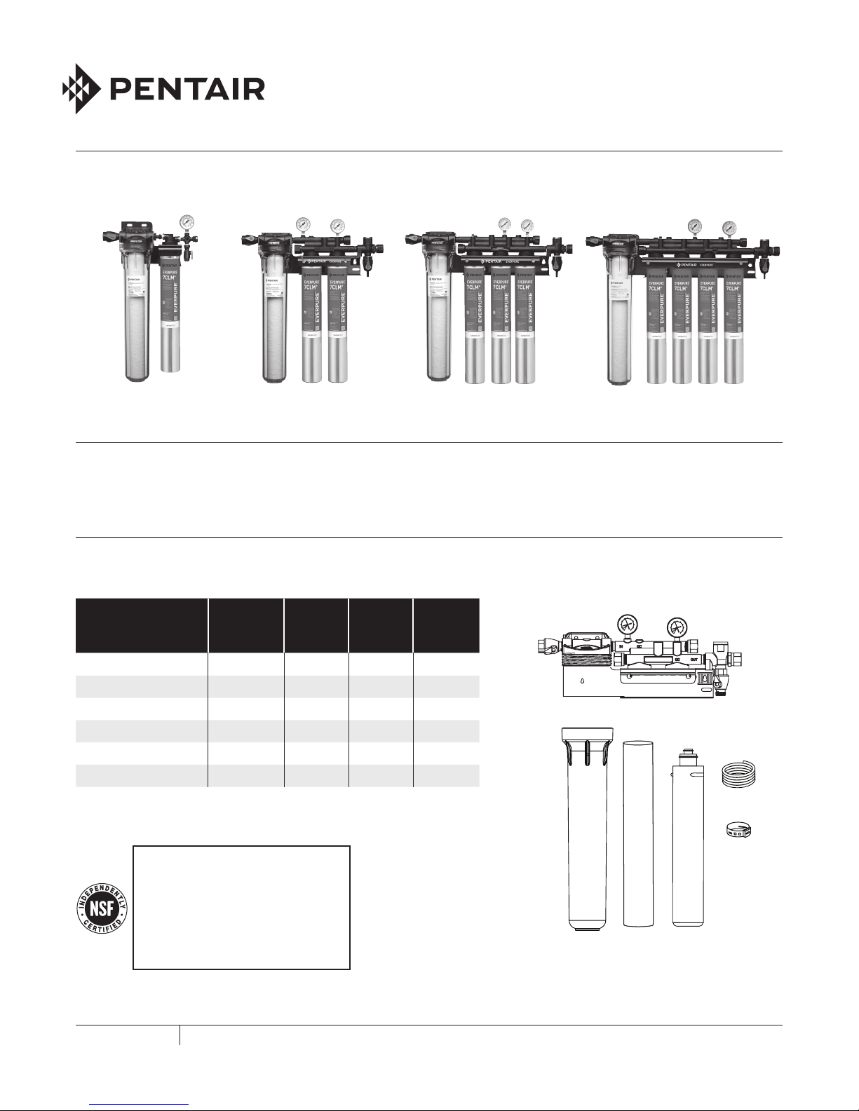
7COLDRINK -7CLM+SERIES SYSTEMS INSTALLATION AND OPERATION GUIDE
OPERATING SPECIFICATIONS*
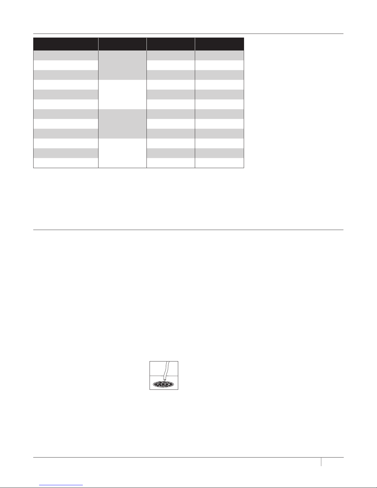
Combined Model Name Part Number Flow Rate Capacity
Coldrink System 1 - 7CLM+
EV9771-21
1.67 gpm (6.32 Lpm) 7,500 gals (28,390 L)
Coldrink System 1 - 7CLM+1.33 gpm (5.03 Lpm)†9,500 gals (35,961 L)†
Coldrink System 1 - 7CLM+1.00 gpm (3.78 Lpm)†12,600 gals (47,696 L)†
Coldrink System 2 - 7CLM+
EV9771-22
3.34 gpm (12.64 Lpm) 15,000 gals (56,781 L)
Coldrink System 2 - 7CLM+2.66 gpm (10.06 Lpm)†19,000 gals (71,922 L)†
Coldrink System 2 - 7CLM+2.00 gpm (7.57 Lpm)†25,200 gals (95,392 L)†
Coldrink System 3 - 7CLM+
EV9771-23
5.01 gpm (18.96 Lpm) 22,500 gals (85,171 L)
Coldrink System 3 - 7CLM+4.00 gpm (15.14 Lpm)†28,500 gals (107,884 L)†
Coldrink System 3 - 7CLM+3.00 gpm (11.35 Lpm)†37,800 gals (143,088 L)†
Coldrink System 4 - 7CLM+
EV9771-24
6.68 gpm (25.29 Lpm) 30,000 gals (113,562 L)
Coldrink System 4 - 7CLM+5.33 gpm (20.17 Lpm)†38,000 gals (143,845 L)†
Coldrink System 4 - 7CLM+4.00 gpm (15.14 Lpm)†50,400 gals (190,784 L)†
*For individual cartridge specifications, refer to cartridge literature.
†Not Performance Tested or Certified by NSF.
Temperature: 35 - 100°F (2 - 38°C)
Pressure: 10 -125 psi (0.7 - 8.6 bar), non-shock
For cold water use only.
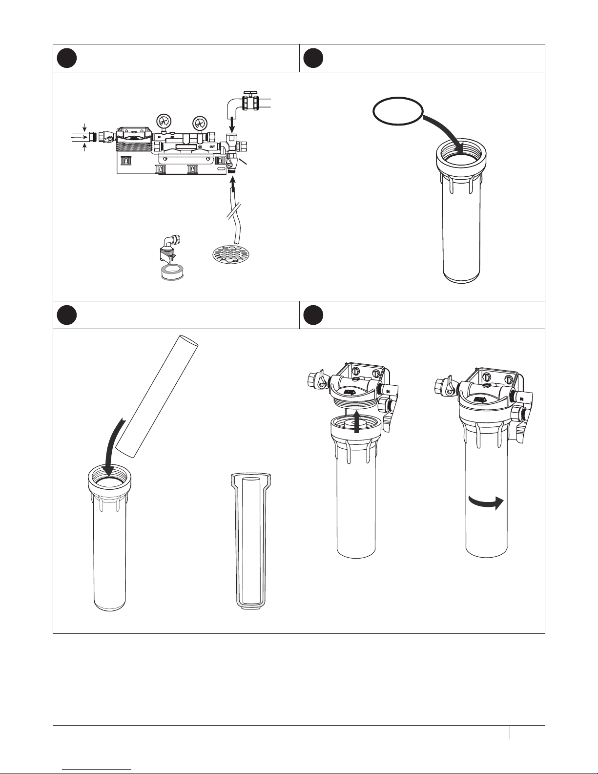
INSTALLATION
1. Use the predrilled mounting holes in the manifold bracket
as guides. Mark and drill anchor hole. Mount securely.
2. Shut off power to equipment.
3. Connect outlet port of Coldrink - 7CLM+Series System to
the equipment served. Always use an NSF-approved pipe
dope or plumbers tape at all connections. Use a backup
wrench on all fittings while connecting to avoid excessive
stress on the system components.
4. Install a manual shut-off valve leading to the system
for servicing.
5. Connect inlet water line to inlet valve of Coldrink – 7CLM+
Series Systems. Connect a minimum of 1/2" water line to
the Single Coldrink - 7CLM+ Series System for flushing.
All other manifolds use a 3/4-inch water line.
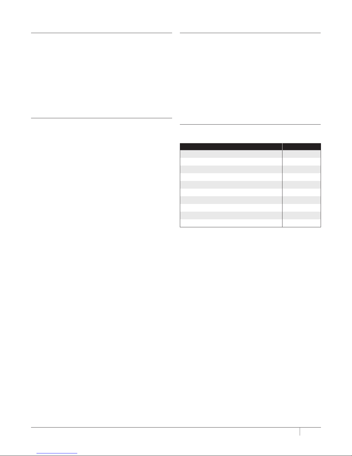
6. Connect tubing to the flushing valve and run to drain. The
cross fitting has a flushing valve installed on the bottom.
NOTE: Some municipal plumbing codes
and good sanitary practices
require an air gap at the drain
termination point.
Air Gap
7. Shut off the system inlet valve located on the inlet of the
prefilter head.
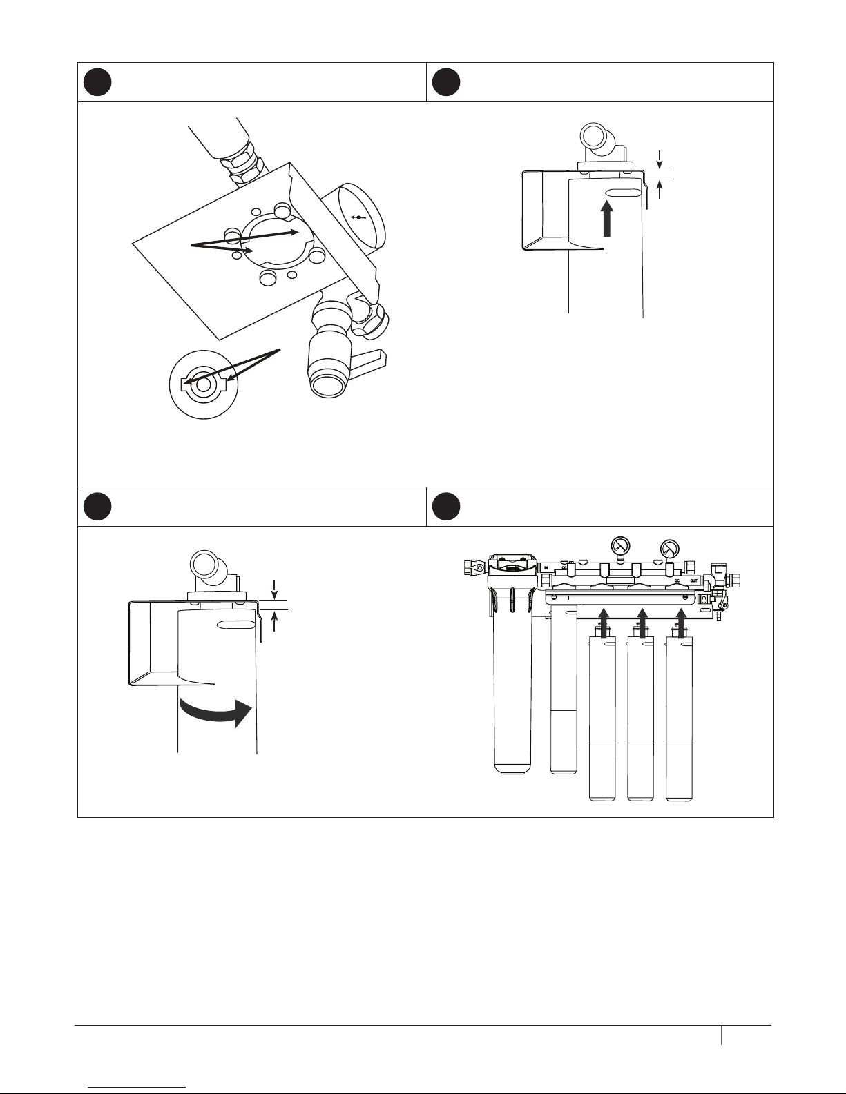
8. Check to be sure the o-ring on the prefilter housing
is sufficiently lubricated. Use a good grade of silicone
lubricant, if needed. Position the prefilter cartridge on
guide seat in the bottom of the bowl. Then thread the
bowl into the head by hand. Use a sump wrench to snug
the bowl onto the head.
9. Install the carbon filter cartridge(s) into the filter head(s)
following directions on the cartridge label or as shown in
the Cartridge Change Procedure section illustrations.
CAUTION: Unused manifold ports must be plugged. Any
ports not plugged will leak.
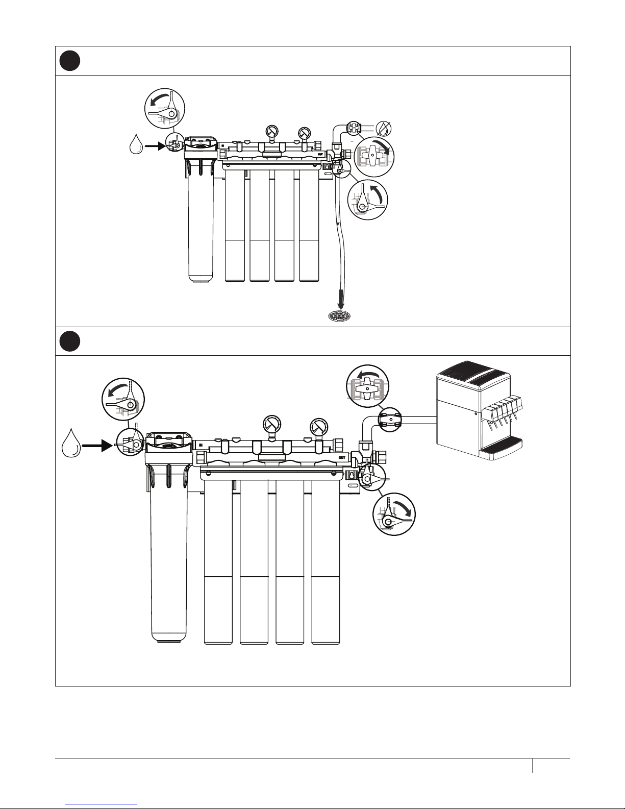
10. Turn on inlet water to the filter system and check for leaks.
11. Open the flushing valve and flush the newly installed
cartridge(s) by running feed water for five (5) minutes at
full flow or a minimum of 25 gallons (94.6 liters) through
flush port. This procedure will help set the filtering
media and purge any air and fines, ensuring maximum
filter life.
12. Disconnect the outlet line and flush one (1) gallon (3.8
liters) of water through the outlet. This will clear any
fines that may have entered through the outlet from the
previous flushing procedure. This is only applicable on
the first installation of the system, or when there is air
trapped in the outlet line due to maintenance.
13. After flushing, close the flushing valve, turn on power
to equipment, and plug the EverguardTM Low Pressure
Alarm (LPA), if so equipped, into the electrical outlet. The
system is ready for operation.