manuals.online logo
Brands
  1. Home
  2. •
  3. Brands
  4. •
  5. Evolution Aqua
  6. •
  7. Water Filtration System
  8. •
  9. Evolution Aqua Tempest User manual

Evolution Aqua Tempest User manual

INSTRUCTION MANUAL
UK/EU English
TEMP110032021MAN
IMPORTANT:
Ensure slide valves are fitted to inlet and outlet of all Tempest filters.
Read the instructions carefully before carrying out the installation.
Evolution Aqua Ltd. Kellet Close - Wigan - Lancashire - United Kingdom - WN5 0LP
t +44 (0) 1942 216554 - e[email protected] - wwww.evolutionaqua.com
2
ABOUT THE TEMPEST FILTER
The Tempest filter is an innovative polishing system for ponds that will help to
deliver crystal clear water. Designed to be used in conjunction with any filtration
system, the Tempest offers additional mechanical and biological filtration.
The Tempest filter can also be used on quarantine systems or as a standalone
filter on smaller ponds up to 5,000 Litres / 1,100 Gallons / 1,320 US Gallons.
The Tempest filter is easy to install and is simple and quick to clean, by way of
a unique, patent pending air syphon design. During the cleaning process, air is
drawn into the filter as it empties which causes the water to agitate, effectively
cleaning the K+Media.
Using Evolution Aqua’s K+Media as the filter media, particles down to one micron
can be filtered. On a single pass, testing has proven our media capable of removing
all particles down to 25 micron when used at the optimum flow rate. Not only
that, K+Media is the result of extensive research and development and is moulded
with minerals for faster maturation times.
Evolution Aqua filter media has been independently tested by
IFTS (Institut de la Filtration et des Techniques Séparatives).
IFTS International Filter Testing Services is the international
reference for solid-liquid separation. Founded in 1981, IFTS is an independently
regulated, ISO 17025 accredited, laboratory and research center focusing on
liquid filtration and separation science. IFTS quality management system is
certified to ISO 9001:2015.
3
K+MEDIA
K+Media is designed and manufactured by Evolution Aqua. This advanced
media, with its innovative design and class leading surface area provides
enhanced biological and mechanical filtration. As Evolution Aqua extrude the
K+Media, minerals and enzymes are added to the raw material.
The result of this process, unique to Evolution Aqua, is a filtration media that
not only outperforms most of its competitors due to its large protected surface
area, but also answers the problem of how to speed up the time taken to
mature your filter.
- Class leading total surface area 1350m2per m3
- Vast protected surface area 1025m2per m3
- Filters mature faster with K+Media
- Minerals incorporated into each piece during extrusion
- Unique design for stable bio-film development
- Exceptional solids removal
4
TEMPEST FILTER PARTS
Tempest Filter filled with
7 litres of K+Media
1½" Slide Valve
Qty x 2
1½" Pipe Clip Bracket
Qty x 2
Waste Valve Assembly
100mm 1½" Connector Pipe
Qty x 2
YOU WILL ALSO REQUIRE:
- Solvent Weld Adhesive
(EA Code: S79-0-500)
- Tools and fixings for installation
5
TEMPEST FILTER OVERVIEW
1½"
OUTLET
1½"
INLET
1½"
Slide Valve
(Inlet)
1½"
Slide Valve
(Outlet)
K+Media
(Floats to
top during
operation)
Air Inlet
Cover Cap
1½" Pipe Clip
Bracket
1½" Pipe Clip
Bracket
1½"
Connector
Pipe
1½"
Connector
Pipe
TO WASTE
1" HOSETAIL
Waste
Valve
Assembly
6
TEMPEST FILTER SPECIFICATIONS
INLET 1½” (UK / USA) / 50mm (EU)
OUTLET 1½” (UK / USA) / 50mm (EU)
DRAIN HOSETAIL SIZE 1” (UK / USA) / 32mm (EU)
MAXIMUM FLOW RATE 7,500 LPH / 1,650 GPH / 1,980 US GPH
OPTIMUM FLOW RATE 5,000 LPH / 1,100 GPH / 1,320 US GPH
K+MEDIA SUPPLIED 7 Litres
WATER VOLUME IN FILTER 27 Litres / 5.9 Gallons / 7.1 US Gallons
The Tempest filter can also be used on quarantine systems or as a standalone
filter on smaller ponds up to 5,000 litres / 1,100 gallons / 1,320 US gallons.
1100mm
790mm
Centre of pipe to centre of pipe
250mm
130mm
45mm
105mm
205mm
PUMP
IN
AIR
INLET WASTE
VALVE
OUTLET
TO
POND
7
TEMPEST FILTER SET-UP
Follow these step by step instructions to set-up your Tempest filter ready for
installation.
STEP 1: Familiarise yourself with all the components from the parts bag.
STEP 2: At the bottom of the filter, screw on the waste valve assembly hand tight
only, do not use tools. (Ensure the o-ring is seated inside the screw cap)
STEP 3: Solvent weld one end of the 100mm length of 1½" connector pipe into the
inlet of the Tempest. Push pipe into the inlet until it stops.
STEP 4: Solvent weld the slide valve onto the opposite end of the 1½" connector
pipe. Push slide valve onto pipe until it stops.
STEP 5: Take the second 100mm length of 1½" connector pipe and solvent weld it
into the outlet of the Tempest filter. Push pipe into the outlet until it stops.
STEP 6: Solvent weld the slide valve onto the opposite end of the 1½" connector
pipe. Push slide valve onto pipe until it stops.
STEP 7: Allow the glue to set for atleast 5 hours.
The Tempest is now set-up ready for installation.
The slide valves fitted allow connection to 1½" pressure pipe.
If installing the Tempest Filter using flexible hose you will need to fit a reducing
sleeve (EA Code: M35-050) and a 1½" solvent stepped hosetail
(EA Code: HOSETAIL15) inside each slide valve.
IMPORTANT: Ensure the supplied o-ring is fitted inside the waste
valve assembly before screwing on to waste outlet.
ADVICE: We recommend having the slide valves face each other,
so the top valve points down and the bottom valve points up.
8
TEMPEST FILTER SET-UP
Follow these instructions to set-up your Tempest filter ready for installation.
STEP 1: Familiarise yourself with all
the components from the parts bag.
STEP 3: Solvent weld one end of the
100mm length of 1½" connector pipe
into the inlet of the Tempest. Push
pipe into the inlet until it stops.
STEP 2: With o-ring in place inside
collar, screw on the waste valve
assembly to the bottom of the
Tempest filter, hand tight only.
(Do not use tools)
STEP 4: Solvent weld the slide valve
onto the opposite end of the 1½"
connector pipe. Push slide valve onto
pipe until it stops.
IMPORTANT: Ensure the supplied o-ring is fitted inside the waste valve
assembly before screwing on to waste outlet (See step 2).
PARTS NEEDED: You will need solvent weld adhesive and a brush
for gluing.
SOLVENT WELD
SOLVENT WELD
9
TEMPEST FILTER SET-UP
STEP 5: Take the second 100mm
length of 1½" connector pipe and
solvent weld it into the outlet of the
Tempest filter. Push pipe into the
outlet until it stops.
STEP 7: Allow the glue to set for
atleast 5 hours.
The slide valves fitted allow connection to
1½" pressure pipe. If installing the Tempest Filter
using flexible hose you will need to fit a reducing
sleeve (EA Code: M35-050) and a 1½" solvent
stepped hosetail (EA Code: HOSETAIL15) inside
each slide valve.
The Tempest is now set-up ready for installation.
STEP 6: Solvent weld the slide valve
onto the opposite end of the 1½"
connector pipe. Push slide valve onto
pipe until it stops.
WAIT
SOLVENT WELD SOLVENT WELD
10
TEMPEST FILTER INSTALLATION IDEAS
TYPICAL INSTALLATIONS WITH A FILTER
FLOW RATES
Install a Tempest Filter after a primary filter on a GRAVITY FED SET-UP, such as
the Nexus+, and after a UV Clarifier, such as an evoUV. The slide valves on the
Tempest Filter enable connection to 1½" pressure pipe.
The installation example shown below has a by-pass that will enable you to
increase the flow through your pond while maintaining the optimum flow through
the Tempest Filter. Installing ball valves on the pipe work will help you regulate
the flow. The return from the Tempest can go back to the centre of your Nexus+
or back into the pond.
To allow the Tempest filter to give the best performance, it is important that the
flow rate is no more than the 5,000 litres per hour. These installation examples
show a by-pass that will enable you to increase the flow through the pond.
IMPORTANT: Ensure slide valves are fitted to inlet and outlet of
the Tempest filter.
IMPORTANT: We always recommend fitting unions when installing in
line equipment on your system which help when removing the filter.
IMPORTANT: Optimum flow rate through the Tempest filter is
5,000 LPH / 1,100 GPH / 1,320 US GPH
POND
RETURN INTO NEXUS OR INTO POND
SLIDE
VALVE
BALL
VALVE
SLIDE
VALVE
11
TYPICAL INSTALLATIONS WITH A FILTER
Installed on a pressurised system with a K1 Micro Bead, Nexus+, EazyPod.
The slide valves on the Tempest Filter enable connection to 1½" pressure pipe.
The installation example shown below has a by-pass that will enable you to
increase the flow through your pond while maintaining the optimum flow through
the Tempest Filter. Installing ball valves on the pipe work will help you regulate the
flow. The return from the Tempest and the K1 Micro Bead go back to the pond.
IMPORTANT: Ensure slide valves are fitted to inlet and outlet of
the Tempest filter.
IMPORTANT: We always recommend fitting unions when installing in
line equipment on your system which help when removing the filter.
IMPORTANT: Optimum flow rate through the Tempest filter is
5,000 LPH / 1,100 GPH / 1,320 US GPH
TEMPEST FILTER INSTALLATION IDEAS
POND
SLIDE
VALVE
SLIDE
VALVE
BALL
VALVE
12
POND
POND
Return direct
to pond or via a
waterfall / blade
TEMPEST FILTER INSTALLATION IDEAS
TYPICAL STANDALONE TEMPEST FILTER INSTALLATIONS
Install a Tempest Filter on a quarantine system, or a standalone pond up to 5,000
litres, at the side of a pond or above the pond. The slide valves on the Tempest
Filter enable connection to 1½" pressure pipe. If installing the Tempest Filter using
flexible hose you will need to fit a reducing sleeve (EA Code: M35-050) and a
1½" solvent stepped hosetail (EA Code: HOSETAIL15) inside each slide valve.
OPTIMUM
FLOW RATE:
5,000 LPH
1,100 GPH
1,320 US GPH
IMPORTANT: Ensure slide valves are fitted to inlet and outlet of
the Tempest filter.
IMPORTANT: We always recommend fitting unions when installing in
line equipment on your system which help when removing the filter.
13
SKIMMER LINE INSTALLATION
Install a Tempest Filter on a skimmer line.
The slide valves on the Tempest Filter enable connection
to 1½" pressure pipe. If installing the Tempest Filter using
flexible hose you will need to fit a reducing sleeve
(EA Code: M35-050) and a 1½" solvent stepped hosetail
(EA Code: HOSETAIL15) inside each slide valve.
POND
OPTIMUM
FLOW RATE:
5,000 LPH
1,100 GPH
1,320 US GPH
IMPORTANT: Ensure slide valves are fitted to inlet and outlet of
the Tempest filter.
IMPORTANT: We always recommend fitting unions when installing in
line equipment on your system which help when removing the filter.
TEMPEST FILTER INSTALLATION IDEAS
14
TEMPEST FILTER INSTALLATION
MODULAR TEMPEST FILTER INSTALLATIONS
On larger systems that require a higher flow rate, multiple Tempest filters can
be installed in a modular system. The slide valves on the Tempest Filter enable
connection to 1½" pressure pipe. If installing the Tempest Filter using flexible
hose you will need to fit a reducing sleeve (EA Code: M35-050) and a 1½"
solvent stepped hosetail (EA Code: HOSETAIL15) inside each slide valve.
Although on the installation above we show two filters into one return line,
independent return lines will allow you to observe the flow rate through both
Tempest filters and balance accordingly.
IMPORTANT: It is important that each Tempest can be isolated using
the slide valves so that cleaning can be carried out independently.
IMPORTANT: We always recommend fitting unions when installing in
line equipment on your system which help when removing the filter.
IMPORTANT: Optimum flow rate through each Tempest filter is
5,000 LPH / 1,100 GPH / 1,320 US GPH
POND
RETURN LINE
SLIDE
VALVE
SLIDE
VALVE
SLIDE
VALVE
SLIDE
VALVE
15




TEMPEST FILTER INSTALLATION
ONLY
INSTALL
THIS WAY
UP
NEVER INSTALL
HORIZONTALLY
NEVER
INSTALL
UPSIDE
DOWN
NEVER INSTALL
ON AN ANGLE
Approx. 30kg
when filled with
water
CAUTION
KG
30
The Tempest filter can ONLY be installed vertically with the waste air valve
assembly at the bottom of the filter. You can choose to have the slide valves
facing the left or right, depending on your set-up.
IMPORTANT: Only install the Tempest filter vertically,
with the waste air valve assembly at the bottom of the filter.
16
TEMPEST FILTER INSTALLATION
The Tempest filter can be mounted to a wall, wooden frame or timber post using
the 1½" pipe clip brackets provided.
IMPORTANT: The filter will weigh approximately 30kg when filled with
water so ensure your fixing points can take the weight.
IMPORTANT: Always plan out your installation prior to gluing any
pipework or fittings.
17
TEMPEST FILTER INSTALLATION
The 1½" pipe clip brackets will clip onto
the connector pipe you have glued into
the inlet and outlet. Locate the pipe clip
brackets between the slide valves and
the filter.
Find a suitable location to install the filter.
You will need to fit a block of wood or
a similar spacer to which the pipe clip
bracket can be screwed. This allows the
filter to stand off from the surface of
the wall.
Use a spirit level to check the filter is
vertical.
Ensure you have enough room underneath
the waste valve assembly to be able to turn
the valve and to connect 1" hose to drain
the water to waste.
Mark the locations and double check them
before fixing.
Use appropriate screws and wall fixings to
fix the pipe clip brackets and the spacer to
your wall.
Once happy the pipe clip brackets are
secure, locate the Tempest filter into the
clips and fit the pipe clip bracket cover.
Your Tempest filter is ready to be connected
up to your pipe work from your filter and
back to your pond using 1½ pressure
pipe work (not supplied). If you prefer to
use 1½" hose you will need to purchase
a Pressure Pipe to Waste Pipe Reducing
Sleeve (EA CODE: M35-050) and
1½" Solvent Weld Hosetail
(EA CODE: HOSETAIL15).
SPACER
70mm
Approx.
PIPE CLIP
BRACKET
18
TEMPEST FILTER INSTALLATION
Follow these instructions to set-up your Tempest filter ready for installation.
The pipe clip brackets should be
located on the pipe between the slide
valve and the inlet / outlet.
Use appropriate screws and fixings
to securely hold the spacers and pipe
clip brackets in place. Ensure these
are aligned correctly.
A spacer of approx. 70mm deep is
needed to allow the filter to stand off
the wall.
Make sure there is enough room at
the bottom of the filter to allow you to
drain the filter to waste. You can fit
hose onto the waste hosetail.
IMPORTANT: The filter will weigh approximately 30kg when filled with
water so ensure your fixing points can take the weight.
IMPORTANT: Always plan out your installation prior to gluing any
pipework or fittings.
PIPE CLIP
BRACKET
19
CLEANING THE TEMPEST FILTER
TROUBLESHOOTING
The Tempest filter should be cleaned regularly as required. A cleaning process
drops 25 litres of water to waste.
STEP 1: Switch pump off.
STEP 2: Close all slide valves on inlet and outlet.
STEP 3: Open the tap(s) on the waste valve assembly. Air enters the filter causing
the filter media to move and clean as the water drains to waste.
STEP 4: Once the water has emptied from the filter(s) and the media sinks to the
bottom, close the tap(s) on the waste valve assembly.
STEP 5: Open all slide valves on inlet and outlet.
STEP 6: Turn pump back on. Water will re-fill the tube and media will rise to
the top.
STEP 7: Repeat this procedure, if necessary, switching the pump off just before
the water reaches the top of the filter. This prevents water going back
into the pond during the cleaning cycle.
If the media does not agitate well during the cleaning process:
1. Check the air valve is not blocked.
2. Check the slide valves are fully closed.
3. If the media is very dirty this may cause the pack to clump together.
Multiple cleans should clear this.
4. If the white end cap at the bottom of the filter is full of waste it is possible to
clear this by switching off the pump and unscrewing the waste valve assembly,
allowing the blockage to clear.
IMPORTANT: The pump must be turned off and slide valves closed
before opening the tap on the waste valve assembly.
IMPORTANT: Ensure there is a way of disposing the waste water
before cleaning.
IMPORTANT: On modular filter installations, with more than one
tempest filter, ensure all filters are isolated and cleaned independently.
20
CLEANING THE TEMPEST FILTER
1. Switch pump off
1
4. Close waste valve tap
All the water should have
emptied from the filter and the
media will be at the bottom.
4
2. Close all slide valves
2
5. Open all slide valves
5
3. Open waste valve tap
Air enters the filter causing the
filter media to move and clean
as the water drains to waste.
3
6. Switch pump on
Water will re-fill the tube and
media will rise to the top.
Normal filtration resumes.
6

This manual suits for next models

2

Other Evolution Aqua Water Filtration System manuals

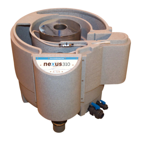
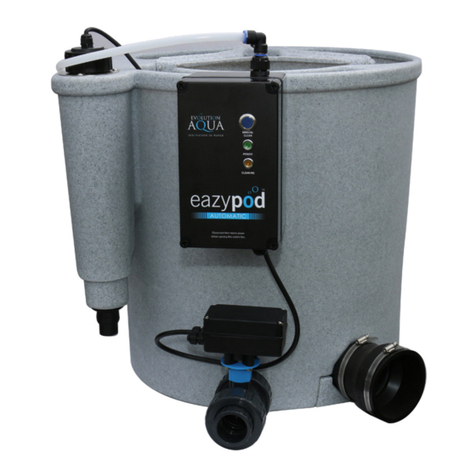
Evolution Aqua eazypod complete User manual

Evolution Aqua

Evolution Aqua eazypod complete User manual

Evolution Aqua NExus 300 User manual

Evolution Aqua

Evolution Aqua NExus 300 User manual

Evolution Aqua Cetus sieve Quick guide
Evolution Aqua

Evolution Aqua Cetus sieve Quick guide

Evolution Aqua NExus 300 Manual

Evolution Aqua

Evolution Aqua NExus 300 Manual

Evolution Aqua nexus 310 Quick guide

Evolution Aqua

Evolution Aqua nexus 310 Quick guide

Evolution Aqua Cetus sieve User manual

Evolution Aqua

Evolution Aqua Cetus sieve User manual

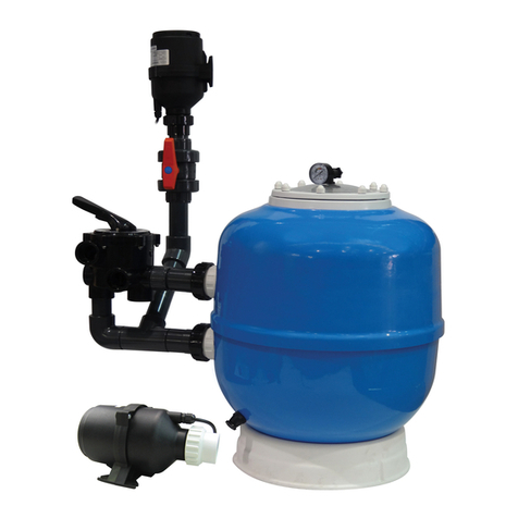
Evolution Aqua K1 MICRO BEAD 20 Quick guide

Evolution Aqua

Evolution Aqua K1 MICRO BEAD 20 Quick guide

Evolution Aqua evo15 User manual

Evolution Aqua

Evolution Aqua evo15 User manual

Evolution Aqua Nexus Eazy 200 Quick guide

Evolution Aqua

Evolution Aqua Nexus Eazy 200 Quick guide

Evolution Aqua eazypod Manual

Evolution Aqua

Evolution Aqua eazypod Manual

Evolution Aqua Nexus Eazy 200 Manual

Evolution Aqua

Evolution Aqua Nexus Eazy 200 Manual

Evolution Aqua eazypod Manual

Evolution Aqua

Evolution Aqua eazypod Manual

Evolution Aqua Nexus Eazy 200 Manual

Evolution Aqua

Evolution Aqua Nexus Eazy 200 Manual

Evolution Aqua PURE POND 5,000 Instruction Manual

Evolution Aqua

Evolution Aqua PURE POND 5,000 Instruction Manual

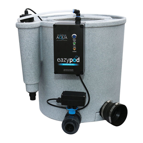
Evolution Aqua EAZYPOD AUTOMATIC Quick guide

Evolution Aqua

Evolution Aqua EAZYPOD AUTOMATIC Quick guide

Evolution Aqua Nexus Series Quick guide

Evolution Aqua

Evolution Aqua Nexus Series Quick guide

Evolution Aqua eazypod Quick guide

Evolution Aqua

Evolution Aqua eazypod Quick guide
Evolution Aqua eazypod Manual

Evolution Aqua

Evolution Aqua eazypod Manual

Evolution Aqua evoUV Series User manual

Evolution Aqua

Evolution Aqua evoUV Series User manual

Popular Water Filtration System manuals by other brands

Doughboy Sequel II 0-1651-000 owner's guide

Doughboy

Doughboy Sequel II 0-1651-000 owner's guide

EQUATION FS1 SL10 instruction manual

EQUATION

EQUATION FS1 SL10 instruction manual

Honeywell F74CS installation instructions

Honeywell

Honeywell F74CS installation instructions

Plumbline PD1000C owner's manual

Plumbline

Plumbline PD1000C owner's manual

Pentair 1.0 Service manual

Pentair

Pentair 1.0 Service manual

ATS DWS-8C Installation & operation manual

ATS

ATS DWS-8C Installation & operation manual

WaterStep M-100 instruction manual

WaterStep

WaterStep M-100 instruction manual

AquaticLife 540565 Installation, operation, maintenance guide

AquaticLife

AquaticLife 540565 Installation, operation, maintenance guide

CALEFFI 5790 Series Installation and commissioning manual

CALEFFI

CALEFFI 5790 Series Installation and commissioning manual

EcoFast EF500-DC Installation and operating instructions

EcoFast

EcoFast EF500-DC Installation and operating instructions

Watts Premier WP-4 BVC Installation, operation and maintanance manual

Watts Premier

Watts Premier WP-4 BVC Installation, operation and maintanance manual

STF-Filtros FMA-3000 Installation, operation and maintenance manual

STF-Filtros

STF-Filtros FMA-3000 Installation, operation and maintenance manual

SteriPEN Classic 3 user guide

SteriPEN

SteriPEN Classic 3 user guide

amiad EBS 769 Installation, operation and maintenance instructions

amiad

amiad EBS 769 Installation, operation and maintenance instructions

Culligan US-EZ Installation and operating instructions

Culligan

Culligan US-EZ Installation and operating instructions

EcoTAC Protector 4 Owner's manual & installation guide

EcoTAC

EcoTAC Protector 4 Owner's manual & installation guide

Wallace & Tiernan SERIES V-2000 manual

Wallace & Tiernan

Wallace & Tiernan SERIES V-2000 manual

Blichmann BeerGun Assembly operation maintenance

Blichmann

Blichmann BeerGun Assembly operation maintenance

manuals.online logo
manuals.online logoBrands
  • About & Mission
  • Contact us
  • Privacy Policy
  • Terms and Conditions

Copyright 2025 Manuals.Online. All Rights Reserved.