manuals.online logo
Brands
  1. Home
  2. •
  3. Brands
  4. •
  5. Sentinel
  6. •
  7. Controllers
  8. •
  9. Sentinel CPPM-4i User manual

Sentinel CPPM-4i User manual

SANTA ROSA, CALIFORNIA
CPPM-4i
|
CO2 PPM Controller Intelligent
©2015 Sentinel Global Product Solutions Inc. All rights reserved.
Distributed by Sentinel Global Product Solutions Inc., Santa Rosa, CA 95403
Sentinel GPS Inc. is dedicated to producing environmentally
sustainable products. The enclosed product complies with
RoHS Directive (2002/95/EC) that restricts the use of 6
hazardous substances such as mercury, cadmium and lead.
3 YEAR LIMITED WARRANTY
Sentinel Global Product Solutions Inc doing business as Sentinel, Sentinel Technologies, Global Product Solutions (collectively
SGPS) warrants that for a period of three years from the date of purchase, this product will be free from defects in material and
workmanship. SGPS, at its option, will repair or replace this product or any component of the product found to be defective
during the warranty period. Replacement will be made with a new or remanufactured product or component. If the product is
no longer available, replacement may be made with a similar product of equal or greater value. This is your exclusive warranty.
DO NOT attempt to repair or adjust any electrical or mechanical malfunctions on this product. Doing so will void this warranty
and may cause serious injury/death/damage.
This warranty is valid for the original retail purchaser from the date of the initial retail purchase and is not transferable. Keep
the original sales receipt. Proof of purchase is required to obtain warranty performance. SGPS dealers, distributors, service
centers and retail outlets selling SGPS products do not have any right to alter, modify or in any way change the terms and
conditions of this warranty.
This warranty does not cover normal wear of parts or damage resulting from the following: negligent use or misuse of the
product, use on improper voltage or current, use contrary to the operating instructions, use contrary to any and all applicable
local, state, provincial or federal laws, disassembly, repair or alteration by anyone other than SGPS or an SGPS authorized
service center. Further, the warranty does not cover: Acts of God, such as fire, flood, hurricanes, tornadoes; nor Acts of War
or Acts of Terrorism.
What are the limits on SGPS’s liability?
SGPS shall not be liable for any incidental or consequential damages cause by the breach of any express, implied or statutory
warranty or condition.
Except to the extent prohibited by applicable law, any implied warranty or condition of merchantability or fitness for a
particular purpose is limited in duration to the duration of the above warranty.
SGPS disclaims all other warranties, conditions or representations, express, implied, statutory or otherwise.
SGPS shall not be liable for any damages of any kind resulting from the purchase, use or misuse of, or inability to use the
product including incidental, special, consequential or similar damages or losses of profits, or for any breach of contract,
fundamental or otherwise, or for any claim brought against the purchaser by any other party.
Some provinces, states or jurisdictions do not allow exclusion or limitation of incidental or consequential damages or
limitations on how long an implied warranty lasts, so the above limitations or exclusion may not apply to you.
This warranty gives you specific legal rights, and you may also have other rights that vary from province to province, state to
state or jurisdiction to jurisdiction.
In the USA and Canada, this warranty is offered by Sentinel Global Product Solutions Inc. If you have any other problem or
claim in connection with this product, please write our Consumer Service Headquarters:
Sentinel GPS, 422 Larkfield Center PMB 281, Santa Rosa, CA 95403 USA.
Please do not return this product to this address, as the product will be refused for delivery.
2 3
• Neverexceedrecommendedamperage
• Verifypowersourcepriortoconnectingunittopowersource
• Makesureunitissecurelymounted
• Donotmountunitnearheatgeneratingsources
• Thisunitshallnotbeexposedtodripping,splashingorsprayingofliquids.
Protect unit from vapors, foggers etc.
• Cleanunitwithcleandrycloth,nooilsorsolvents.
• Protectanypowercordsfrombeingwalkedon,pinchedorcrushed.
• Unitisdesignedforindooruseonly
• Unitistobeusedwithindefinedenvironmentalparameters
• Usecautionwhenoperatinginhighhumidityenvironments
• Thisunitcontainsnouser-serviceableparts.Donotattempttoservice
this product.
• Verifythatallequipmentconnectedtounitisofpropervoltage
• Donotputpaperclips,toolsetcinsideunitopeningsorreceptacles.
Possible fire, shock or death may occur.
IMPORTANT: The remote probe contains sensitive electronic componentry.
Protect from spraying, splashing, misting, foggers, sulfur vapors, pesticides,
fungicides, cleaning solutions. Probe assembly should be covered or removed
prior if the possibility of any of these occurring exists. Damage from these
occurrences is NOT covered under warranty.
Protect probe from impacts and jarring.
Any damage to probe will be considered improper usage or user neglect and
void any and all warranties.
IMPORTANT WARNINGS AND CAUTIONS
Read all instructions before installation and usage.
Save these instructions.
GETTING TO KNOW YOUR CPPM-4i
CO2 DEVICE
RECEPTACLE
LED STATUS
DISPLAY
BATTERY COMPARTMENT
REMOTE
SENSOR
CONNECTION
ON/OFF
SWITCH
FUSE HOLDER
COMPARTMENT
TYPE (250V /
5A F3AL250V)
Scan this code to
learn more about
the Sentinel
CPPM-4i on your
smart phone!
SENTINEL
S.I.C.E. CO2
GENERATOR
CONNECTION
4 5
1. Open battery compartment located on bottom of unit. Remove the plastic protection
tab from underneath the battery. Replace battery compartment cover
2. Mount supplied bracket to wall
3. Slide unit onto bracket
4. Secure unit to bracket with supplied set screws
5. Connect one end of supplied S.I.C.E. shielded communications cable to unit.
Route cable as needed. Connect other end of S.I.C.E. cable to the remote sensor
in the desired location.
6. Make sure power switch is in the “OFF” position. Connect power cable to unit.
7. Plug power cable into appropriate receptacle. A timer or other device should not be used.
8. Turn power switch to the “ON” position
9. Uponinitialpowerup,andsubsequentre-starts,theunitwilltake2-5minutesto
warm up, stabilize the CO2 sensor and begin operation. This is normal.
10. Set the current time. This is done by pressing and holding the “Set Clock” button for
5 seconds. Make sure to press the enter button after every value to save the settings
into memory.
11. Set the CO2 on / off time. This is done by pressing the “CO2 ON/OFF TIME” button.
The CO2 ON time should coincide with the lights ON cycle or daytime. The CO2 OFF
time should coincide with the lights OFF cycle or night time. Make sure to press the
enter button after every value to save the settings into memory.
For 24 hour ON light cycles, set the CO2 ON AND OFF times to 10:00 and 10:00. This
will allow for continuous CO2 control and enrichment.
INITIAL INSTALLATION INSTRUCTIONS
S.I.C.E. shielded communications cables are available from your preferred retailer,
or from www.growgps.com/store Sentinel S.I.C.E shielded communications
cables are available in 5 meter (part# SICEcbl5), 10 meter (part# SICEcbl10),
25 meter (part# SICEcbl25), and 50 meter (part# SICEcbl50) lengths.
These are NOT standard Ethernet cables. They are shielded to reduce interference
coming from digital ballasts, and are specially coated to not allow moisture
inside. The use of standard Ethernet cables in NOT recommended, and any harm
that comes from the use of non-Sentinel approved cables VOIDS any and all
warranties. The special coatings on these cables makes them less-flexible
than standard Ethernet cables. They are not intended to be highly flexible. It is
recommended after installation that the cables are affixed securely to the walls
or ceilings of your greenhouse or grow room in a manner that makes sure the
cables are not pinched or crushed.
While every effort has been made to shield your CPPM-4i from EMI (Electromag-
netic Interference) it is still not recommended to place your CPPM-4i main unit,
probes and cables to close to electronic or digital ballasts. It is not recommended
to run the S.I.C.E. cables in electrical raceways with digital ballast lamp
cords.
TIP:
YournewSentinelCPPM-4iisthemostadvancedCO2controlleravailableonthemarket
today. It incorporates the proprietary S.I.C.E. – Sentinel Intelligent CO2 Enrichment –
communication and control components and programming that are unique to Sentinel.
This patent pending system allows for communications between Sentinel S.I.C.E series
products, providing a level of control never before seen in your greenhouse, garden or
grow room.
ThesystemworksbyaSentinelS.I.C.E.seriescontroller,suchastheSentinelCPPM-4i,
measuring and monitoring your growing environment. As the atmospheric CO2 levels
change, the controller will tell the ICG series generator to increase output, decrease output,
or go into idle mode…all computer controlled. In this way, a growing environment that
has very low CO2 levels, such as the start of the day or after a ventilation cycle, can be
rapidly brought back up to optimal growing conditions. As the optimal conditions are
reached, the S.I.C.E. system can decrease CO2 output, making sure that the user defined
optimal level is not overshot. As needed, the growing environment can be “topped off”
with CO2 enrichment on a lower output setting, allowing for air conditioners and
dehumidifiers to better deal with the heat and moisture loads associated with CO2
enrichment and maintaining more constant temperature and rH levels.
1. FollowinitialinstallationinstructionsforSentinelCPPM-4iandSentinelICG
Series generator.
2. ConnectCPPM-4itoICG-30withSentinelS.I.C.E.cableofappropriatelength.
(Cables available separately).
3. Set the desired CO2 levels for the S.I.C.E. control with the “Sentinel Intelligence”
button. Mode 1 is the “High” setting for the CO2 generator, meaning full output.
Mode 2 is the “Medium” setting for the CO2 generator, meaning 2/3rd output.
Mode 3 is the “Low” setting for the CO2 generator, meaning 1/3rd output. Make
sure to press the “Enter” button after each value.
It is important to note that since all growing areas are different, settings for the
S.I.C.E. control will have to be tailored to each environment for optimal function.
SENTINEL INTELLIGENT CO2 ENRICHMENT ( S.I.C.E.)
Some universities have suggested that CO2 levels be enriched 20-30 minutes
after lights have turned ON. This allows plant’s stomata to open and the plant
to begin respiration prior to CO2 enrichment. CO2 can also be turned OFF
20-30 minutes (even more) prior to the lights actually turning off. This allows
the garden to use up the elevated CO levels prior the dark period. Both of these
are possible with the Sentinel CPPM-4i. Individual greenhouses and gardens
will vary. Please proceed at your own risk/discretion.
6 7
WhiletheSentinelCPPM-4ihasbeendesignedwithadvancedcommunicationand
control componentry for ideal operation using the proprietary S.I.C.E. system, the
CPPM-4icanworkwithallcurrentandpreviousSentinelbrandCO2generatorsas
well as other manufacturer offerings. And the best part is you can always upgrade
to a Sentinel ICG series S.I.C.E. generator in the future!
1. FollowinitialinstallationinstructionsforyourSentinelCPPM-4iandforyour
SentinelVCGseriesgeneratororotherbrandCO2generator.
2. Set desired CO2 enrichment level with the “Set CO2 button”. Make sure to press
“Enter” after the desired level is set.
3. EnsuretheCPPM-4iissettoCO2GeneratorMode.Thisisaccomplishedbypressing
and holding the “Enter” button for 5 seconds. Using the Up/Down buttons put the
CPPM-4iinGeneratormode.PresstheENTERbuttontoconfirmyourselection.
4. Plug the power supply for the CO2 generator into the CO2 Device receptacle.
5. If you notice the CO2 levels are exceeding your set point, use a lower power setting
on the CO2 generator.
6. If you notice the CO2 generator cycling on and off too frequently, try increasing the
hysteresis using the “CO2 Hysteresis” button.
TheSentinelCPPM-4ihasbeendesignedwiththemostadvanced“TrueFuzzyLogic”
programming and componentry for optimal use with CO2 regulator / bottled CO2
pairings. While many CO2 brands claim to use fuzzy logic, they are really using a
less advance PID control loop design. Sentinel “True Fuzzy Logic” ensures the most
precise control and enrichment levels available to bottled CO2 regulator users.
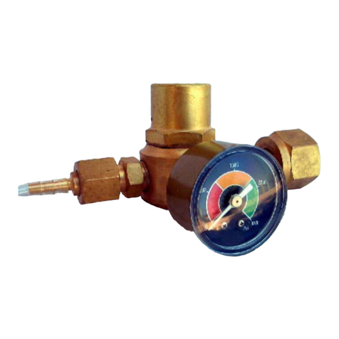
For best results, Sentinel recommends using the highest
quality Sentinel CO2-REG components.
1. FollowinitialinstallationinstructionsforSentinelCPPM-4iandSentinelCO2-REG
or other brand CO2 regulator.
2. Set desired CO2 enrichment level with the “Set CO2 button”. Make sure to press
“Enter” after the desired level is set.
3. MakesuretheCPPM-4iissetto“TrueFuzzyLogic”mode.Thisisaccomplishedby
pressing and holding the “Enter” button for 5 seconds. Using the Up/Down buttons,
puttheCPPM-4iinFuzzyLogicmode.Presstheenterbuttontoconfirmyourselection.
4. Plug the power supply for the CO2 regulator into the CO2 Device receptacle.
5. If you notice the CO2 levels are exceeding your set point, use a lower output
flowrate setting on the CO2 regulator.
Sentinel Standard CO2 Generator Function
Sentinel “True Fuzzy Logic” CO2 Operation for bottled CO2
Recalibration of the CO2 sensor:
Recalibration of CO2 sensor is required at 12 month intervals, after the probe being
jarred/sustaining rough handling, or other times if CO2 levels do not appear to be
reading accurately. Recalibration of the CO2 sensor is a fairly simple process,
provided that basic protocols are followed:
1. Move the remote sensor to an area outside of the garden or greenhouse that is in
freshair-preferablyoutdoors.Thesensormustbeawayfrompeopleandother
CO2 generation sources. Protect unit from direct sunlight.
2. TurnthepowerontotheCPPM-4i.Allowtheunittooperateundisturbedfora
minimum of 30 minutes with a time of 1+ hours being optimal.
3. Press the CO2 Calibrate button on the main controller. Set the desired ambient
(baseline) CO2 levels using the UP/DOWN arrows. Normally, this will be 400ppm.
In larger cities or more congested areas, settings up to 450ppm may be used.
Press the ENTER button to confirm your selection.
4. Leave the area and keep people or other CO2 generation sources away from the
unit for a minimum of 15 minutes.
5. ReturntheCPPM-4itoyourgardenorgreenhouse.
Annual Battery Replacement:
Forcontinuedoptimalperformance,itisrecommendedthatthebatteryfortheCPPM-4i
be replaced on an annual basis. Use of a high quality CR 2025 button cell battery is
required. Please follow proper local disposal procedures for your discarded battery.
GENERAL MAINTENANCE PROCEDURES
For optimal continued operation of your CPPM-4i,
several general maintenance procedures are required on a periodic basis.
THANK YOU
for choosing Sentinel!
In a world of compromises, we never!™
•••••••
For installation help, tips and tricks visit our YouTube channel
www.youtube.com/SentinelGPS

Other Sentinel Controllers manuals

Sentinel HPH-4 User manual

Sentinel

Sentinel HPH-4 User manual

Sentinel HID-1 User manual

Sentinel

Sentinel HID-1 User manual

Sentinel CO2-EXP User manual

Sentinel

Sentinel CO2-EXP User manual

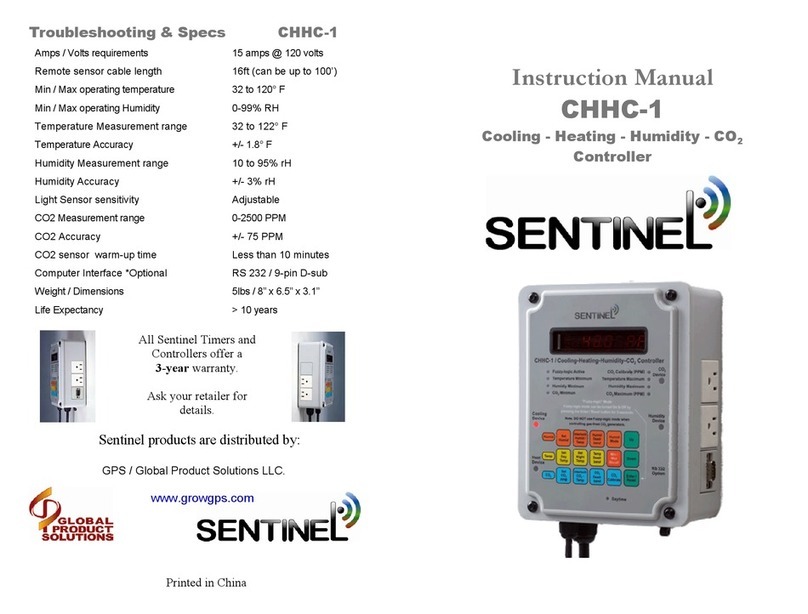
Sentinel CHHC-1 User manual

Sentinel

Sentinel CHHC-1 User manual

Sentinel EVC-2 User manual

Sentinel

Sentinel EVC-2 User manual

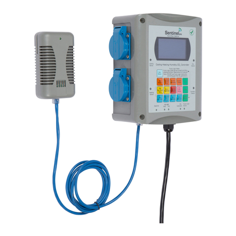
Sentinel CHHC-4i User manual

Sentinel

Sentinel CHHC-4i User manual

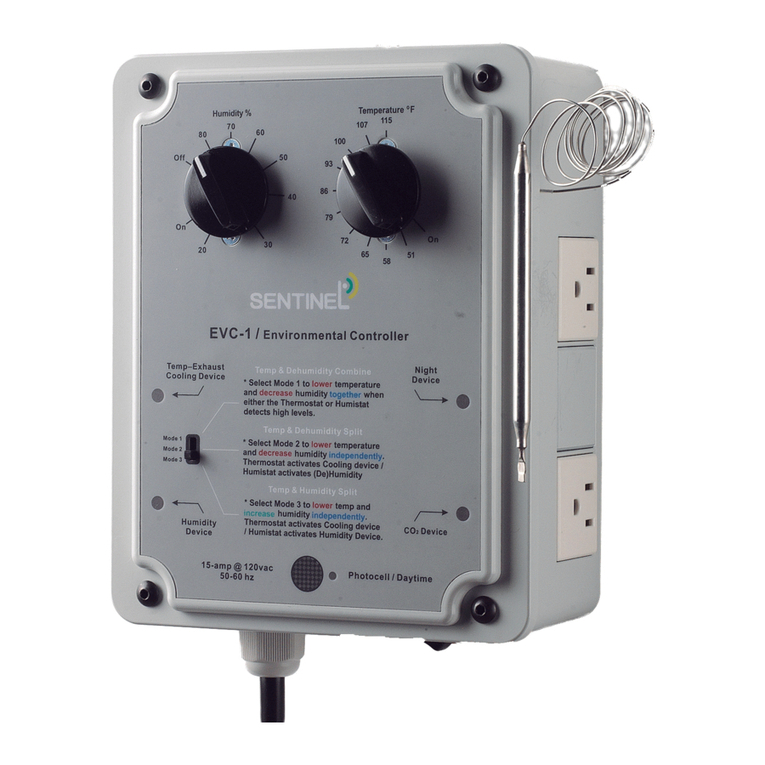
Sentinel EVC-1 User manual

Sentinel

Sentinel EVC-1 User manual

Popular Controllers manuals by other brands

Alemite 7504-1 Installation and service instructions

Alemite

Alemite 7504-1 Installation and service instructions

impact CE400 manual

impact

impact CE400 manual

Linear Technology LTM4650-1 Demo Manual

Linear Technology

Linear Technology LTM4650-1 Demo Manual

Analog Devices DC3126A Demo Manual

Analog Devices

Analog Devices DC3126A Demo Manual

Linear Technology LTC7103 Demo Manual

Linear Technology

Linear Technology LTC7103 Demo Manual

KRUEGER CRFF Installation operation & maintenance

KRUEGER

KRUEGER CRFF Installation operation & maintenance

Danfoss MCI 15BP instructions

Danfoss

Danfoss MCI 15BP instructions

Danfoss ECL Comfort 310 installation guide

Danfoss

Danfoss ECL Comfort 310 installation guide

REMKO RR 22.0 Operation  Technology

REMKO

REMKO RR 22.0 Operation Technology

TURY FAST 3.0 installation guide

TURY

TURY FAST 3.0 installation guide

AUMA TIGRON TR-M30X Operation instructions

AUMA

AUMA TIGRON TR-M30X Operation instructions

Renogy ROVER Series Installation and operation manual

Renogy

Renogy ROVER Series Installation and operation manual

RCmart ESC 45A-H Quick start quide

RCmart

RCmart ESC 45A-H Quick start quide

AMX KCR Dimensional drawing

AMX

AMX KCR Dimensional drawing

Omron SCC-1224 Installation and operating manual

Omron

Omron SCC-1224 Installation and operating manual

rotork centork CK Series Startup guide

rotork

rotork centork CK Series Startup guide

Bamo CNL user manual

Bamo

Bamo CNL user manual

EuroLite 52202222 user manual

EuroLite

EuroLite 52202222 user manual

manuals.online logo
manuals.online logoBrands
  • About & Mission
  • Contact us
  • Privacy Policy
  • Terms and Conditions

Copyright 2025 Manuals.Online. All Rights Reserved.