manuals.online logo
Brands
  1. Home
  2. •
  3. Brands
  4. •
  5. senva
  6. •
  7. Accessories
  8. •
  9. senva CHTWL Series User manual

senva CHTWL Series User manual

INSTALLATION INSTRUCTIONS
senvainc.com 1-866-660-8864 (F)1-503-296-2529 9290 SW Nimbus Ave. Beaverton Oregon 97008
CHTWL Series
Room CO2/RH/T combo sensor
PRODUCT APPLICATION LIMITATION:
Senva products are not designed for life or safety applications. Senva products
are not intended for use in critical applications such as nuclear facilities, human
implantable device or life support. Senva is not liable, in whole or in part, for
any claims or damages arising from such uses.
INSTALLATION (CONTINUED)
kWire sensor according to the product labeling.
lInstall sensor to wall or j-box using screws provided.
mMove jumper to select 5v or 10v.
IMPORTANT WARNINGS
• Only qualied trade installers should install this product
• This product is not intended for life-safety applications
• Do not install in hazardous or classied locations
• The installer is responsible for all applicable codes
• De-energize power supply prior to installation or service
INSTALLATION
jIMPORTANT! Locate sensor in an area away from ventillation
sources and heat generating equipment and appliances.
Sensor should be mounted at light switch height in a vertical
orientation. Use insulating material behind sensor to ensure
reading accuracy.
NOTE: Do not install sensor in multi-gang electrical boxes with
line voltage or other electrical devices.
COMPUTER
ROOM
OUTSIDE
WALL OR WINDOW
TOO HOT/COLD
INSIDE WALL
TOO HOT/COLD
COPIER
TOO NEAR
EQUIPMENT OR DOORWAY
GOOD
LOCATION
GOOD
LOCATION
GOOD
LOCATION
nApply power to sensor to complete optional setup
functions:
HOLD qANDpFOR 5-SECONDS TO ENTER SETUP MENU.
PRESS qOR p TO CHOOSE PARAMETER TO ADJUST.
SPH Setpoint, Hi (Closed above this level)
SPL Setpoint, Lo (Open below this level)
SCL Scaling “2” = 2000ppm, “5” = 5000ppm
ADJ Manual calibration adjustment +/-250ppm
CAL Automatic calibration - ON/OFF/RST (reset)
FoC Temperature units oF or oC
RUN Exit setup mode - display actual CO2 ppm
PRESS SELECT TO EDIT SELECTED PARAMETER
PRESS qOR p TO CHANGE VALUE
PRESS SELECT TO RETURN TO PARAMETER MENU
WHEN SETUP IS COMPLETE, SELECT RUN, OR WAIT FOR SETUP
MODE TO AUTOMATICALLY TIME-OUT AND REVERT TO RUN
MODE.
oInstall cover to back plate by engaging hinge at top rst,
then gently rocking bottom end closed. Optionally secure with
screw provided. Snap in desired bezel to conceal or reveal LCD.
PPM
1 0 0 0
REPLACEABLE
CO2 SENSOR
MODULE
OUT RH
OUT T
OUT CO2
CO2 RELAY
CO2 RELAY
GND/COMMON
POWER VIN
TH
TH
MAX
WIPER
MIN
THERMISTOR/
OVERRIDE
(OPTION)
V
SLIDE POT
(OPTION)
SEL
TO ENTER SETUP MODE:
HOLD AND 5-SEC


+
SETPOINT
RELAY


0-10V
0-5V
RH/T SENSOR
V
SPECIFICATIONS
TROUBLESHOOTING
Symptom Solution
No output Check wiring. Ensure power supply
meets requirements.
Reading error Verify unit is located away from
hot/cold sources.
Power supply 12-30vdc/24vac (1), 100mA max.
Outputs Voltage Only 3-wire 0-5v/0-10v (2) (jumper)
CO2
Type Non-dispersive Infrared (NDIR)
Accuracy +/-40ppm, +/-3% of reading
Response time 60 seconds to 90% reading
Update rate 3 seconds
Output scaling 0-2000ppm (default), 0-5000ppm (option)
Programmable set-point output Solid-state, 1A@30VAC/DC, N.O.
Relative Humidity
Accuracy 2% models, +/-2% over 10 to 90% range
3% models, +/-3% over 20 to 80% range
Resolution 0.05%RH
Hysteresis +/-1%RH
Non-linearity Factory linearized <1%RH
Temperature coecient Fully compensated by on-board sensor
Response time (3) 30s
Output update rate 2s
Operating range 0 to 100%RH (non-condensing)
Long term drift <0.5%RH per year
Operating conditions (4) -20 to 60oC @ RH >90%
-20 to 80oC @ RH = 50%
Temperature (Transmitter)
Scaling 50 to 95oF (10-35oC)
Accuracy, (-20 to 70oC range) 2% models, <+/-1oC; 0.5oC typ@25oC
3% models, <+/-2oC; 0.5oC typ@25oC
Resolution 0.01oC
Repeatability +/-0.1oC
Response time (2) 30s
Output update rate 2s
Operating range -40 to 120oC (sensor only)
Operating Environment Temperature 32 to 122oF (0-50oC)
Humidity 0-95%RH, non-condensing
Enclosure Material ABS Plastic
Dimensions 4.85”h x 3.25”w x 1.19”d
Automatic CO2 Calibration feature:
When CAL mode is set to ON, the sensor will automatically track low ambient CO2 levels and gradually make adjustments to
compensate for sensor drift due to long-term aging of the IR light source. In applications where CO2 levels are continuously
elevated, or spaces are occupied day and night, it is recommended to leave the automatic calibration OFF. If the sensor module is
replaced in the eld, the automatic adjustments can be reset by selecting the RST (reset) option in the CAL menu.
(1) One side of transformer secondary is connected to signal common. Dedicated transformer is recommended.
(2) 15-30vdc/24vac power supply voltage required for 10 volt output.
(3) Time for reaching 63% of reading at 25oC and 1 m/s airow.
(4) Long term exposures to conditions outside normal range or high humidity may temprarily oset the RH reading (+3%RH after 60 hours.)
Symptom Solution
Reading error
Verify control panel software is
congured for correctly.
Verify accuracy of test instrument.
Install insulation behind sensor to
prevent air ow from inside wall.
Revised 7/3/2014 Document #152-0110-0A
Other senva Accessories manuals

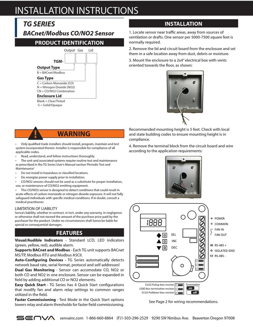
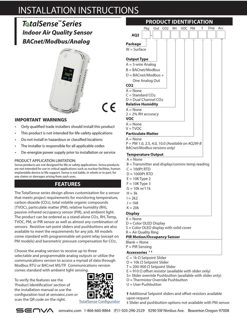
senva TotalSense Series User manual

senva

senva TotalSense Series User manual

senva TotalSense Series User manual

senva

senva TotalSense Series User manual

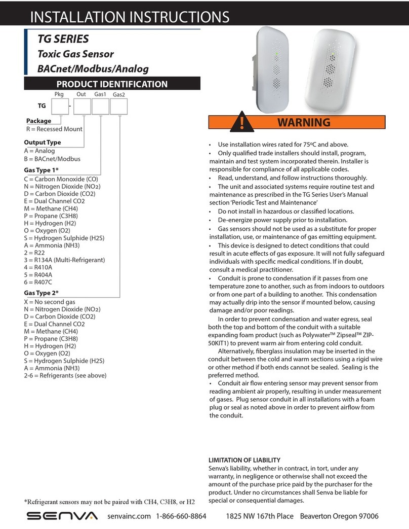
senva TG Series User manual

senva

senva TG Series User manual

senva AQ Series User manual

senva

senva AQ Series User manual

senva TG Series User manual

senva

senva TG Series User manual

senva TotalSense Series User manual

senva

senva TotalSense Series User manual

senva TG Series User manual

senva

senva TG Series User manual

senva TG Series User manual

senva

senva TG Series User manual

senva TG Series Installation and operating instructions

senva

senva TG Series Installation and operating instructions

senva TG Series User manual

senva

senva TG Series User manual

senva TG Series User manual

senva

senva TG Series User manual

Popular Accessories manuals by other brands

Quincy lab 140AE-1 operating manual

Quincy lab

Quincy lab 140AE-1 operating manual

HomePro ZIR000 user manual

HomePro

HomePro ZIR000 user manual

DOL 20SCR Technical user guide

DOL

DOL 20SCR Technical user guide

RAB Smart Task installation manual

RAB

RAB Smart Task installation manual

Kemppi KMS 300 quick guide

Kemppi

Kemppi KMS 300 quick guide

Stearns 57,500 Series Installation and service instructions

Stearns

Stearns 57,500 Series Installation and service instructions

iGuzzini TWILIGHT COPENAGHEN manual

iGuzzini

iGuzzini TWILIGHT COPENAGHEN manual

Adelaide Annexe & Canvas Avan Deluxe installation guide

Adelaide Annexe & Canvas

Adelaide Annexe & Canvas Avan Deluxe installation guide

OHAUS 5000 instruction manual

OHAUS

OHAUS 5000 instruction manual

HOME8 WLS1300 quick start guide

HOME8

HOME8 WLS1300 quick start guide

MAXBOTIX MaxSonar quick start guide

MAXBOTIX

MAXBOTIX MaxSonar quick start guide

ioSmart iSmart56 Installation and user guide

ioSmart

ioSmart iSmart56 Installation and user guide

Focusrite Scarlett 18i8 user guide

Focusrite

Focusrite Scarlett 18i8 user guide

Velleman ED38105 user manual

Velleman

Velleman ED38105 user manual

JumpSport SkyBounce user manual

JumpSport

JumpSport SkyBounce user manual

Prima-Temp PRIYA Instructions for use

Prima-Temp

Prima-Temp PRIYA Instructions for use

Tefcold BC85I-BC85I W user manual

Tefcold

Tefcold BC85I-BC85I W user manual

Vaisala WMS302 user guide

Vaisala

Vaisala WMS302 user guide

manuals.online logo
manuals.online logoBrands
  • About & Mission
  • Contact us
  • Privacy Policy
  • Terms and Conditions

Copyright 2025 Manuals.Online. All Rights Reserved.