senva TG Series User manual

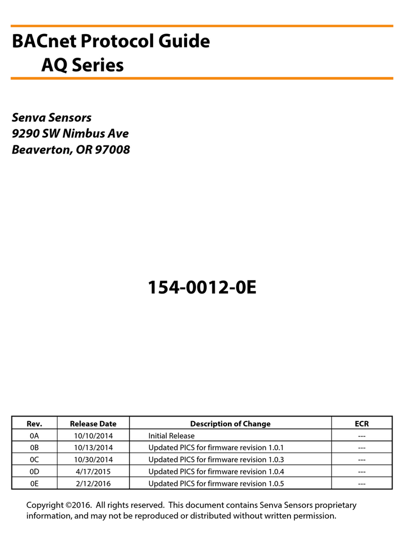
User’s Guide
TG Series
Senva Sensors
9290 SW Nimbus Ave
Beaverton, OR 97008
154-0031-0C
Rev. Release Date By Description of Change ECR
0A
4/14/2016
CKB
Initial Release
---
0B
3/7/2017
CKB
Updated for RS485 version.
---
0C
9/12/2017
CKB
Added “Periodic Test and Maintenance” section
---
Copyright ©2017. All rights reserved. This document contains Senva Sensors proprietary
information, and may not be reproduced or distributed without written permission.

User’s Guide, TG Series Page 2 of 17 154-0031-0C
Contents
General Overview.................................................................................................................................................................................... 3
User Menu .................................................................................................................................................................................................. 4
................................................................................................................................................................................................ 5
/ .................................................................................................................................................................................. 5
................................................................................................................................................................................................... 7
................................................................................................................................................................................... 8
................................................................................................................................................................................. 9
...............................................................................................................................................................................10
......................................................................................................................................................................................10
......................................................................................................................................................................................11
..............................................................................................................................................................................................11
...........................................................................................................................................................................................12
Setup Menu..............................................................................................................................................................................................13
........................................................................................................................................................................................................13
......................................................................................................................................................................................................14
Testing Menu ..........................................................................................................................................................................................15
Idle Condition Codes............................................................................................................................................................................16
Periodic Test and Maintenance........................................................................................................................................................17
References:
152-0270 TG Series Analog Installation Instructions
152-0271 TG Series RS485 Installation Instructions
152-0272 TG Series Hose Barb Installation Instructions
152-0273 TG Sensor Replacement Instructions
154-0032 BACnet Protocol Guide
154-0033 Modbus Protocol Guide

User’s Guide, TG Series Page 3 of 17 154-0031-0C
General Overview
The TG product contains 3 menu systems:
•User Menu – Configure system functions setpoints, such as relay setpoints and analog output
scaling.
•Setup Menu – Add/Remove sensors, and view sensor information.
•Testing Menu – Test functionality of system interfaces, such as relays and analog output signals.
Each menu is composed of a hierarchy of primitive elements: Categories, Items, Numerical Values, and Option
Values. Categories give you access to Items, which may contain either Numerical Values when the setting is
numerical, or Option Values when the setting is multiple choice. A list of available Categories is shown at the
top of each menu in this document. See Figure 1 below for an example.
Default
0-10V
Quickstart
User Menu
0-5V 4-20mA 1-5V
A
Menu Category Item Option Values
.
..
.
0-120
(minutes)
Fan Relay
Min
On
Time
Numerical Value
Item
Figure 1: The “Quickstart” category contains an Item ‘A’, which has a set of multiple choice option values. The
“Fan Relay” category has an Item ‘Min On Time’ (
) which can be set to any Numerical Value between 0-120 in
minutes.
Buttons
•◆– “Select” button.
•▲– “Inc” button (Increment).
•▼– “Dec” button (Decrement).
Navigation and Selection
•Pressing ▲or ▼while viewing a Category/Item advances to the next or previous Category/Item.
•Pressing ▲or ▼while viewing a Numerical Value increments or decrements the value.
•Pressing ▲or ▼while viewing an Option Value scrolls through the available options.
•Pressing ◆while viewing a Category allows you to view the items it contains.
•Pressing ◆while viewing an Item allows you to view and modify the Values/Options for that Item.
•Pressing ◆while viewing a Value/Option applies your selection and returns you to the Item view.
•Hold ▲, ▼, and ◆for 1 second while the alarm buzzer is active to suppress the alarm.
•Each Menu contains an
Item, which will exit the current menu.
•Each Category contains an
Item, which will return you to the previous Menu screen.
*Unless otherwise specified, all changes to Numerical Values/Option Values occur at the time
▲
or
▼
is pressed.
SEL
INC
DEC

User’s Guide, TG Series Page 4 of 17 154-0031-0C
User Menu
Access the User Menu by pressing the ◆button for one second.The User Menu organizes settings into
several categories. Many of these settings can also be modified over BACnet or Modbus. The
object/instance number is noted in each modifiable value. See the relevant protocol guide for more
information.
Categories
•Quickstart (
)
Allows the user to select from a list of pre-defined configurations for quick and easy startup.
•Analog Output Channel 1 (
)
Contains all of the settings which control the output signal on channel 1. (Analog Version only)
•Analog Output Channel 2 (
)
Contains all of the settings which control the output signal on channel 2. (Analog Version only)
•RS485 (
)
Manually set the RS485 communication settings. (RS485 Version only)
•CO Setpoints (
)
Contains all of the user configurable setpoints, which control the system response to the CO Gas Sensor.
(CO Sensor only)
•NO2Setpoints (
)
Contains all of the user configurable setpoints, which control the system response to the NO2 Gas
Sensor. (NO2Sensor only)
•Temperature Setpoints (
)
Contains all of the user configurable setpoints, as well as unit selection, which control the system
response to the thermistor.
•Fan Relay (
)
Configure the timing of the fan relay (warning relay).
•Alarm Relay (
)
Configure the timing of the alarm relay. (Analog Version only)
•Buzzer (
)
Configure the timing of the alarm buzzer.
•Display (
)
Customize the performance of the display.

User’s Guide, TG Series Page 5 of 17 154-0031-0C
Applies the following setpoints to their respective sensors:
CO Warning = 25, CO Alarm = 100, NO2 Warning = 1, NO2 Alarm = 3 (in PPM), Buzzer Delay = 30 (minutes).
0-10V Output Range (Default)
1-5V Output Range (Analog Version Only)
4-20mA Output Range (Analog Version Only)
0-5V Output Range (Analog Version Only)
Applies the following setpoints to their respective sensors:
CO Warning = 15, CO Alarm = 50, NO2 Warning = 0.7, NO2 Alarm = 2 (in PPM), Buzzer Delay = 30 (minutes).
0-10V Output Range
1-5V Output Range (Analog Version Only)
4-20mA Output Range (Analog Version Only)
0-5V Output Range (Analog Version Only)
Applies the following setpoints to their respective sensors:
CO Warning = 35, CO Alarm = 100, NO2 Warning = 1, NO2 Alarm = 5 (in PPM) , Buzzer Delay = 30 (minutes).
0-10V Output Range
1-5V Output Range (Analog Version Only)
4-20mA Output Range (Analog Version Only)
0-5V Output Range (Analog Version Only)
Applies the following setpoints to their respective sensors:
CO Warning = 5, CO Alarm = 10, NO2 Warning = 0.5, NO2 Alarm = 1 (in PPM) , Buzzer Delay = 2 (minutes).
0-10V Output Range
1-5V Output Range (Analog Version Only)
4-20mA Output Range (Analog Version Only)
0-5V Output Range (Analog Version Only)
Returns to the User Menu screen.
/
Selects the output mode of the analog output signals. Changing this setting on either
or sets the output mode on both analog output channels.
Voltage Out (Default)
Current Out

User’s Guide, TG Series Page 6 of 17 154-0031-0C
Selects the sensor to be output on output channel 1 () or output channel 2 (). By
default, if a single sensor is present it will be configured on output channel 1. If two sensors are
present, CO will default to output channel 1, while the NO2 sensor will default to output
channel 2.
No sensor selected.
CO Gas.
NO2 Gas.
Temperature.
Sets the voltage corresponding to the maximum sensor reading, 0-10 Volts.
Default: Volts
Sets the voltage corresponding to the minimum sensor reading, 0-10 Volts.
Default: Volts
Sets the current corresponding to the maximum sensor reading, 4-20 Milliamps.
Default: Milliamps
Sets the current corresponding to the minimum sensor reading, 4-20 Milliamps.
Default: Milliamps
Returns to the User Menu screen.

User’s Guide, TG Series Page 7 of 17 154-0031-0C
Sets the RS485 address. The full address range 0-254 is supported. When at address 255, this is
considered “AUTO ADDRESSING” mode (see TG BACnet/Modbus Protocol Guides), and will show
up as ““ on the LCD display if an automatic address has not been detected and configured.
Once an address has been selected in auto mode, the address will show up in this field along
with an “O/R” symbol in the bottom center of the LCD to indicate this address was
automatically selected by the TG.
RS485 Version Only: AV123 (BACnet), R123 (Modbus).
Default: (Auto Mode)
Sets the Ones digit of the device id. The max device id is 4,194,302
If the combination of id.1 and id.2 exceed 194,302, then the max value that may be set it the
id.3 field is 3.
Example: To set the device id to 1,234,567 each id field should be as follows 1
.3
234
.2
567
.1
Default: Varies
Sets the Thousands digit of the device id. See .
Default: 665
Sets the Millions digit of the device id. See .
Default: 0
Sets the RS485 baud rate.
RS485 Version Only: AV124 (BACnet), R124 (Modbus).
Auto Baud Rate (Default)
9600 Baud
19,200 Baud
28,800 Baud
38,400 Baud
57,600 Baud
76,800 Baud
115,200 Baud
230,400 Baud
460,800 Baud
Sets the RS485 protocol.
RS485 Version Only: MSV122 (BACnet), R122 (Modbus).
Auto Protocol (Default)
BACnet
Modbus ASCII
Modbus RTU

User’s Guide, TG Series Page 8 of 17 154-0031-0C
Sets the RS485 parity.
RS485 Version Only: MSV126 (BACnet), R126 (Modbus).
Auto Parity (Default)
No Parity
Odd Parity
Even Parity
Sets the RS485 data bits.
RS485 Version Only: R127 (Modbus accessible only).
Auto Data Bits (Default)
7 Data Bits
8 Data Bits
Sets the RS485 stop bits.
RS485 Version Only: R128 (Modbus accessible only).
Auto Stop Bits (Default)
Stop Bit
1.5 Stop Bits
2 Stop Bits
Returns to the User Menu screen.
Sets the alarm setpoint level in PPM. Accepts any value between 0-1000 in whole PPM.
RS485 Version Only: AV152 (BACnet), R152 (Modbus).
Default: PPM
Sets the warning setpoint level in PPM. Accepts any value between 0-1000 in whole PPM.
RS485 Version Only: AV150 (BACnet), R150 (Modbus).
Default: PPM
Sets the setpoint hysteresis, in PPM. The setpoint hysteresis defines how far below the
Warning/Alarm setpoint the sensor value must drop before changing state from Alarm to
Warning or Warning to Normal.
RS485 Version Only: AV154 (BACnet), R154 (Modbus).
Default: PPM

User’s Guide, TG Series Page 9 of 17 154-0031-0C
Sets the value in PPM which corresponds to the maximum analog output signal range. Accepts
any value between 0-1000 in whole PPM. (Analog Version Only)
Default: PPM
Sets the value in PPM which corresponds to the minimum analog output signal range. Accepts
any value between 0-1000 in whole PPM. (Analog Version Only)
Default: PPM
Returns to the User Menu screen.
Sets the alarm setpoint level in PPM. Accepts any value between 0-20 in whole PPM.
RS485 Version Only: AV162 (BACnet), R162 (Modbus).
Default: PPM
Sets the warning setpoint level in PPM. Accepts any value between 0-20 in whole PPM.
RS485 Version Only: AV160 (BACnet), R160 (Modbus).
Default: PPM
Sets the setpoint hysteresis, in PPM. The setpoint hysteresis defines how far below the
Warning/Alarm setpoint the sensor value must drop before changing state from Alarm to
Warning or Warning to Normal.
RS485 Version Only: AV164 (BACnet), R164 (Modbus).
Default: PPM
Sets the value in PPM which corresponds to the maximum analog output signal range. Accepts
any value between 0-20 in whole PPM. (Analog Version Only)
Default: PPM
Sets the value in PPM which corresponds to the minimum analog output signal range. Accepts
any value between 0-20 in whole PPM. (Analog Version Only)
Default: PPM
Returns to the User Menu screen.

User’s Guide, TG Series Page 10 of 17 154-0031-0C
Selects the temperature display units.
RS485 Version Only: MSV133 (BACnet), R133 (Modbus).
Degrees Celsius
Degrees Fahrenheit (Default)
Sets the value which corresponds to the maximum analog output signal range. Accepts any
value between -20°C (-4°F) and 85°C (185°F) in whole degrees. (Analog Version Only)
Default: °F
Sets the value which corresponds to the minimum analog output signal range. Accepts any
value between -20°C (-4°F) and 85°C (185°F) in whole degrees. (Analog Version Only)
Default: °F
Returns to the User Menu screen.
Sets the minimum time, in minutes, which the relay must be active before it can turn off.
Accepts any value between 0-120 in whole minutes.
RS485 Version Only: BO210 minimum on time (BACnet), R214 (Modbus).
Default: Minute
Sets the minimum time, in minutes, which the relay must be inactive before it can turn on.
Accepts any value between 0-120 in whole minutes.
RS485 Version Only: BO210 minimum off time (BACnet), R216 (Modbus).
Default: Minute
Sets the maximum time, in minutes, which the relay can be inactive. Accepts any value
between 0-1440 in whole minutes. If set to ‘0’ the maximum off time will be infinite.
RS485 Version Only: AV212 (BACnet), R212 (Modbus).
Default: Minutes
Returns to the User Menu screen.

User’s Guide, TG Series Page 11 of 17 154-0031-0C
Sets the minimum time, in minutes, which the relay must be active before it can turn off.
Accepts any value between 0-120 in whole minutes.
Default: Minute
Sets the minimum time, in minutes, which the relay must be inactive before it can turn on.
Accepts any value between 0-120 in whole minutes.
Default: Minute
Sets the maximum time, in minutes, which the relay can be inactive. Accepts any value
between 0-1440 in whole minutes. If set to ‘0’ the maximum off time will be infinite.
Default: Minutes
Returns to the User Menu screen.
Sets the minimum time, in minutes, which the buzzer must be active before it can turn off.
Accepts any value between 0-120 in whole minutes.
RS485 Version Only: BO230 minimum on time (BACnet), R234 (Modbus).
Default: Minutes
Sets the minimum time, in minutes, which the buzzer must be inactive before it can turn on.
Accepts any value between 0-120 in whole minutes.
RS485 Version Only: BO230 minimum off time (BACnet), R236 (Modbus).
Default: Minutes
Sets the time delay, in minutes, before the buzzer activates once its activation setpoint has
been reached. Accepts any value between 0-60 in whole minutes.
RS485 Version Only: AV232 (BACnet), R232 (Modbus).
Default: Minutes
Returns to the User Menu screen.

User’s Guide, TG Series Page 12 of 17 154-0031-0C
Sets the sensor values to be displayed in Idle mode.After all user selected sources have been
displayed, if any pertinent conditions exist in the system they will be shown in the form of a
condition code. (See Idle Condition Codes section)
WARNING:The internal air temperature may vary from outside air due to self-heating of the device.
CO, NO2, and Temperature. (CO and NO2 sensors must be installed)
CO. (CO sensor must be installed)
NO2. (NO2 sensor must be installed)
Temperature.
CO, NO2. (CO and NO2 sensors must be installed)
CO, Temperature. (CO sensor must be installed)
NO2, Temperature. (NO2 sensor must be installed)
Blank display.
Sets the contrast of the display. The higher the value of the contrast, the darker the lettering
on the screen will be. Accepts any integer value from 50-100.
Default:
Sets the amount of time, in seconds, that a value in the Idle menu is displayed before
automatically moving to the next value.Accepts any integer value from 1-10 seconds.
Default: Seconds
Returns to the User Menu screen.

User’s Guide, TG Series Page 13 of 17 154-0031-0C
Setup Menu
Access this menu by pressing the ◆and ▲buttons simultaneously for one second.The settings menu is
organized into several categories.
Categories
•CO (
): Allows the user to view information about the CO sensor (nA/PPM, and sensor lifetime left in
days), as well as add/remove the sensor and set a 0 PPM point.
•NO2 (
): Allows the user to view information about the NO2 sensor (nA/PPM, and sensor lifetime left
in days), as well as add/remove the sensor and set a 0 PPM point.
•Reset (
): Resets the device configuration to its factory default settings.
Adds a CO sensor to the TG. If a CO sensor is already installed its and values will be
overwritten with default values after being added. (See Sensor Replacement Instructions)
Sets the nanoamp per PPM setting for the CO sensor. This value must be set manually after
adding a sensor. If the new value is 4 or more digits long round it to 3 digits.Example: 23.45
will become 23.5. (See Sensor Replacement Instructions)
View the number of days remaining in the CO sensor’s lifespan. This value can be used to verify
whether a sensor needs to be replaced in the near future.
Sets the present sensor reading as the sensor’s zero point. This should only be used in an
environment where the user is sure there is zero CO gas present.
Clears the present zero setting of the device for the CO sensor.
Removes the installed CO sensor from the TG.This item is only visible if a CO sensor is
presently installed. Confirmation is required to remove a sensor. (See Sensor Replacement
Instructions)
Exits back to the main Setup Menu screen.

User’s Guide, TG Series Page 14 of 17 154-0031-0C
Adds a NO2 sensor to the TG. If a NO2 sensor is already installed its and values will be
overwritten with default values after being added. (See Sensor Replacement Instructions)
Sets the nanoamp per PPM setting for the NO2 sensor. This value must be set manually after
adding a sensor. If the new value is 4 or more digits long round it to 3 digits. Example: 23.45
will become 23.5. (See Sensor Replacement Instructions)
View the number of days remaining in the NO2 sensor’s lifespan. This value can be used to
verify whether a sensor needs to be replaced in the near future.
Sets the present sensor reading as the sensor’s zero point. This should only be used in an
environment where the user is sure there is zero NO2 gas present.
Clears the present zero setting of the device for the NO2 sensor.
Removes the installed NO2 sensor from the TG. This item is only visible if a NO2 sensor is
presently installed. Confirmation is required to remove a sensor. (See Sensor Replacement
Instructions)
Exits back to the main Setup Menu screen.

User’s Guide, TG Series Page 15 of 17 154-0031-0C
Testing Menu
Access this menu by pressing the ◆and ▼buttons simultaneously for one second.
Allows the user to set the testing interval. This interval will be acknowledged by all tests
activated by the user until either the interval runs out or OFF is manually selected. Accepts
any value between 0-300 in whole seconds.
Default:
Seconds
Allows the user to force the output signal to its highest value (ie. 20mA in Current mode, or 10
Volts in voltage mode).
Begin output testing
Turn off output testing
Allows the user to turn on the Fan relay for the length of the testing interval.
Begin Fan relay testing.
Turn off Fan relay testing.
Allows the user to turn on the Alarm relay for the length of the testing interval.
Begin Alarm relay testing.
Turn off Alarm relay testing.
Allows the user to turn on the Piezo Buzzer for the length of the testing interval.
Begin Buzzer testing.
Turn off Buzzer testing.

User’s Guide, TG Series Page 16 of 17 154-0031-0C
Idle Condition Codes
Set while there is no RS485 traffic detected. If the device is connected to an active RS485
network and this condition is set, check the RS485 connections on the TG device to ensure they
are properly connected. If no traffic is expected to be on the line then this condition can be
ignored.
Set while RS485 is detecting the network baud rate.
Set while RS485 is detecting the network protocol.
Set while RS485 is establishing a device address.
Set while the supply voltage is below the minimum operating threshold stated in the
datasheet and install guide.
Set when the calculated temperature is below/above the minimum/maximum operating range
of the TG device.

User’s Guide, TG Series Page 17 of 17 154-0031-0C
Periodic Test and Maintenance
For best performance, each TG product, along with associated ventilation and exhaust systems, require
regular inspection and maintenance. Recommended field testing, maintenance, and sensor replacement
procedures and intervals follow.
1. Field Testing
It is recommended that the TG unit be tested using a NIST traceable reference gas during installation, and
annually thereafter. It is only necessary to use carbon monoxide (CO) or nitrogen dioxide (NO2) test gas if
that sensing element is presently installed in the TG unit. Recommended test gas concentrations follow.
•CO: 100 PPM
•NO2: 10 PPM
•Gas contained within reference gas canisters degrades over time. The recommended shelf life of a
reference gas canister can typically be found on its label, or by contacting the manufacturer.
2. Periodic Maintenance
Though the frequency of inspection is typically affected by the operating conditions (ie. extreme
temperatures, extreme humidity, exposure to contaminants, etc.), recommended intervals follow. More
frequent maintenance may be required per local code.An accurate log of all maintenance, gas tests, and
abnormal occurrences should be maintained for the proper service of this product.
•Every 6 Months
oVisually inspect to ensure optimum operating condition (no breakage, sensor filter not blocked
or discolored, visual indicators operational, etc.).
oClean the exterior with a soft, water dampened cloth, if needed.
•Annually
oRe-test the unit using NIST traceable reference gas to ensure sensors remain responsive.
•DO NOT
oExpose the sensor to high pressure water spray.
oExpose the unit to solvents.
oImmerse the unit in liquids.
3. Sensor Replacement Interval
Typical sensor life spans follow.
•CO Sensor: 5 years, normal use at temperatures >10°C
•NO2Sensor: 5 years, normal use
The 5-year element lifespan is based on continuous usage from the time of initial installation. An internal
clock tracks the life of the sensor in order to alert the customer when the sensor needs to be changed, which
can only be done while the product is powered. When an element is within 30 days of its end of life, a green
LED on the product will blink every 10 seconds to alert the customer that the sensor needs to be changed.
Additionally, objects are provided in communications versions (Modbus/BACnet) to alert the user that it’s
time to replace the element.
Sensor life may be affected by certain operating conditions, or by exposure to concentrations higher than
the detection range. To avoid inadvertent contamination of the sensor, product should remain in factory
sealed bag prior to installation.
For sensor element replacement, contact Senva: (866) 660-8864 or sales@senvainc.com.
Other manuals for TG Series
6
Table of contents
Other senva Accessories manuals
senva
senva CHTWL Series User manual
senva
senva TG Series User manual

senva
senva TG Series User manual
senva
senva TotalSense Series User manual

senva
senva TG Series User manual

senva
senva TG Series User manual

senva
senva TG Series Installation and operating instructions

senva
senva TotalSense Series User manual
senva
senva TG Series User manual

senva
senva TotalSense Series User manual
