SeQual Technologies Eclipse 2 User manual
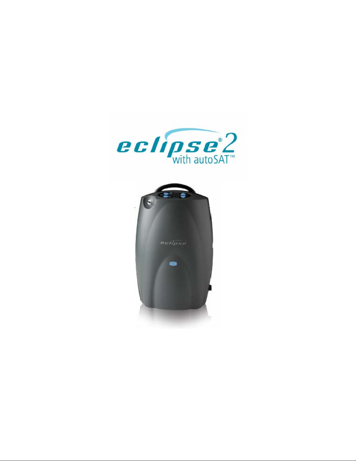
1
SeQual®Technologies Inc.
Eclipse®2 Oxygen System
Model 1000A
Provider Technical Manual

2
Table of Contents
General Information.............................................................................................................................................6
WARNING AND CAUTION STATEMENTS.................................................................................................................6
INTRODUCTION TO THE ECLIPSE 2OXYGEN SYSTEM ............................................................................................7
Eclipse Oxygen System Specifications...............................................................................................................8
OXYGEN CONCENTRATOR...................................................................................................................................8
PULSE MODE SPECIFICATIONS............................................................................................................................9
POWER ACCESSORY SPECIFICATIONS.................................................................................................................9
AC Power Supply .........................................................................................................................................9
DC Power Supply.......................................................................................................................................10
Power Cartridge (Battery)...........................................................................................................................10
INDEPENDENT SAFETY TESTING........................................................................................................................10
How The Eclipse 2 Works .................................................................................................................................13
INTRODUCTION.................................................................................................................................................14
ATF® CONCENTRATOR MODULE ......................................................................................................................14
COMPRESSOR AND COMPRESSOR ENCLOSURE .................................................................................................15
POWER DISTRIBUTION ......................................................................................................................................15
CONTROL MODULE...........................................................................................................................................15
CONTROL PANEL..............................................................................................................................................16
CONTINUOUS FLOW MODE................................................................................................................................18
PULSE FLOW MODE..........................................................................................................................................18
PROVIDER MODE FUNCTIONS............................................................................................................................19
Alarm Code.................................................................................................................................................19
Display Total Hours of Operation...............................................................................................................19
Display Software Version ...........................................................................................................................19
Pulse Mode Sensitivity Adjustment............................................................................................................19
LCD Contrast..............................................................................................................................................19
SERVICE MODE FUNCTIONS..............................................................................................................................20
Data Logging..............................................................................................................................................20
Event History..............................................................................................................................................20
Usage Meters.............................................................................................................................................20
POWER SUPPLIES.............................................................................................................................................21
AC Power Supply .......................................................................................................................................21
DC Power Supply.......................................................................................................................................22
POWER CARTRIDGE..........................................................................................................................................23
Typical New Power Cartridge Operation Time...........................................................................................24
Training A New Patient......................................................................................................................................27
INTRODUCTION.................................................................................................................................................28
Pre-Delivery Check List..............................................................................................................................28
CONTRAINDICATIONS........................................................................................................................................29
BASIC CONCEPT TRAINING................................................................................................................................30
Safety Guidelines and Operational Safety Warnings/Cautions..................................................................30
Locating the Eclipse ...................................................................................................................................30
The Users Manual......................................................................................................................................31
Showing Panel Buttons, Indicators, Alerts and Alarms..............................................................................31
Showing Power Cartridge Power Level......................................................................................................31
Selecting the Proper Flow Mode and Setting.............................................................................................31
Selecting Continuous Flow Mode...............................................................................................................32
Selecting Pulse Flow Mode........................................................................................................................32
Adjusting the Pulse Mode Sensitivity Setting.............................................................................................33
Connecting the AC Power Supply..............................................................................................................33
Connecting the DC Power Supply..............................................................................................................34

3
ACTIVE LIFESTYLE TRAINING.............................................................................................................................36
Attach the Cart............................................................................................................................................36
Using Around the House ............................................................................................................................36
Traveling by Vehicle...................................................................................................................................36
Traveling by Air...........................................................................................................................................38
Traveling by Boat........................................................................................................................................39
Traveling by Train.......................................................................................................................................39
HOW TO MAINTAIN THE ECLIPSE........................................................................................................................40
Clean the Air Inlet Filter..............................................................................................................................40
Clean and Care for the Tubing and Cannula..............................................................................................40
Clean the Cabinet and Control Panel and Power Supplies........................................................................40
Care for the Power Cartridge .....................................................................................................................41
PATIENT TRAINING CHECKLIST..........................................................................................................................42
Provider Maintenance........................................................................................................................................43
INTRODUCTION.................................................................................................................................................44
Periodic Maintenance List ..........................................................................................................................44
Checking and Replacing the Power Cartridge ...........................................................................................44
Proper Care for the Power Cartridge..........................................................................................................44
MAINTENANCE PROCEDURES............................................................................................................................45
Remove and Replace the Unit Cover.........................................................................................................45
Remove and Replace 9 Volt Battery..........................................................................................................49
Remove and Replace HEPA Filter.............................................................................................................51
Remove and Replace the Compressor Intake Filter..................................................................................54
TEST PROCEDURES..........................................................................................................................................56
Eclipse Purity and Flow Rate Test Procedure - Preferred Method............................................................56
Purity and Flow Rate Test Procedure-Alternate Method............................................................................56
Assembly and Alarm Verification Tests......................................................................................................57
Electrical Safety Test..................................................................................................................................59
Cleaning the Eclipse...................................................................................................................................59
SERVICE AND MAINTENANCE RECORD...............................................................................................................60
Shipping and Transporting the Eclipse.......................................................................................................61
Storing the Eclipse......................................................................................................................................61
Discarding...................................................................................................................................................61
System Troubleshooting and Alarms ................................................................................................................62
TROUBLESHOOTING..........................................................................................................................................62
ALARM CONDITIONS AND ALARM CODES............................................................................................................63
Service and Repair Procedures ........................................................................................................................65
SYSTEM SCHEMATICS AND DIAGRAMS...............................................................................................................66
Simplified Block diagram............................................................................................................................66
OXYGEN CIRCUIT .............................................................................................................................................68
Remove and Replace the ATF Module......................................................................................................68
Remove and Replace the Product Tank Assembly....................................................................................72
Routing Diagram for Pneumatic Tubing.....................................................................................................74
ELECTRONICS ..................................................................................................................................................75
Remove and Replace the Control Module Assembly.................................................................................75
Remove and Replace the Buzzer Wire Harness........................................................................................77
Control Module Connector Diagram...........................................................................................................78
Remove and Replace the Power Manager Printed Circuit Board..............................................................79
Power Manager PC Board Connector Diagram.........................................................................................82
COMPRESSOR..................................................................................................................................................83
Remove and Replace the Compressor Box...............................................................................................83
PREVENTATIVE MAINTENANCE PARTS ...............................................................................................................87
REPLACEMENT PARTS LIST...............................................................................................................................87
SeQual Customer Service Contact Information ................................................................................................88

4
Table of Tables
TABLE 1: PULSE PROFILES...........................................................................................................................18
TABLE 2: FLOW MODES FOR DC POWER SUPPLY OPERATION. ............................................................38
TABLE 3: ECLIPSE STARTUP SEQUENCE INDICATIONS...........................................................................57
TABLE 4: SAMPLE ECLIPSE MAINTENANCE RECORD ..............................................................................60
Table of Illustrations
FIGURE 1: ECLIPSE SYSTEM BLOCK DIAGRAM.........................................................................................12
FIGURE 2: FLOW SENSOR BOARD DIAGRAM.............................................................................................15
FIGURE 3: CONTROL PANEL BUTTONS AND INDICATORS ......................................................................14
FIGURE 4: ECLIPSE SERVICE PORT............................................................................................................20
FIGURE 5: AC POWER SUPPLY....................................................................................................................21
FIGURE 6: DC POWER SUPPLY....................................................................................................................22
FIGURE 7: ECLIPSE POWER CARTRIDGE...................................................................................................23
FIGURE 8: POWER CARTRIDGE STATUS GAUGE......................................................................................25
FIGURE 9: DC POWER SUPPLY INPUT POWER SWITCH..........................................................................37
FIGURE 10: CLEANING THE AIR INLET FILTER...........................................................................................40
FIGURE 11: MAINTENANCE TOOLS..............................................................................................................45
FIGURE 12: REMOVING SCREWS TO OPEN THE FRONT COVER............................................................46
FIGURE 13: OPENING THE FRONT COVER.................................................................................................46
FIGURE 14: REMOVING THE CONTROL PANEL RIBBON CABLE..............................................................47
FIGURE 15: DISCONNECTING THE OXYGEN OUTLET TUBE....................................................................48
FIGURE 16: FRONT COVER REMOVAL........................................................................................................48
FIGURE 17: CONTROL PANEL RIBBON CABLE INSTALLATION................................................................49
FIGURE 18: REMOVING THE 9-VOLT BATTERY..........................................................................................50
FIGURE 19: DISCONNECTING THE 9-VOLT BATTERY...............................................................................50
FIGURE 20: REMOVING THE HEPA FILTER.................................................................................................51
FIGURE 21: DISCONNECTING THE HEPA FILTER. .....................................................................................52
FIGURE 22: INSTALLING THE HEPA FILTER................................................................................................52
FIGURE 23: REMOVING THE COMPRESSOR INTAKE FILTER...................................................................54
FIGURE 24: INSTALLING THE COMPRESSOR INTAKE FILTER.................................................................55
FIGURE 25: SEQUAL RECOMMENDED TEST SETUP TO VERIFY PERFORMANCE OF OXYGEN
CONCENTRATOR.......................................................................................................................56
FIGURE 26: DATA OUTPUT FORM................................................................................................................58
FIGURE 27: ECLIPSE OXYGEN SYSTEM SIMPLIFIED BLOCK DIAGRAM.................................................66
FIGURE 28: TOP CASE COMPONENTS........................................................................................................66
FIGURE 29: BOTTOM CASE COMPONENTS................................................................................................67
FIGURE 30: REMOVAL OF ATF MODULE PRODUCT HOSE.......................................................................68
FIGURE 31: REMOVAL OF ATF MODULE PRESSURE AND VACUUM TUBES..........................................68
FIGURE 32: REMOVE ATF MODULE FROM ECLIPSE CASE. .....................................................................69
FIGURE 33: ATF MODULE GROMMET INSTALLATION...............................................................................69
FIGURE 34: TUBE ROUTING UNDER ATF MODULE....................................................................................70
FIGURE 35: PRODUCT TANK INLET AND OUTLET CONNECTIONS..........................................................72
FIGURE 36: PRODUCT TANK REMOVAL......................................................................................................73
FIGURE 37: OXYGEN TUBING ROUTING .....................................................................................................74
FIGURE 38: CONTROL MODULE REMOVAL (ATF MODULE NOT SHOWN FOR CLARITY).....................75
FIGURE 39: CONTROL MODULE INSTALLATION. .......................................................................................76
FIGURE 40: BONDING THE BUZZER TO THE CASE. ..................................................................................77
FIGURE 41: BUZZER INSTALLATION............................................................................................................77
FIGURE 42: CONTROL MODULE CONNECTOR DIAGRAM.........................................................................78

5
FIGURE 43: BATTERY BRIDGE BOARD REMOVAL.....................................................................................79
FIGURE 44: POWER MANAGER PC BOARD REMOVAL..............................................................................80
FIGURE 45: EXHAUST TUBE REMOVAL.......................................................................................................80
FIGURE 46: ATF MOTOR, 9-VOLT BATTERY, AND CONTROL PC BOARD
COMMUNICATIONS WIRE HARNESS REMOVAL....................................................................81
FIGURE 47: POWER MANAGER PC BOARD CONNECTOR DIAGRAM......................................................82
FIGURE 48: CASE BOTTOM COVER REMOVAL..........................................................................................83
FIGURE 49: COMPRESSOR BOX ELECTRICAL CONNECTIONS. ..............................................................84
FIGURE 50: EXHAUST TUBE REMOVAL.......................................................................................................84
FIGURE 51: REMOVAL OF COMPRESSOR PRESSURE AND VACUUM HOSES FROM ATF MODULE. .85
FIGURE 52: REMOVE COMPRESSOR BOX SCREWS.................................................................................86
6
General Information
This technical manual will familiarize you with Provider-specific information regarding the Eclipse 2 Oxygen
System. Instructions in this manual are intended to help ensure that:
- Providers are familiar with Eclipse system components and system principles of operation
- Patients are given proper guidance in the use of the Eclipse and its accessories
- Providers are guided in the care, maintenance, and repair of the Eclipse Oxygen System
Warning and Caution Statements
Definitions of Warnings and Cautions as used on Eclipse
WARNING:
Important safety information for hazards that might cause serious
injury.
CAUTION:
Important information for preventing damage to the Eclipse Oxygen
System.
NOTE: Places emphasis on an operating characteristic or important
consideration.
7
Introduction to the Eclipse 2 Oxygen System

8
Eclipse Oxygen System Specifications
Oxygen Concentrator
Dimensions (H x W X D) 19.3 x 12.3 x 7.1 inches
(49.0cm x 31.2cm x 18.0cm)
Weight
With Power Cartridge
Without Power Cartridge
17.9 pounds (8.1 kg)
14.5 pounds (6.6 kg)
Flow Settings
Continuous Flow
Pulse Flow
0.5 to 3.0 LPM, 0.5 LPM increments
Settings of 1.0 to 6.0, in 0.5 increments
Continuous Flow Accuracy +/- 10% or 200ml/min, whichever is greater
Oxygen concentration 90% +/- 3% for all flow settings
Maximum System Pressure 15 psig (103.5 kPa)
Oxygen Output Pressure 5.0 psig (34.5 kPa) nominal
Oxygen Concentration
Indicator Green Light = Normal Operation
Yellow Light = Warning or Caution, less than 85% ±3%
Red Light Flashing = Abnormal Operation, less than 70% ±5%
Nominal Sound Level
3 LPM Continuous Flow
0.5LPM Continuous Flow
48 dB(A)
40 dB(A)
Operating Environment
Temperature
Humidity
50º F to 104º F (+10° to 40°C)
10% to 95%, Non-condensing, 82.4°F (28°C) Maximum Dew
point
Storage Environment
Temperature
Humidity
-4º F to 140º F (-20° to 60°C)
Up to 95% Non-condensing
Nominal Power
0.5 LPM Continuous flow
3 LPM Continuous Flow
1.0 Pulse Flow Setting
6.0 Pulse Flow Setting
48 Watts
145 Watts
45 Watts
95 Watts
Nominal Power Cartridge
operating time
Continuous Flow
1.0 LPM
3.0 LPM
Pulse Flow
1.0
6.0
4.4 hours
1.3 hours
4.4 hours
2.1 hours
Continuous Flow Indication Expressed in liters per minute (LPM)
Note: Times will decrease with
higher bolus size, breath rate,
ambient temperature, power
cartridge age and use over time.

9
Audible Alarm Indicators Loss of Power/Hot Power Cartridge
Low Power Cartridge/Warm Power Cartridge
Low Oxygen Output
O2Flow Outside Normal Limits
Unit Malfunction
Back-Up Alarm Power 9V Internal Battery
Filters Air Inlet, HEPA, Compressor Intake
Device Classification IEC Class I, Type B Applied Part, IPX0
Pulse Mode Specifications
Pulse Settings 1.0 to 6.0, in increments of 0.5
Trigger Sensitivity Adjustable between settings of 1 (most sensitive) to 6 (least sensitive)
Trigger Criteria •Cannula pressure has dropped below the trigger point (typically
between 0.15 – 0.45 Cm of H2O of negative pressure)
•At least 1¼ seconds has passed since the last pulse began
Minimum time between
breaths 1.25 seconds (max. 3 consecutive breaths)
Response to Missing
Breaths •Yellow LED is activated if no inspiration has been detected after 45
seconds.
•Switch to Continuous Mode if no inspiration has been detected for
60 seconds with an audible alarm.
Bolus Volume and Breath Rates
AC Power
Supply and
Power Cartridge
10 Amp
Switch Setting
DC Power Supply
15 Amp
Switch Setting
DC Power Supply
Pulse
Flow
Setting
Bolus Size
(± 15%)
Min
Breath
Rate Max Breath
Rate Max Breath
Rate Max Breath
Rate
1.0 16 6 40 40 40
2.0 32 6 40 40 40
3.0 48 6 40 40 40
4.0 64 6 39 31 39
5.0 80 6 31 25 31
6.0 96 6 26 20 26
Power Accessory Specifications
AC Power Supply
Input Voltage 100-240VAC, 50-60 Hz
Input Power 245-260 VA
Output Voltage 28 VDC
Output Power 200W

10
DC Power Supply
Input Voltage 11.5-18VDC
Output Voltage 26 VDC
Output Power 150W Max
Power Cartridge (Battery)
Output voltage 14.8 VDC
Capacity Quantity (2) 97.5 W-hrs batteries
(Each containing 7.92 grams
equivalent Lithium content)
Nominal Power Cartridge
Life 80% Capacity after 500
Charge/Discharge cycles
Power Cartridge Recharge
Time 1.4 to 5.0 hours, dependent on flow
setting, to achieve 80% capacity from a
fully discharged Power Cartridge
Independent Safety Testing
Eclipse System and Eclipse Concentrator, Model 1000A
Safety IEC 60601-1 :1988 + A1 :1991 + A2 :1995 + Corrigendum (6/95)
EN 60601-1(1990) + A1(1993) + A2(1995) + A12(1993) + A13(1996) + Corrigenda (7/94)
Electromagnetic
Compatibility FCC 15B (Sec. 107 & 109), EN55011, EN60601-1-2 :2001, EN6100-3-2, EN61000-3-3,
IEC61000-4-2, IEC61000-4-3, IEC61000-4-4, IEC61000-4-5, IEC61000-4-6, IEC61000-4-8,
IEC61000-4-11, IEC 60601-1-2 :2001, RTCA DO 160 Rev E
AC Power Supply, Model 4123
Safety IEC 60601-1:1988 + A1:1991 + A2:1995
Electromagnetic
Compatibility FCC 15B (Sec. 107 & 109), EN55011, EN60601-1-2 :2001, EN6100-3-2, EN61000-3-3,
IEC61000-4-2, IEC61000-4-3, IEC61000-4-4, IEC61000-4-5, IEC61000-4-6, IEC61000-4-8,
IEC61000-4-11, EN55014-1
DC Power Supply, Model 4124
Safety Portions of IEC 60601-1:1988 + A1:1991 + A2:1995
Electromagnetic
Compatibility FCC 15B (Sec. 109), EN55011, EN60601-1-2 :2001, IEC61000-4-2, IEC61000-4-3,
IEC61000-4-4, IEC61000-4-6, IEC 60601-1-2 :2001
Power Cartridge 2400, PN 1056
Safety UL2054, UL60950-1, First Edition (UL File MH29443), IEC 60601-1:1988 + A1:1991 +
A2:1995, UN Transportation Tests T1-T8
Electromagnetic
Compatibility EN 61000-6-3 :2001 (EN55022 :1998+A1 :2001+A2 :2003), EN61000-6-1 :2001, EN61000-4-
2 :1995+A1 :1998, EN61000-4-3 :2002
Any CSA-CUS mark for the Eclipse system does not encompass operation with the DC Power Supply Model
4124.

11
ELECTROMAGNETIC COMPATIBILITY
This equipment has been tested and found to comply with the limits for medical devices to the
IEC60601-1-2 Electromagnetic Compatibility standard. These limits are designed to provide
reasonable protection against harmful interference in a typical medical installation. This equipment
generates, uses, and can radiate radio frequency energy and, if not installed according with the
instructions, may cause harmful interference to other devices in the vicinity. However, there is no
guarantee that interference will not occur in a particular installation. If this equipment does cause
harmful interference to other devices, which can be determined by turning the equipment off and on,
the user is encouraged to try to correct the interference by one or more of the following measures:
•Reorient or relocate the receiving device.
•Increase the separation distance between the equipment.
•Connect the equipment into an outlet on a circuit different from that which the other device(s)
are connected.
•Consult with SeQual Technical Support for help.
Guidance and Manufacturer's declaration - electromagnetic
emissions
The SeQual Technologies Eclipse Oxygen System is intended for use in the electromagnetic
environment specified below. The customer or the user of the SeQual Technologies Eclipse
Oxygen System should assure that it is used in such an environment.
Emissions Test Compliance Electromagnetic environment - guidance
RF emissions
EN 55011 Group 1 The SeQual Technologies Eclipse Oxygen System
uses RF energy only for its internal function.
Therefore, its RF emissions are very low and are
not likely to cause any interference in nearby
electronic equipment.
RF emissions
EN 55011 Class B
Harmonic emissions
IEC 61000-3-2 Class A
Voltage fluctuations/
flicker emissions
IEC 61000-3-3
Complies
The SeQual Technologies Eclipse Oxygen System
is suitable for use in all establishments, including
domestic establishments and those directly
connected to the public low - voltage power supply
network that supplies buildings used for domestic
purposes.

12
-PAGE INTENTIONALLY BLANK-

13
How The Eclipse 2 Works
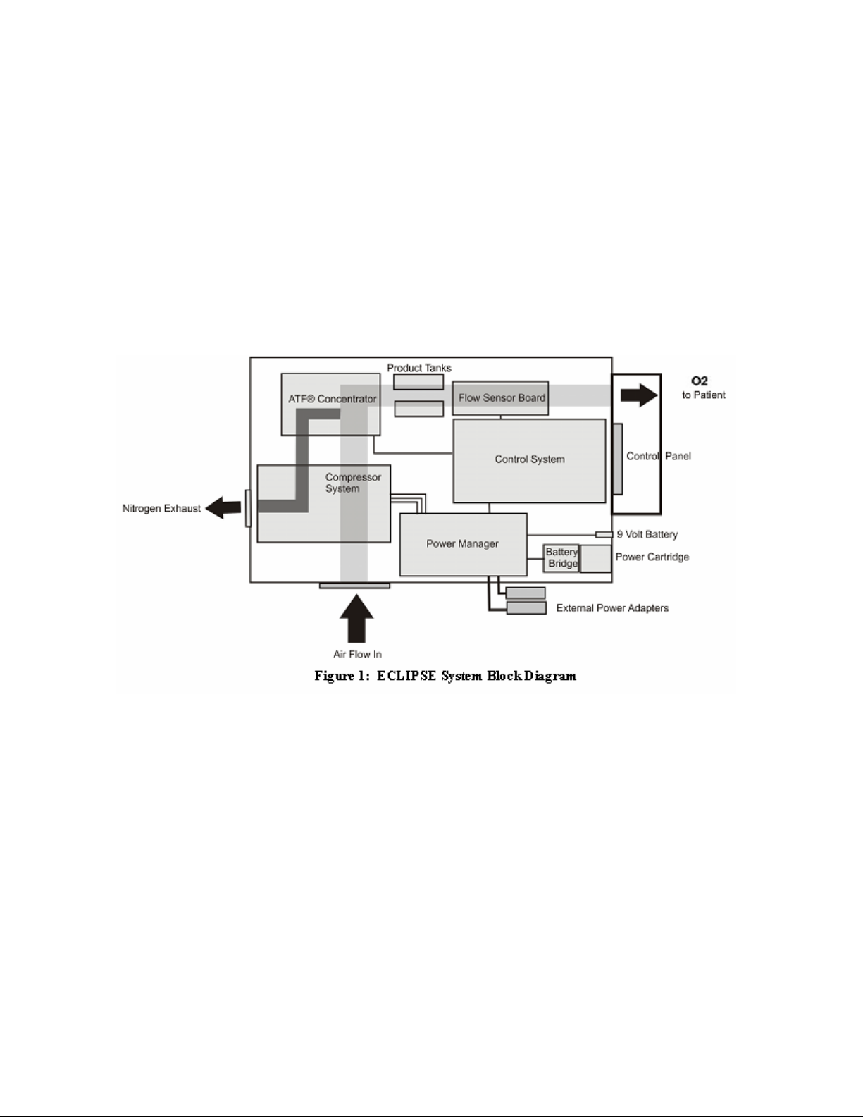
14
Introduction
The Eclipse 2, Personal Ambulatory Oxygen System with AutoSat Technology is a portable medical
device used to extract oxygen from the atmosphere, concentrate it to greater than 90% and present it to
the patient. The device will operate in continuous flow or Pulse Flow Modes. In Continuous Flow Mode
the oxygen is provided at a constant flow rate between 0.5 and 3.0 LPM. In Pulse Flow Mode, oxygen is
supplied in a bolus at the beginning of each inspiration, providing a selectable range setting of flow
between 1.0 and 6.0. A setting of 1 in Pulse Flow Mode delivers the equivalent amount of oxygen
(FIO2) as a Continuous Flow Mode setting of 3 LPM.
The Eclipse operates from either external power or from an internal rechargeable Power Cartridge. The
system includes a “Smart Battery” charger that recharges the internal Power Cartridge whenever the
Eclipse is connected to external power. The system monitors and controls both the power source and
the Power Cartridge charger.
ATF® Concentrator Module
The Eclipse uses a passive system to separate oxygen from air. Air flows into the Eclipse where it is
filtered and then enters the compressor. Pressurized air flows from the compressor into the ATF®
Concentrator Module where it is separated into oxygen and nitrogen components. The air separation
process uses a rotary valve system to force air through a series of pressurized sieve beds. Through a
process known as “pressure swing adsorption,” nitrogen molecules are collected on an adsorbent
material allowing the concentrated oxygen to be forced through a sieve bed into the product tank. The
nitrogen molecules are then purged from the adsorbent material using a vacuum pressure cycle.
Oxygen flows from the product tank through a HEPA filter and past a sensor that measures flow and
concentration. A flow control valve regulates the flow of concentrated oxygen presented to the patient.
The process is continuously repeated during operation.

15
Compressor and Compressor Enclosure
The Eclipse compressor is a two-cylinder, variable speed wobble piston compressor, driven by a highly
efficient Brushless DC (BLDC) motor. When air flows into the compressor enclosure, it passes through
an air intake filter/muffler that muffles sound and filters out impurities. Using one cylinder, the
compressor takes in filtered air and delivers it to the ATF Module under pressure. The second cylinder
draws a vacuum on the ATF module and exhausts nitrogen rich gas to the exhaust vent.
Using a multifaceted approach, sound, heat, and vibration generated by the compressor are mitigated by
the compressor enclosure. Vibration and structure-borne noise are addressed by the dual axis gimbal
that supports the compressor and the tubing that connects the compressor to the ATF module. The rigid
walls of the compressor enclosure and the sound adsorbing foam that lines it diminish the radiated noise.
The centrifugal blower mounted within the compressor enclosure serves to efficiently draw cooling air in
over the compressor cylinders while simultaneously pushing exhaust gas out of the concentrator.
Power Distribution
The Power Manager takes external power that comes into the Eclipse from the power supplies or Power
Cartridge and monitors and controls power distribution to the rest of the Eclipse system. The Power
Manager drives the compressor, ATF module motor, blower, and provides power to the control module.
In addition, when the unit is connected to an external power source, the power manager monitors and
controls the recharging of the Power Cartridge.
Control Module
The control module is at the center of nearly all Eclipse functions. The module constantly monitors
dynamics such as temperatures, pressures, product flow and concentration, and user input. It
determines proper compressor and ATF motor speeds needed in order to provide optimum system
performance. In addition, this system supports the operation of the Control Panel and its indicators.
The Control Module utilizes a proprietary ultrasonic flow and concentration sensor and a flow control
valve to accurately control the flow of oxygen in Continuous and Pulse Flow Modes.
Figure 2: Flow Sensor Diagram

16
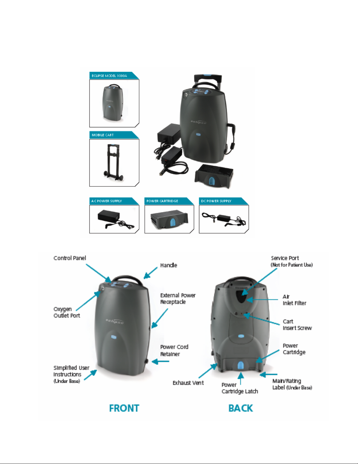
Control Panel
The control panel provides a user interface consisting of a membrane panel keyboard, Liquid Crystal
Display (LCD), external power present indicator, Power Cartridge capacity indicator, alarm status
indicators, and an audio transducer. The user interface informs the user of the system status and allows
the user to set the desired flow rate and flow mode.
Figure 3

17

18
Continuous Flow Mode
The user may set the Eclipse oxygen flow rate and mode. Continuous Flow Mode delivers a constant
flow of oxygen to a patient by means of tubing and a nasal cannula at rates between 0.5 LPM and 3.0
LPM. Within the Eclipse, concentrated oxygen is stored in a 500ml product tank at pressures in the
range of 5 to 9 psi. This pressure gives Continuous Flow Mode the capability to deliver the indicated flow
rate to the patient even if extension tubing is used, up to 50 feet long. In addition, the Eclipse
Continuous Flow Mode is fully compatible with humidifier use.
Pulse Flow Mode
The Eclipse Pulse Flow Mode delivers a high flow of oxygen at the very beginning of each inspiration.
The approach is based on the manner in which gas is absorbed into a patient’s airway. Eclipse users
may select pulse volume delivery rates at settings between 1 and 6. Regardless of setting, the pulse
profile is a simple square-wave pulse based on a 16-ml/liter volume. (Refer to “Pulse Profiles” table
below). Pulse durations are no less than 100 milli-seconds. Pulse durations do not exceed 450 milli-
seconds due to dead space considerations.
Flow
Setting
Pulse Peak
Flow, LPM
(volumetric)
Pulse Duration
(milli-second)
Bolus
Volume
(ml)
1 8 120 16
2 9 213 32
3 10 288 48
4 11 349 64
5 12 400 80
6 13 443 96
Table 1: Pulse Profiles
The fundamental approach to triggering and controlling the oxygen bolus in Pulse Flow mode is as
follows:
The user may select a pulse trigger sensitivity in settings ranging from 1 to 6. The pulse will be triggered
when the system meets all of the following criteria:
•The cannula pressure has dropped below the trigger point (typically between 0.15 and 0.45
cmH20)
•At least 1¼ seconds has passed since the last pulse began

19
Provider Mode Functions
Providers can access provider mode software functions using the control panel. All provider mode
information is displayed on the LCD. The software shall advance the following display mode when the
“No Smoking” icon is pressed:
1. Alarm Code (AC)
2. Hours of Operation (H)
3. 9-volt Battery Status (9V)
4. Software Version (SW)
5. Pulse Sensitivity (PS)
6. LCD Contrast (CT)
Alarm Code
While in Continuous Flow Mode, pressing the “No Smoking” icon displays the current Eclipse alarm code
on the LCD. This code may be used to help diagnose conditions indicated by the alert and alarm
indicators. The LCD will show “AC=”. Refer to the “Provider Maintenance” section for further
information.
Hours of Operation
The Eclipse hour meter provides valuable information on hours of operation. Providers may display the
total number of hours of operation using the control panel. The display counts up to “99,999.9” hours,
then rolls over to “00000.” The LCD will show “H=”. Refer to the “Provider Maintenance” section for
further information.
9-Volt Battery Status
The status of the 9-Volt Battery is provided. This is the actual voltage of the 9-Volt battery. The LCD will
show “9V=”.
Software Version
Providers may occasionally need to obtain the software version on the Eclipse to perform maintenance.
The provider may display software version numbers for both the Control System and the Power Manager
software using the control panel. Refer to the “Provider Maintenance” section for further information.
Pulse Mode Sensitivity Adjustment
During patient setup, a qualified clinician may adjust the Pulse Mode sensitivity to best suit patient
inspiratory effort. The LCD will show “PS=”.
LCD Contrast
Providers may need to adjust the LCD contrast. The contrast may be set from O to 10, with 10 being
the highest contrast. The LCD will show “CT=”.
20
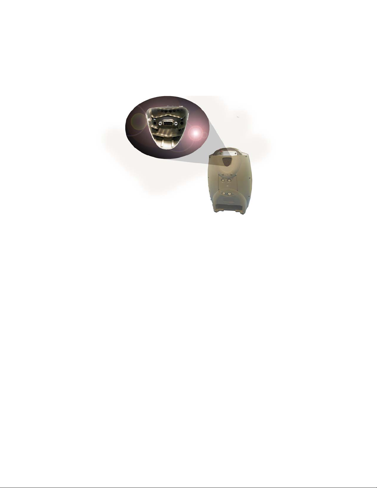
Service Mode Functions
Factory maintenance or service updates may sometimes be required on the Eclipse. Factory and
qualified factory-trained technicians can access service mode software functions by using the Service
Port located on the back of the unit. The Service Port is not for patient use.
Figure 4: Eclipse Service Port
Data Logging
The Eclipse provides various operational data on demand. Data that may be reported includes:
•System Status
•Compressor Speed
•Component Temperature
•Power Cartridge Data
•Oxygen flow rate and purity
•Process pressure and temperature
•Breath detection (Pulse Mode Only)
•Bolus Delivery (Pulse Mode Only)
•External Power
Event History
The Eclipse detects and records events such as changes in status, alarm states, and changes in user
settings.
Usage Meters
The Eclipse usage meter provides the following information:
•Total hours of operation.
•Total hours of operation at High and Low compressor temperatures
•Total hours of operation at Low, Medium, and High compressor speeds
This manual suits for next models
1
Table of contents
Other SeQual Technologies Medical Equipment manuals

Popular Medical Equipment manuals by other brands


Bauerfeind
Bauerfeind SecuTec Omo instructions

Otto Bock
Otto Bock E-MAG Active Instructions for use

dideco
dideco D 905 EOS Instructions for use

ResMed
ResMed ClimateLineAir 11 user guide

Molnlycke
Molnlycke Mepilex Border Flex Safetac manual

Shenzhen Roundwhale Technology Co., LTD.
Shenzhen Roundwhale Technology Co., LTD. R-C4D instruction manual


