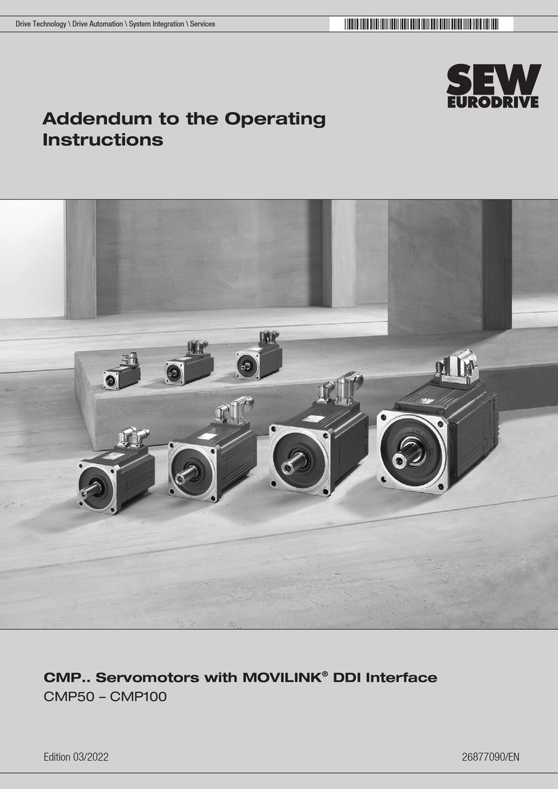
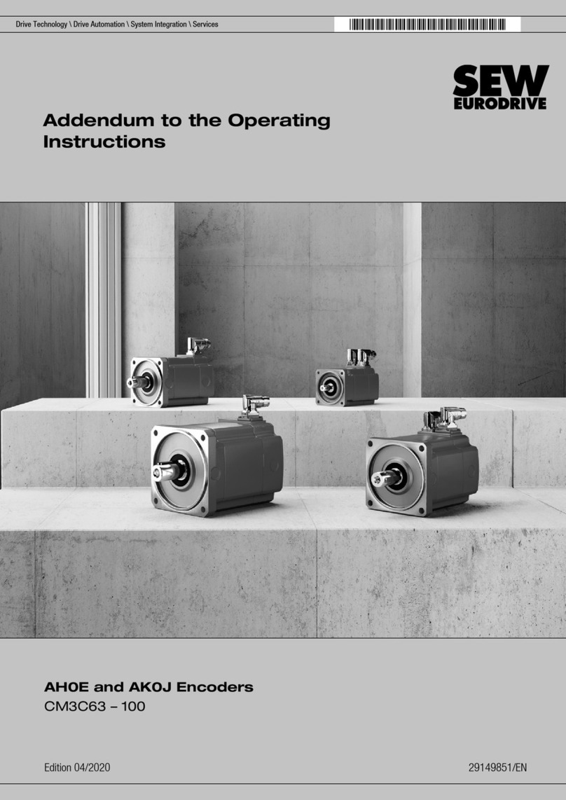
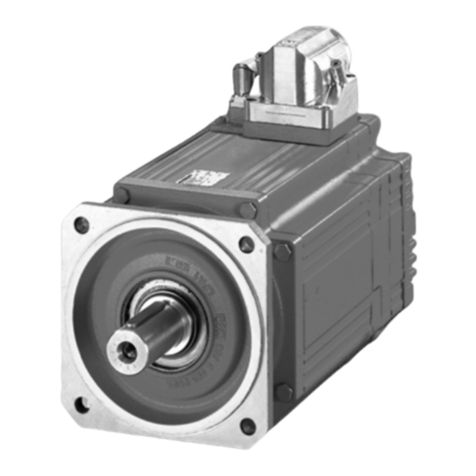
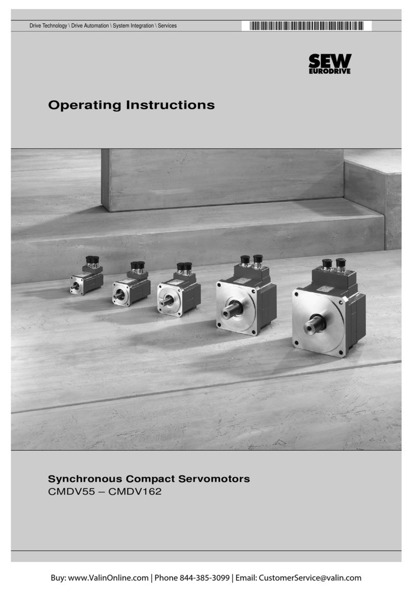
SEW-Eurodrive CMP40 User manual

*21923582_0715*
Drive Technology \ Drive Automation \ System Integration \ Services
Operating Instructions
Synchronous Servomotors
CMP40 – CMP112, CMPZ71 – CMPZ100
Edition 07/2015 21923582/EN

SEW-EURODRIVE—Driving the world

Contents
Operating Instructions – CMP40 – CMP112, CMPZ71 – CMPZ100 3
Contents
1 General information.................................................................................................................. 5
1.1 About this documentation ...............................................................................................5
1.2 Structure of the safety notes ...........................................................................................5
1.3 Rights to claim under limited warranty ............................................................................7
1.4 Exclusion of liability.........................................................................................................7
1.5 Product names and trademarks......................................................................................7
1.6 Copyright notice ..............................................................................................................7
1.7 Motor type notation .........................................................................................................7
2 Safety notes .............................................................................................................................. 8
2.1 Preliminary information ...................................................................................................8
2.2 General information ........................................................................................................8
2.3 Target group ...................................................................................................................9
2.4 Functional safety technology (FS) ................................................................................10
2.5 Designated use .............................................................................................................11
2.6 Other applicable documentation ...................................................................................11
2.7 Transport/storage..........................................................................................................12
2.8 Installation/assembly.....................................................................................................12
2.9 Electrical connection .....................................................................................................13
2.10 Safety notes on the motor.............................................................................................14
2.11 Startup ..........................................................................................................................15
3 Motor structure ....................................................................................................................... 16
3.1 Basic structure of CMP40 – CMP63 .............................................................................16
3.2 Basic structure of CMP40 – CMP63/BK .......................................................................17
3.3 Basic structure of CMP71 – CMP100/BP .....................................................................18
3.4 Basic structure of CMP112 – CMP112/BY/KK/VR........................................................19
3.5 Basic structure of CMPZ71 – CMPZ100/BY/KK/VR .....................................................20
3.6 Nameplate and unit designation ...................................................................................21
3.7 Variants and options of the CMP. motor series ............................................................24
4 Mechanical installation .......................................................................................................... 26
4.1 Before you start.............................................................................................................26
4.2 Required tools/resources ..............................................................................................26
4.3 Long-term storage of servomotors................................................................................26
4.4 Motor installation notes .................................................................................................28
4.5 Installation tolerances ...................................................................................................29
4.6 Options..........................................................................................................................30
5 Electrical installation.............................................................................................................. 33
5.1 Additional regulations....................................................................................................33
5.2 Compulsory use of the wiring diagrams........................................................................33
5.3 Wiring notes ..................................................................................................................34
5.4 Notes regarding the connection of the power and signal cables via the connector
system ..........................................................................................................................35
5.5 Notes regarding the connection of the power and signal cables via the terminal box ..38
5.6 Connecting the motor and the encoder system via plug connector SM./ SB................39
21923582/EN – 07/2015

Contents
Operating Instructions – CMP40 – CMP112, CMPZ71 – CMPZ100
4
5.7 Connecting the motor and encoder system via KK / KKS terminal box........................59
5.8 Options..........................................................................................................................72
6 Startup ..................................................................................................................................... 77
6.1 Before startup ...............................................................................................................78
6.2 During startup ...............................................................................................................79
7 Inspection/maintenance......................................................................................................... 80
7.1 General information .....................................................................................................81
7.2 Maintenance intervals ...................................................................................................82
7.3 Notes on the BP brake..................................................................................................83
7.4 Notes on the BK brake..................................................................................................83
7.5 Notes on the BY brake..................................................................................................84
8 Technical data......................................................................................................................... 92
8.1 Technical data of BK brakes .........................................................................................92
8.2 Technical data of the BP brake.....................................................................................94
8.3 Technical data of the BY brake.....................................................................................98
8.4 Safety categories of standard design..........................................................................106
9 Malfunctions.......................................................................................................................... 107
9.1 Customer service ........................................................................................................107
9.2 Encoder malfunctions .................................................................................................108
9.3 Malfunctions of the servo inverter ...............................................................................108
9.4 Disposal ......................................................................................................................108
Index ...................................................................................................................................... 109
10 Address list ........................................................................................................................... 112
21923582/EN – 07/2015

1
General information
About this documentation
Operating Instructions – CMP40 – CMP112, CMPZ71 – CMPZ100 5
1 General information
1.1 About this documentation
This documentation is an integral part of the product. The documentation is intended
for all employees who perform assembly, installation, startup, and service work on the
product.
Make sure this documentation is accessible and legible. Ensure that persons respons-
ible for the machinery and its operation as well as persons who work on the device in-
dependently have read through the documentation carefully and understood it. If you
are unclear about any of the information in this documentation or require further in-
formation, contact SEW‑EURODRIVE.
1.2 Structure of the safety notes
1.2.1 Meaning of signal words
The following table shows the grading and meaning of the signal words for safety
notes.
Signal word Meaning Consequences if disregarded
DANGER Imminent hazard Severe or fatal injuries.
WARNING Possible dangerous situation Severe or fatal injuries.
CAUTION Possible dangerous situation Minor injuries
NOTICE Possible damage to property Damage to the drive system or its
environment.
INFORMATION Useful information or tip: Simplifies
handling of the drive system.
21923582/EN – 07/2015

1General information
Structure of the safety notes
Operating Instructions – CMP40 – CMP112, CMPZ71 – CMPZ100
6
1.2.2 Structure of section-related safety notes
Section-related safety notes do not apply to a specific action but to several actions
pertaining to one subject. The hazard symbols used either indicate a general hazard
or a specific hazard.
This is the formal structure of a safety note for a specific section:
SIGNAL WORD
Type and source of hazard.
Possible consequence(s) if disregarded.
• Measure(s) to prevent the hazard.
Meaning of the hazard symbols
The hazard symbols in the safety notes have the following meaning:
Hazard symbol Meaning
General hazard
Warning of dangerous electrical voltage
Warning of hot surfaces
Warning of risk of crushing
Warning of suspended load
Warning of automatic restart
1.2.3 Structure of embedded safety notes
Embedded safety notes are directly integrated into the instructions just before the de-
scription of the dangerous action.
This is the formal structure of an embedded safety note:
• SIGNAL WORD Type and source of hazard.
Possible consequence(s) if disregarded.
– Measure(s) to prevent the hazard.
21923582/EN – 07/2015

1
General information
Rights to claim under limited warranty
Operating Instructions – CMP40 – CMP112, CMPZ71 – CMPZ100 7
1.3 Rights to claim under limited warranty
Read the information in this documentation. This is essential for fault-free operation
and fulfillment of any rights to claim under limited warranty. Read the documentation
before you start working with the unit!
1.4 Exclusion of liability
Read the information in this documentation, otherwise safe operation is impossible.
You must comply with the information contained in this documentation to achieve the
specified product characteristics and performance features. SEW‑EURODRIVE as-
sumes no liability for injury to persons or damage to equipment or property resulting
from non-observance of these operating instructions. In such cases,
SEW‑EURODRIVE assumes no liability for defects.
1.5 Product names and trademarks
The brands and product names in this documentation are trademarks or registered
trademarks of their respective titleholders.
1.6 Copyright notice
©2015SEW‑EURODRIVE. All rights reserved.
Unauthorized reproduction, modification, distribution or any other use of the whole or
any part of this documentation is strictly prohibited.
1.7 Motor type notation
These operating instructions cover the motor types CMP and CMPZ.
If information refers to both CMP and CMPZ motors, the notation CMP. motors is
used.
If information refers to either CMP or CMPZ motors, the motor type is stated explicitly.
21923582/EN – 07/2015

2Safety notes
Preliminary information
Operating Instructions – CMP40 – CMP112, CMPZ71 – CMPZ100
8
2 Safety notes
The following basic safety notes must be read carefully to prevent injury to persons
and damage to property. The user must ensure that the basic safety notes are read
and observed. Ensure that persons responsible for the machinery and its operation as
well as persons who work on the unit independently have read through the document-
ation carefully and understood it. If you are unclear about any of the information in this
documentation, or if you require further information, contact SEW‑EURODRIVE.
2.1 Preliminary information
The following safety notes mainly apply to the use of CMP motors. If using gearmo-
tors, please also refer to the safety notes for gear units in the corresponding operating
instructions.
Also observe the supplementary safety notes in the individual sections of this docu-
mentation.
2.2 General information
DANGER
During operation, the motors and gearmotors can have live, bare (in the event of
open connectors/terminal boxes) and movable or rotating parts as well as hot sur-
faces, depending on their enclosure.
Severe or fatal injuries.
• All work related to transportation, storage, installation, assembly, connection,
startup, maintenance and repair may only be carried out by qualified personnel,
in strict observance of:
– The relevant detailed operating instructions,
– The warning and safety signs on the motor/gearmotor,
– All other project planning documents, operating instructions and wiring dia-
grams related to the drive,
– The specific regulations and requirements for the system and
– The national/regional regulations governing safety and the prevention of acci-
dents.
• Never install damaged products
• Report any damage to the shipping company immediately.
Removing the required protection cover or the housing without authorization, improper
use as well as incorrect installation or operation may result in severe injuries to per-
sons or damage to property.
This documentation provides additional information.
21923582/EN – 07/2015

2
Safety notes
Target group
Operating Instructions – CMP40 – CMP112, CMPZ71 – CMPZ100 9
2.3 Target group
Any mechanical work may only be performed by adequately qualified personnel. Qual-
ified personnel in the context of this documentation are persons familiar with the
design, mechanical installation, troubleshooting and servicing of the product, who pos-
sess the following qualifications:
• Training in mechanical engineering, e.g. as a mechanic or mechatronics technician
(final examinations must have been passed).
• They are familiar with this documentation.
Any electronic work may only be performed by adequately qualified electricians. Quali-
fied electricians in the context of this documentation are persons familiar with electrical
installation, startup, troubleshooting and servicing of the product, who possess the fol-
lowing qualifications:
• Training in electrical engineering, e.g. as an electrician or mechatronics technician
(final examinations must have been passed).
• They are familiar with this documentation.
In addition to that, they must be familiar with the relevant safety regulations and laws,
especially with the requirements of the performance levels according to
DINENISO13849‑1 and all other standards, directives and laws specified in this doc-
umentation. The above-mentioned persons must have the express authorization of the
company to operate, program, parameterize, label and ground units, systems and cir-
cuits in accordance with the standards of safety technology.
All work in the areas of transportation, storage, operation and waste disposal must be
carried out by persons who are trained appropriately.
21923582/EN – 07/2015

2Safety notes
Functional safety technology (FS)
Operating Instructions – CMP40 – CMP112, CMPZ71 – CMPZ100
10
2.4 Functional safety technology (FS)
INFORMATION
For the "Synchronous Servomotors" operating instructions, addendums are available
for the documentation "Functional Safety for CMP Synchronous Servomotors" at
www.sew‑eurodrive.com.
SEW‑EURODRIVE drives can be supplied with safety-rated components on request.
SEW‑EURODRIVE indicates such an integration by the FS mark and a number on the
nameplate.
The number is a code that indicates which components in the motor are safety-re-
lated. See the following excerpt from the code table for all products:
Functional
safety
Inverters Motor monitoring
(e.g.
motor protection)
Encoder Brake Brake monitor-
ing (e.g. func-
tion)
Manual brake
release
01 x
02 x
03 x
04 x
05 x x
06 x x
07 x x
08 x x
09 x x
10 x x
11 x x
If the FS logo on the nameplate contains the code "FS 04", for example, the motor is
equipped with a safe encoder.
You can determine the safety level of machines and plants using the characteristic
safety values provided in chapter "Technical Data" of the relevant documentation.
The characteristic safety values of components by SEW‑EURODRIVE are also avail-
able on www.sew‑eurodrive.de and in the SEW‑EURODRIVE library for the Sistema
software of the Institute for Occupational Safety and Health of the German Social Ac-
cident Insurance (IFA, formerly BGIA).
21923582/EN – 07/2015

2
Safety notes
Designated use
Operating Instructions – CMP40 – CMP112, CMPZ71 – CMPZ100 11
2.5 Designated use
These motors are intended for industrial systems.
Observe the applicable standards and directives in your country for assembly, installa-
tion, and operation of the motor.
For the installation and operation of the motor as well as for startup and recurring
technical checks, national and international regulations apply, especially:
• Machinery Directive 2006/42/EC
• EMC Directive 2004/108/EC
• Low Voltage Directive 2006/95/EC
• Accident prevention regulations and safety rules
Using these products in potentially explosive atmospheres is prohibited, unless spe-
cifically designated otherwise.
Air-cooled versions are designed for ambient temperatures of -20°C to +40°C and in-
stallation altitudes ≤ 1000m above sea level. Any differing specifications on the name-
plate must be observed. The ambient conditions must comply with all the specifica-
tions on the nameplate.
2.6 Other applicable documentation
The following publications and documents have to be observed as well:
• Wiring diagrams provided with the motor
• "Gear Unit Series R..7, F..7, K..7, K..9, S..7, SPIROPLAN® W" operating instruc-
tions for gearmotors
• Operating instructions "Gear Unit Series BS.F.., PS.F.. and PS.C.."
• Catalog "Synchronous Servomotors"
• Catalog for "Synchronous Servo Gearmotors"
• If required, addendum to the operating instructions "Safety-Rated Encoders –
Functional Safety for Synchronous Servomotors CMP"
• "Cable Prefabrication" manual
• Safe brake system "Synchronous Servomotors"
• Addendum to the operating instructions "Safety-Rated Brakes – Functional Safety
for CMP71 – CMP100, CMPZ71 – CMPZ100Z"
21923582/EN – 07/2015

2Safety notes
Transport/storage
Operating Instructions – CMP40 – CMP112, CMPZ71 – CMPZ100
12
2.7 Transport/storage
Inspect the shipment for damage as soon as you receive the delivery. Inform the ship-
ping company immediately about any damage. It may be necessary to suspend star-
tup.
Tighten the eyebolts securely. They are only designed for the weight of the motor/
gearmotor; do not attach any additional loads.
The installed eyebolts are in accordance with DIN580. The loads and regulations spe-
cified in that document must always be observed. If the gearmotor is equipped with
two eyebolts, then both of these should be used for transportation. In this case, the
tension force vector of the slings must not exceed a 45° angle in accordance with
DIN580.
Use suitable, sufficiently rated handling equipment if necessary. Reattach these in the
case of further transportation.
Store the motor in a dry, dust-free environment if it is not to be installed straight away.
The motor can be stored for one year without requiring any special measures before
startup.
2.8 Installation/assembly
Ensure that the unit is installed and cooled according to the regulations in this docu-
mentation.
Protect the unit from excessive strain. Ensure that components are not deformed and
that insulation spaces are maintained, particularly during transportation. Electric com-
ponents must not be mechanically damaged or destroyed.
The following applications are prohibited unless explicitly permitted:
• Use in potentially explosive atmospheres.
• Use in areas exposed to harmful oils, acids, gases, vapors, dust, radiation, etc.
• Use in applications that are subject to mechanical vibration and shock loads in ex-
cess of the requirements in EN 61800-5-1.
Observe the notes in the chapter "Mechanical installation".
21923582/EN – 07/2015

2
Safety notes
Electrical connection
Operating Instructions – CMP40 – CMP112, CMPZ71 – CMPZ100 13
2.9 Electrical connection
WARNING
Risk of injury due to electric shock.
Severe or fatal injuries.
• Wire the motor according to the regulations.
All work may only be carried out by qualified personnel. During work, the low-voltage
machine must be at standstill, de-energized, and safeguarded against accidental re-
start. This also applies to auxiliary circuits (e.g. anti-condensation heating or forced
cooling fan).
Perform electrical installation according to the pertinent regulations (e.g. cable cross
sections, fusing, protective conductor connection). For any additional information, refer
to the applicable documentation.
Comply with the regulations of the following standards and directives:
• EN 60034-1, rotating electrical machines
• EN 50110, operation of electrical installations
• IEC60664, insulation coordination for equipment within low-voltage systems
• EN60204-1, safety of machinery - electrical equipment of machines
• EN61800-5-1, adjustable speed electrical power drive systems
The connection must be a permanently secure electrical connection (no protruding
wire ends); use the cable end equipment intended for this purpose. Establish a safe
PE connection. When the motor is connected, the distances to non-insulated and live
parts must not be shorter than the minimum values according to IEC60664 and na-
tional regulations. With low voltage, the distances should be no shorter than the fol-
lowing values, in compliance with IEC60664:
Nominal voltage VNDistance
≤ 500V 3mm
≤ 690V 5.5mm
Observe the notes in the "Electrical installation" chapter.
21923582/EN – 07/2015

2Safety notes
Safety notes on the motor
Operating Instructions – CMP40 – CMP112, CMPZ71 – CMPZ100
14
2.10 Safety notes on the motor
CAUTION
Safety notes or signs can become dirty or illegible over time.
Risk of injury due to illegible symbols.
• Always make sure that safety, warning, and operating notes are legible.
• Replace damaged safety notes and signs.
The safety notes on the motor must be observed. They have the following meaning:
Safety note Meaning
Do not unplug the signal plug connector while it is ener-
gized!
–
17123852
–
–
For motors with BK brake:
It is essential that you observe the correct polarity of the
BK brake supply. Check the polarity when replacing the
brake.
21923582/EN – 07/2015

2
Safety notes
Startup
Operating Instructions – CMP40 – CMP112, CMPZ71 – CMPZ100 15
2.11 Startup
WARNING
Risk of injury due to missing or defective protection covers.
Severe or fatal injuries.
• Install the protective covers of the system according to the instructions.
• Never start up the motor if the protective covers are not installed.
2.11.1 Regenerative operation
Moving the output element generates a voltage at the pin contacts of the plug con-
nectors.
CAUTION
Electric shock due to regenerative operation.
Minor injuries.
• Do not touch the pin contacts in the plug connector.
• If the mating connector is not plugged in, attach a touch guard to the plug con-
nector.
21923582/EN – 07/2015

3Motor structure
Basic structure of CMP40 – CMP63
Operating Instructions – CMP40 – CMP112, CMPZ71 – CMPZ100
16
3 Motor structure
INFORMATION
The following illustrations are intended to explain the general structure. Differences
are possible depending on the motor size and design.
3.1 Basic structure of CMP40 – CMP63
[105]
[11]
[1]
[44]
[313]
[314]
[304]
[305]
[42]
[16]
[7]
[106]
18014401400042251
[1] Rotor [105] Shim
[7] Flange [106] Oil seal
[11] Deep groove ball bearing [304] Housing cover
[16] Stator [305] Resolver
[42] Endshield [313] SM/SB signal plug connector
[44] Deep groove ball bearing [314] SM/SB power plug connector
21923582/EN – 07/2015

3
Motor structure
Basic structure of CMP40 – CMP63/BK
Operating Instructions – CMP40 – CMP112, CMPZ71 – CMPZ100 17
3.2 Basic structure of CMP40 – CMP63/BK
[105]
[11]
[1]
[44]
[106] [7]
[16]
[42]
[550]
[305]
[304]
[313]
[314]
9092601867
[1] Rotor [106] Oil seal
[7] Flange [304] Housing cover
[11] Deep groove ball bearing [305] Resolver
[16] Stator [313] SM/SB signal plug connector
[42] Brake endshield [314] SM/SB power plug connector
[44] Deep groove ball bearing [550] BK permanent magnet brake
[105] Shim
21923582/EN – 07/2015

3Motor structure
Basic structure of CMP71 – CMP100/BP
Operating Instructions – CMP40 – CMP112, CMPZ71 – CMPZ100
18
3.3 Basic structure of CMP71 – CMP100/BP
[106] [7]
[42]
[550]
[16]
[305] [304]
[313]
[314]
[105]
[44]
[1]
[11]
9007202146769291
[1] Rotor (key optional) [106] Oil seal
[7] Flange [304] Cover
[11] Deep groove ball bearing [305] Resolver
[16] Stator [313] SB signal plug connector
[42] Brake endshield [314] SB power plug connector
[44] Deep groove ball bearing [550] BP holding brake
[105] Shim
21923582/EN – 07/2015

3
Motor structure
Basic structure of CMP112 – CMP112/BY/KK/VR
Operating Instructions – CMP40 – CMP112, CMPZ71 – CMPZ100 19
3.4 Basic structure of CMP112 – CMP112/BY/KK/VR
106
11
44
70
1
16
42
299
550
305
304
7
132
112
6351863435
[1] Rotor (key optional) [106] Oil seal
[7] Flange [112] Terminal box lower part
[11] Deep groove ball bearing [132] Terminal box cover
[16] Stator [299] Spacer ring
[42] Rear endshield [304] Cover
[44] Deep groove ball bearing [305] Resolver
[70] Driver [550] Disk brake
21923582/EN – 07/2015

3Motor structure
Basic structure of CMPZ71 – CMPZ100/BY/KK/VR
Operating Instructions – CMP40 – CMP112, CMPZ71 – CMPZ100
20
3.5 Basic structure of CMPZ71 – CMPZ100/BY/KK/VR
[106]
[7]
[16]
[42]
[54]
[305] [304]
[170]
[44]
[36]
[1]
[11]
[132]
[112]
2892166283
[1] Rotor (key optional) [54] Magnet body cpl.
(BY brake component)
[7] Flange [106] Oil seal
[11] Deep groove ball bearing [112] Terminal box lower part
[16] Stator [132] Terminal box upper part
[36] Additional flywheel mass [170] Forced cooling fan, cpl.
[42] Brake endshield [304] Cover
[44] Deep groove ball bearing [305] Resolver
21923582/EN – 07/2015
Other manuals for CMP40
4
This manual suits for next models
3
Table of contents
Other SEW-Eurodrive Servo Drive manuals

SEW-Eurodrive
SEW-Eurodrive CM3C Series User manual

SEW-Eurodrive
SEW-Eurodrive CM3C Series User manual

SEW-Eurodrive
SEW-Eurodrive CMP40 - 112 User manual

SEW-Eurodrive
SEW-Eurodrive CMP ELVCD User manual

SEW-Eurodrive
SEW-Eurodrive CMP Series Operating instructions

SEW-Eurodrive
SEW-Eurodrive Movidrive MDX60B User manual

SEW-Eurodrive
SEW-Eurodrive DFS Series User manual

SEW-Eurodrive
SEW-Eurodrive CMDV55M User manual

SEW-Eurodrive
SEW-Eurodrive CMP Series Operating instructions

SEW-Eurodrive
SEW-Eurodrive DR Series User manual