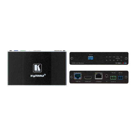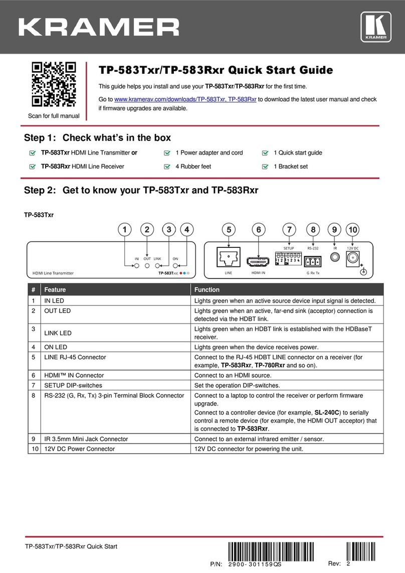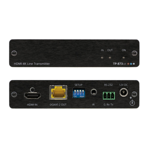
Lights green when an active source device input signal is detected.
Lights green when an active, far-end sink (acceptor) output signal is detected
via the HDBT link.
Lights green when the device receives power.
Connect to an HDMI acceptor.
DGKAT-2 IN RJ-45 Connector
Connect to the DGKAT 2 OUT RJ-45 connector on the TP 873xr
Set the operation DIP-switches (see Step 4: Connect the inputs and outputs).
IR 3.5mm Mini Jack Connector
Connect to an external infrared emitter / sensor for IR signal bidirectional
extension. For example, connect to an external infrared sensor to control the
HDMI IN source that is connected to TP 873xr.
RS-232 (G, Rx, Tx) 3-pin Terminal Block
Connector
Connect to a laptop to perform firmware upgrade or to an RS-232 port for serial
signal bidirectional extension to the transmitter. For example, connect to an
RS-232 device to be controlled, for example, a display.
12V DC connector for powering the unit when it is not powered by TP 873xr via
the DGKAT link.
Step 3: Mount TP-873xr/TP-874xr
Install TP-873xr/TP-874xr using one of the following methods:
•Attach the rubber feet and place the unit on a flat surface.
•Fasten a bracket (included) on each side of the unit and attach it to a flat surface
(see www.kramerav.com/downloads/TP-873xr).
•Mount the unit in a rack using the recommended rack adapter
(see www.kramerav.com/product/TP-873xr).
•Ensure that the environment (e.g., maximum ambient temperature &
air flow) is compatible for the device.
•Avoid uneven mechanical loading.
•Appropriate consideration of equipment nameplate ratings should be
used for avoiding overloading of the circuits.
•Reliable earthing of rack-mounted equipment should be maintained.
Step 4: Connect the inputs and outputs
Always switch OFF the power on each device before connecting it to your TP-873xr/TP-874xr.
To achieve specified extension distances, use the recommended Kramer cables available at www.kramerav.com/product/TP-873xr.
Using third-party cables may cause damage!


