SGM LEKTRA MUXM User manual

MUXM
multiplexer concentrator for TM and TU (pending) probes
technical documentation EN Rev. of 16/03/2022

Page 2 of 24 www.sgm-lektra.com
MUXM - contents
CONTENTS
1-WARRANTY
2-PRODUCT
3-FEATURES
4-DIMENSIONS
5-ELECTRICAL CONNECTIONS
6-VL701 DISPLAYING AND PROGRAMMING
7-CONFIGURATION
8-FACTORY TEST AND QUALITY CERTIFICATE
page 3
page 4
page 5
page 6
page 8
page 16
page 17
page 24

Page 3 of 24
www.sgm-lektra.eu
Products supplied by SGM LEKTRA are guaranteed for a period of 12 (twelve) months from delivery date according to the
conditions specifi ed in our sale conditions document.
SGM LEKTRA can choose to repair or replace the Product.
If the Product is repaired it will maintain the original term of guarantee, whereas if the Product is replaced it will have 12
(twelve) months of guarantee.
The warranty will be null if the Client modifi es, repair or uses the Products for other purposes than the normal conditions
foreseen by instructions or Contract.
In no circumstances shall SGM LEKTRA be liable for direct, indirect or consequential or other loss or damage whether
caused by negligence on the part of the company or its employees or otherwise howsoever arising out of defective goods
1-WARRANTY
MUXM - warranty

Page 4 of 24 www.sgm-lektra.com
MUXM - product
2- PRODUCT
3
2
1
1. “VL701” extractable module (optional) for displaying and programming
2. Terminals
3. Closing cover
2.1 IDENTIFICATION
Each instrument has an adhesive identication plate on which are the meter main data. The following picture describes the
information and data on the identication plate
MUXM02B
85÷230Vac 50÷60Hz
AB0123456789
2
3
1
1. Product code
2. Power supply
3. Serial number

Page 5 of 24
www.sgm-lektra.eu
3-FEATURES
MUXM
Concentrator for TM temperature probes and TU humidity probes (pending). Up to max. 32 TU+TM probes can be connected to
each MUXM. With 32 connected TM probes, and each probe with 50 temperature measuring points (highest possible option), the
total is 1600 controllable points. The electrical connection between the probe and the MUXM is made with a screened cable, while
the connection between the MUXM and the AGRITHERM-50 control unit is made with screened bipolar cable for data
communication via MODBUS RTU. The MUXM and the connected probes conguration is made via the VL701 removable module
and operations are displayed by the O-LED display. Up to 63 “MUXM” can be connected by MODBUS serial network.
Housing material
Aluminium
Installation
Wall mounting
Programming
Via VL701 removable module with display and 4 buttons (opt.)
Display
OLED display 57 x 30 digit alphanumeric
Electrical connections
4 removable terminals 4-pole probes for TM or TU
2 terminal. extr. 3-pin connection for Modbus
2 terminal. extr. 3-pin for supply voltage
Power supply
85 ÷ 230Vac 50 to 60Hz
Consumption
3.5 VA
Measuring inputs
No. 4 x 8 TM or TU probes
Conversion Resolution
0.1° C
Maximum expansion system
No. 63 MUXM
TM probes per MUXM unit
No. 32 maximum
Digital communications
MODBUS RTU
Operating temperature
-20 ° C to + 70 ° C
Ip rating
IP66
Ex-proof
ATEX Zone 22 self certication
MUXM - features

Page 6 of 24 www.sgm-lektra.com
MUXM - dimensions
4-DIMENSIONS
4.1 MECHANICAL DIMENSIONS
285~
210~
92,5
160
260

Page 7 of 24
www.sgm-lektra.eu
MUXM - dimensions
4.2 WALL MOUNTING
240mm
110mm
Ø7mm

Page 8 of 24 www.sgm-lektra.com
5.1 INSTALLATION PRECAUTIONS
- Installation shall only be performed by quali ed personnel and in accordance with local governing regulations.
- Make sure that the working temperature is between -20 and +70°C
- Install the concentrator in a its physical characteristics and housing construction materials compatible environment.
- The concentrator must be used safety warnings observance.
- Improper transmitter use would cause serious damage to people, to the product and connected equipment.
- Do not open the housing in the presence of potentially explosive dust
5-ELECTRICAL CONNECTIONS
MUXM - electrical connections
5.2 ADVICE FOR EXTERNAL MOUNTING
- for electrical connections, use a cable with a 6÷12mm outer diameter and fully tighten the M20x1.5 cable gland
- correctly close the cover, and fully tighten the screws.
- For connections between MUXM and TM use probes FUTP2PR AWG624/1 CAT. 5E cable
- position the cable so that it forms a downward curve at the cable glands output; in this way the condensation and/or rain water
will tend to drip from the bottom curve (as shown below).

Page 9 of 24
www.sgm-lektra.eu
MUXM - electrical connections
5.2.1 CABLES ENTRY/EXIT
M20x1.5
85÷230Vac power sup-
ply cable entry
M20x1.5
85÷230Vac power
supply cable entry
M20x1.5
MODBUS RTU
serial communication
cable entry
M20x1.5
MODBUS RTU
serial communication
cable entry
M20x1.5
Cable entry for TM probes
connecting to the
CH1 ÷ CH4 channels

Page 10 of 24 www.sgm-lektra.com
MUXM - electrical connections
5.2.1.1 Cable technical specications for the TM probes and MODBUS connection
FUTP2PR AWG6 24/1 CAT. 5E cable
Conductors copper rigid wire, Ø 0,50mm
Insulations Polyethylene, Ø 1,00mm +-0,1
Conductors Colours 2 white-green-brown
Wires twisted in pairs Green/white-brown/white
Twisting Twisted pairs between them
Shielding Polyester tape + tinned copper continuous wire + Mylar tape
Sheath BLUE PVC RZ RAL 5015 Ø 5,90mm+-0,50
Marking SGM-LEKTRA-525B025A-F UTP 2PR AWG 6 24/1 CAT 5E+metric mark
Operating temperature -25°C+70°C (xed installation)
Test voltage 1,5KV V.c.a.
Working voltage 300/300V
Curvature radius 8 times the diameter
Reference Standards CEI 20-35 - IEC 332.1 – CEI 20-37 ROHS 2011/65/UE(ROHS 2)

Page 11 of 24
www.sgm-lektra.eu
MUXM - electrical connections
5.3 CONNECTIONS
- Remove the cover by unscrewing the 4 screws and the caps from the cable glands used for connection
- Insert the power cable, the Modbus communication cable and the TM/TU probes cable by passing them through the
cable glands.
- Connect the cables to the appropriate terminals, as the following paragraphs.
- Fully tighten the cable gland and tightly close the MUXM cover to ensure the IP66 protection
MODBUS
port
85÷230Vac
power supply
TM or TU
probes input
85÷230Vac
power supply
MODBUS
port
L
N
B
A
SCH
L
N
B
A
SCH
CH1 CH2 CH3 CH4
ON
COM
+ B A
-+ B A
-+ B A
-+ B A
-

Page 12 of 24 www.sgm-lektra.com
MUXM - electrical connections - TM probe
5.3.1 Two or more (max.32) TM multipoint temperature probe Connection
For the electrical connection between the MUXM and TM temperature probe use the
FUTP2PR AWG624/1 CAT.5E cable (ns. Cod. 525B025A), or equivalent, suitable for data transmission.
The cable shield must only be connected to the next TM probe side; eg .: the shield of the connecting cable between the
TM2 probe and the TM3 probe should only be connected to the SCH terminal of the TM3 probe
At the work end:
a) Tighten all cable glands to ensure IP66 protection, for the concentrator MUXM, and IP67 for TM probe
b) Perform the procedure described in paragraph 7.6.3 (AUTO SETUP)
L
N
B
A
SCH
L
N
B
A
SCH
ON
COM
CH1 CH2 CH3 CH4
+ B A
-+ B A
-+ B A
-+ B A
-
B
A
+
-
SCH
B
A
+
-
SCH
B
A
+
-
SCH
TM 1 TM 8
5.3.1.1 Series connection (max. cable length 1200mt)

Page 13 of 24
www.sgm-lektra.eu
MUXM - electrical connections - TM probe
L
N
B
A
SCH
L
N
B
A
SCH
ON
COM
CH1 CH2 CH3 CH4
+ B A
-+ B A
-+ B A
-+ B A
-
B
A
+
-
SCH
B
A
+
-
SCH
B
A
+
-
SCH
TM 1 ..... .....TM 8
B
A
+
-
SCH
5.3.1.2 Star connection (Probe cable length max. 100mt)

Page 14 of 24 www.sgm-lektra.com
MUXM - electrical connections - AGRITHERM50
L
N
L
N
B
A
SCH
ON
COM
CH1
CH2
CH3
CH4
+ B A
-+ B A
-
+ B A
-+ B A
-
B
A
SCH
AGRITHERM50
S107 USB
USB
B
A
SCH
5.3.3 Connection to AGRITHERM50 (PC) via MODBUS
For the electrical connection between the MUXM and RS485/USB conversion module use the
FUTP2PR AWG624/1 CAT.5E cable (ns. Cod. 525B025A), or equivalent, suitable for serial data transmission
At the work end:
a) Tighten all cable glands to ensure IP66 protection

Page 15 of 24
www.sgm-lektra.eu
MUXM - electrical connections - MUXM network
L
N
L
N
B
A
SCH
ON
COM
CH1
CH2
CH3
CH4
+ B A
-+ B A
-
+ B A
-+ B A
-
B
A
SCH
AGRITHERM50
MUXM - UID 01
L
N
L
N
L
N
B
A
SCH
ON
COM
CH1
CH2
CH3
CH4
+ B A
-+ B A
-
+ B A
-+ B A
-
B
A
SCH
MUXM - UID 64
5.3.4 Connection of two or more “MUXM” in a single MODBUS RTU network
For the electrical connection between the “MUXM” of a MODBUS network use the
FUTP2PR AWG624/1 CAT.5E cable (ns. Cod. 525B025A), or equivalent, suitable for via RS485 data transmission
At the work end:
a) Tighten all cable glands to ensure IP66 protection

Page 16 of 24 www.sgm-lektra.com
MUXM - VL701
6- VL701
The VL701 display module is required to congure the MUXM. The VL701 module inserting or removing does not aect the MUXM
operation. The module VL701 can be inserted (through a clockwise rotation until it clicks) or removed (via counter-clockwise
rotation) as shown in below gure. The VL701 module mounts an OLED display, navigable by four buttons.
6.1VIA VL701 CONFIGURATION
The VL701 program module has 4 buttons which allow to perform all operational, control and programming instrument
functions.
In the conguration menus, is possible:
a) Submenus and parameters access; press to select and press to access.
b) Parameter options choice: Press to select the option and press to store the option. Press to exit without saving.
c) Congure the parameter values; in some parameters the conguration is done by setting a value (eg., in the NETWORK ID
parameter is possible to change the number): press to select the digit to be modied (the digit is highlighted in inverse),
press to change the highlighted digits number, press, to save the set value and exit automatically. Press to exit
without saving
LOCK UNLOCK
- Exit conguration
- Back to previous menu
- Parameters values modication
- Scroll cursor (to the right)
- Scroll parameters
- Conguration access
- Options conrmation
- Parameters values conrmation

Page 17 of 24
www.sgm-lektra.eu
MUXM - conguration
7- CONFIGURATION
7.1MENÙ - DISPLAY MEASURE
7.1.1 Menu structure
DISPLAY MEASURE CH1 1
CH2
CH3
P6 - 25.0
P7 - 25.3
P8 - 25.5
P9 - 25.6
P10 - 25.8
CH4
1
1
1
CH1-PROBEx
P1 - 25.4
P2 - 25.2
P3 - 25.3
P4 - 25.5
P5 - 25.0
PROBE
x
PROBE
x
PROBE
x
PROBE
x
P6 - 25.0
P7 - 25.3
P8 - 25.5
P9 - 25.6
P10 - 25.8
CH2-PROBEx
P1 - 25.4
P2 - 25.2
P3 - 25.3
P4 - 25.5
P5 - 25.0
P6 - 25.0
P7 - 25.3
P8 - 25.5
P9 - 25.6
P10 - 25.8
CH3-PROBEx
P1 - 25.4
P2 - 25.2
P3 - 25.3
P4 - 25.5
P5 - 25.0
P6 - 25.0
P7 - 25.3
P8 - 25.5
P9 - 25.6
P10 - 25.8
CH4-PROBEx
P1 - 25.4
P2 - 25.2
P3 - 25.3
P4 - 25.5
P5 - 25.0
P46 - 25.0
P47 - 25.3
P48 - 25.5
P49 - 25.6
P50 - 25.8
CH1-PROBEx
P41 - 25.4
P42 - 25.2
P43 - 25.3
P44 - 25.5
P45 - 25.0
P46 - 25.0
P47 - 25.3
P48 - 25.5
P49 - 25.6
P50 - 25.8
CH2-PROBEx
P41 - 25.4
P42 - 25.2
P43 - 25.3
P44 - 25.5
P45 - 25.0
P46 - 25.0
P47 - 25.3
P48 - 25.5
P49 - 25.6
P50 - 25.8
CH3-PROBEx
P41 - 25.4
P42 - 25.2
P43 - 25.3
P44 - 25.5
P45 - 25.0
P46 - 25.0
P47 - 25.3
P48 - 25.5
P49 - 25.6
P50 - 25.8
CH4-PROBEx
P41 - 25.4
P42 - 25.2
P43 - 25.3
P44 - 25.5
P45 - 25.0
UID n. 1
DISPLAY MEASURE SERVICE
MODBUS SETUP
SYSTEM SETUP
FACTORY SETUP
INFO
To enter the menu DISPLAY MEASURE press The temperature read by the individual
measuring points of individual probes TM can be displayed in this menu
DISPLAY MEASURE
CH1
CH2
CH3
CH4
Select the parameters by moving the cursor with and conrm with .
7.1.2 DISPLAY MEASURE - Conguration Details

Page 18 of 24 www.sgm-lektra.com
MUXM - conguration
Position the sul canale (CH1 ÷ CH4) cursor to the channel (CH1 ÷ CH4) where
the probes are connected and press
DISPLAY MEASURE
CH1
CH2
CH3
CH4
Press to select the “TM” probe number to be monitored and press to display the
measured temperatures by the individual measuring points
PROBE
1
The temperatures measured by the rst ten measurement points of the selected sensor are
displayed. The number one measuring point (P01) is always positioned near the head of the
TM probe. Push to pass to the next page (only available when the TM probe has more
than 10 points) and view points from 11 to 20, from 21 to 30, etc. Press to exit.
CH1 - PROBE1
P01 24.1 P06 24.3
P02 24.1 P07 24.3
P03 24.1 P08 24.3
P04 24.1 P09 24.3
P05 24.1 P10 24.3
CH1 - PROBE1
P11 24.1 P16 24.3
P12 24.1
P13 24.1
P14 24.1
P15 24.1
7.1.3 CH1÷4

Page 19 of 24
www.sgm-lektra.eu
MUXM - conguration
7.2MENÙ - SERVICE
7.2.1 Menu structure
COM TEST
CH1÷4 PROBES
CH1
CH2
CH3
CH4
SERVICE
12345678
1: TM_ 12
2: TM_ 10
3: TM_ 10
4: TM_ 10
5: TM_ 12
6: TM_ 10
7: TM_ 10
8: TM_ 10
COM TEST
CH1÷4 PROBES
7.2.2 SERVICE - Conguration details
UID n. 1
DISPLAY MEASURE SERVICE
MODBUS SETUP
SYSTEM SETUP
FACTORY SETUP
INFO
Position the cursor on SERVICE with , press to enter.
SERVICE
COM TEST
CH1
CH2
CH3
CH4
Select the function by moving the cursor with “S” and conrm with
Position the cursor on COM TEST with , press to enter. SERVICE
COM TEST
CH1
CH2
CH3
CH4
The page displays how many probes are connected and communicate to the individual CHx
channels. The complete view of the data communication status between MUXM and TM probes
is possible with the “TEST COM”; see the next example: 8 TM probes are connected to the CH3
channel, but the TM4 probe does not communicate. Press to exit.
COM TEST
1 2 3 4 5 6 7 8
CH1
CH2
CH3
CH4
7.2.3 COM TEST
Position the cursor on CHx and press . SERVICE
COM TEST
CH1
CH2
CH3
CH4
The probes congured with the parameter “AUTO SETUP” (see par. 6.4.3) is displayed, for each
individual channel CHx, with their number of measurement points; see eg. next: in the CH1
channel are congured 8 TM probes; the message “1: TM_12” means that the number 1 TM
probe has 12 measuring points; the message “2: TM_10” means that the number 2 TM probe
has 10 measuring points, etc. Press to exit.
7.2.4 CH1 ÷ 4
CH1 PROBES
1: TM_12 5: TM_10
2: TM_10 6: TM_10
3: TM_10 7: TM_10
4: TM_10 8: TM_12
x

Page 20 of 24 www.sgm-lektra.com
MUXM - conguration
7.3MENÙ - MODBUS
7.3.1 Menu structure
7.3.2 MODBUS - Conguration details
UID n. 1
DISPLAY MEASURE SERVICE
MODBUS SETUP
SYSTEM SETUP
FACTORY SETUP
INFO
Position the cursor on MODBUS SETUP with , press to enter
The security password is required to access the settings.
Use and to modify the value. Press to conrm. to exit without changes
Default password: 1000 Aer password conrming, access to the MODBUS port
parameters conguration is possible
Position the cursor on NETWORK ID with , press to enter.
This parameter gives the UID address for data communication in a MODBUS RTU network
Use and to modify the value. Press to conrm. to exit without changes
7.3.3 NETWORK ID
Position the cursor on BAUD RATE with , press to enter
This parameter sets the MODBUS port baud rate.
With select the boud rate value.
Press to conrm. to exit without changes
Default value: 19200
7.3.4 BAUD RATE
BAUD RATE
9600
19200
38400
56000
57600
115200
MODBUS NETWORK ID
BAUD RATE
STOP BIT
PARITY
PASSWORD ID
01
BAUDRATE
19200
PARITY
NONE
STOP BIT
1
PASSWORD
0000
MODBUS
NETWORK ID
BAUD RATE
PARITY
STOP BITS
NETWORK ID
001
MODBUS
NETWORK ID
BAUD RATE
PARITY
STOP BITS
Table of contents
Other SGM LEKTRA Measuring Instrument manuals

SGM LEKTRA
SGM LEKTRA Pmag User manual
SGM LEKTRA
SGM LEKTRA Transit Time SGM-200H Guide
SGM LEKTRA
SGM LEKTRA SGM-101H Guide

SGM LEKTRA
SGM LEKTRA SGM-100F User manual

SGM LEKTRA
SGM LEKTRA RPmag Guide
SGM LEKTRA
SGM LEKTRA FLOWMETER User manual

SGM LEKTRA
SGM LEKTRA RPmag Guide
SGM LEKTRA
SGM LEKTRA SGM-101F Guide
Popular Measuring Instrument manuals by other brands

Chino
Chino IM Series instructions
Omega
Omega HHWT-11 user guide
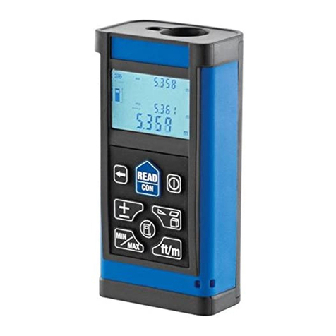
MasterCraft
MasterCraft LASER DISTANCE FINDER/MEASURING TOOL instruction manual
iDigit
iDigit A570 Ambient Monitor instruction manual
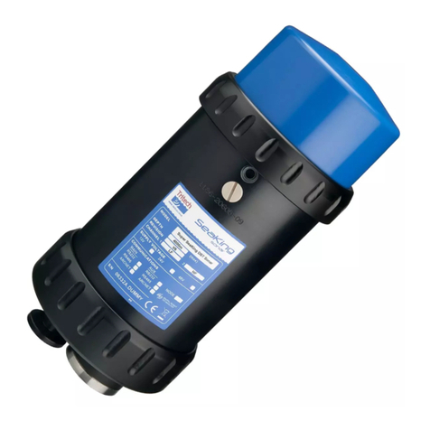
Tritec
Tritec SeaKing Profiling Sonar product manual
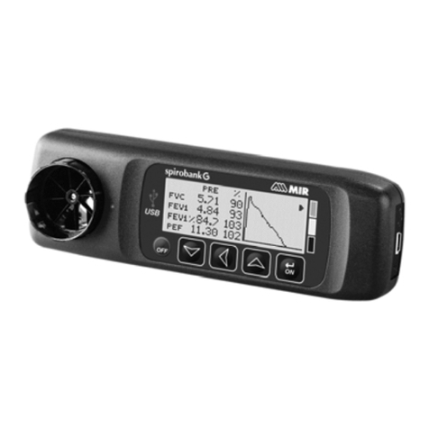
Medical International Research
Medical International Research spirobank G user manual

