SGM LEKTRA RPmag Guide
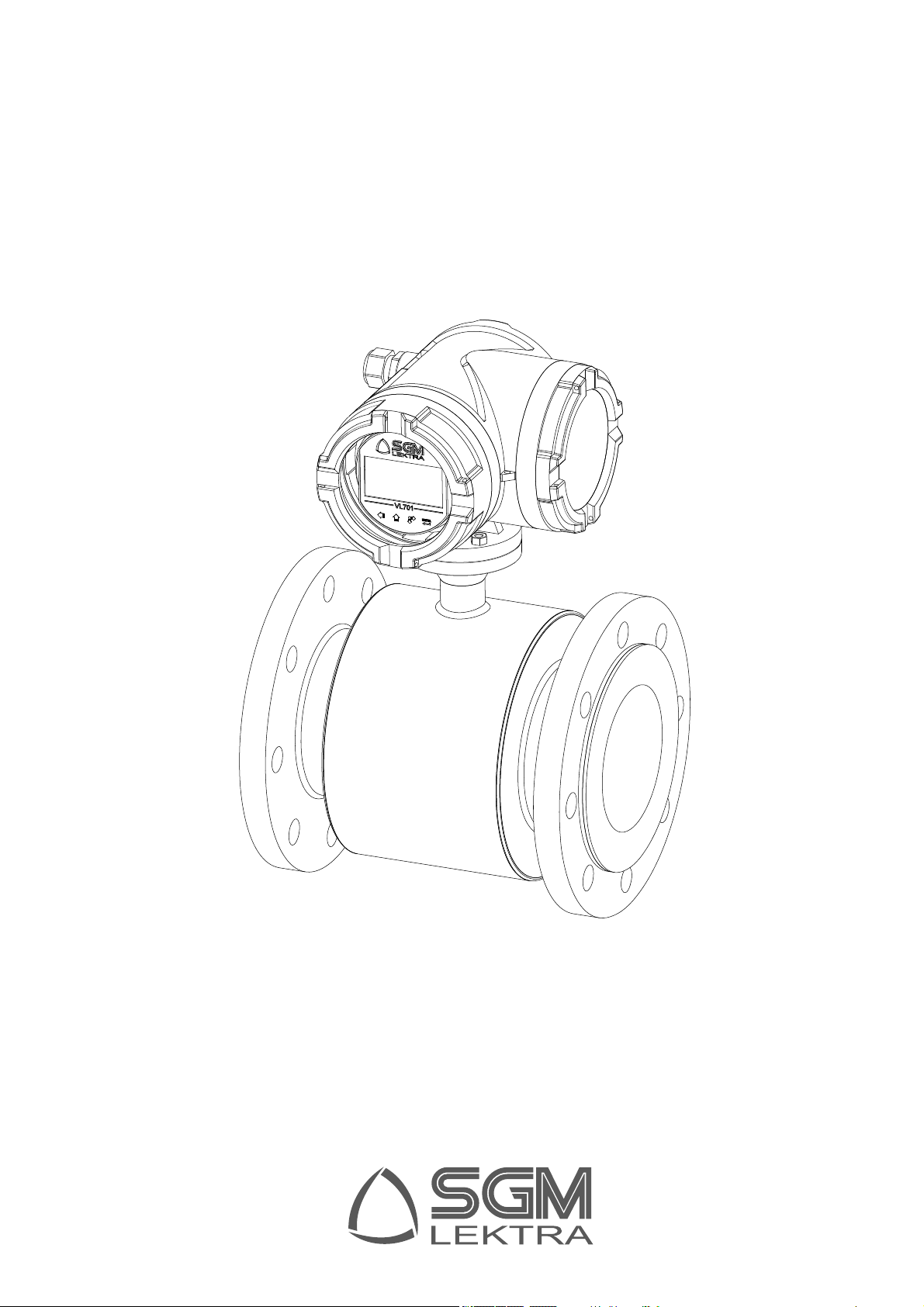
RPmag
electromagnetic induction fl ow measurement with data logger
technical documentation EN Rev. C

Page 2 of 64 www.sgm-lektra.com
RPmag - contents
CONTENTS
1-WARRANTY
2-CALIBRATION CERTIFICATE
3-PRODUCT
4-PERFORMANCE SPECIFICATIONS
5-FLOW RANGE
6-DIMENSION
7-INSTALLATION
8-ELECTRICAL CONNECTIONS
9-LOCAL OPERATOR INTERFACE (LOI)
10-PROGRAMMING
11-TROUBLESHOOTING
12-FACTORY TEST AND QUALITY CERTIFICATE
pag. 3
pag. 3
pag. 4
pag. 5
pag. 6
pag. 8
pag. 13
pag. 21
pag. 31
pag. 35
pag. 61
pag. 64

Page 3 of 64
www.sgm-lektra.eu
2-CALIBRATION CERTIFICATE
All the electromagnetic fl owmeter are tested by 3 point rigs calibration.
The producer releases a document on letterhead certifying the average error of the 3-point calibration.
The calibration certifi cate is supplied with the unit.
The company archives the test data of each electromagnetic fl owmeter.
The calibration rig is certifi cated by N.I.M. (National Institute of Metrology), which is internationally recognizedby B.I.P.M.
(Bureau International des Poids et Metrologie) and complies with NTC ISO IEC 17025 standard.
All calibrations are made in accordance to EN 45001 standards and with an accuracy better than 99.97%
RPmag - warranty / calibration certifi cate
Products supplied by SGM LEKTRA are guaranteed for a period of 12 (twelve) months from delivery date according to
the conditions specifi ed in our sale conditions document.
SGM LEKTRA can choose to repair or replace the Product.
If the Product is repaired it will maintain the original warranty terms, whereas if the Product is replaced it will have 12
(twelve) months of warranty.
The warranty will be null if the Client modifi es, repair or uses the Products for other purposes than the normal conditions
foreseen by instructions or Contract.
In no circumstances shall SGM LEKTRA be liable for direct, indirect or consequential or other loss or damage whether
caused by negligence on the part of the company or its employees or otherwise howsoever arising out of defective goods
1-WARRANTY
Page 4 of 64 www.sgm-lektra.com
RPmag - features
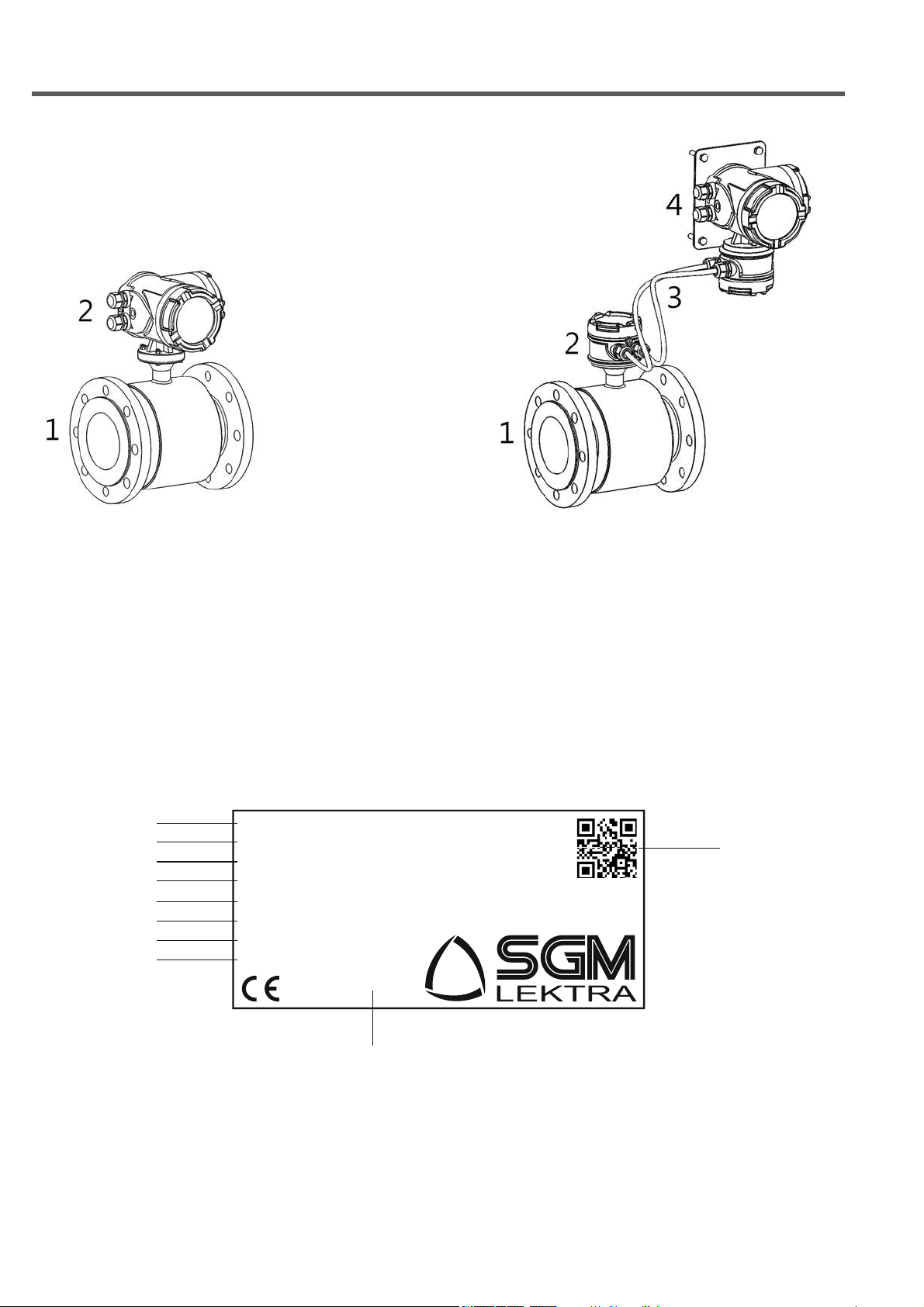
3- PRODUCT
COMPACT VERSION
1. Sensor
2. Converter
REMOTE VERSION
1. Sensor
2. Connection housing
3. Connection cables
4. Converter, wall mouting
3.1 IDENTIFICATION
Each meter has an adhesive identifi cation plate on which are the meter main data. The following picture describes the
information and data on the identifi cation plate.
1. Product code
2. Serial number
3. Production batch
4. Power supply
9. Protection
10.QR code, connecting a
product web page
5. Process connection
6. Lining material
7. Electrodes material
8. Sensor factor
Model
Serial n°
Meter n°
P.Supply
Connection
Lining
Electrode
Sens. Factor
RPMAGN0032B2B1A0A1
FM005141720
032377
85
÷
265Vac 50
÷
60Hz
DN32 PN40
RUBBER
SS316
0.2293
IP67

Page 5 of 64
www.sgm-lektra.eu
4-FEATURES
RPmag - features
Flow rate range
RPmag is able to process signals from fl uids with fl ow rates of up to 10m / s in both directions (bidirectional meter).
Range dimension / lining material
PTFE DN10 ÷ DN500 / RUBBER DN65 ÷ DN2000
Sensor material
SS321
Housing material
epoxy painting aluminium
Electrodes material
SS316L - Hastelloy C - Titanium - Tantalum - Platinum
Measure range
<0,1m3/h ÷ >110000m3/h
Accuracy
±0,5% standard; ±0,2% optional
Repeatability
±0,1%
Fluid conductivity
>5μS/cm.
Power supply
85÷265Vac, 24Vac/dc, 12Vdc.
Consumption
6W, max. 8W.
Ambient Temperature Limits
Remote version operating temperature: RUBBER -10 ÷ +80°C; PTFE -40 ÷ +150°C
Compact version operating temperature: RUBBER -10 ÷ +80°C; PTFE -40 ÷ +100°C
Storage temperature: -40÷85°C
Communication protocol
Modbus RTU or Bluetooth App Android (opt.) or Hart (opt.)
Data Logger
Internal data logger to USB pen drive for fl ow measurements and analog inputs storing;
the measurement storage interval can be set from 15 to 3600 seconds
Output
4÷20mA: 0÷500Ω
Frequency output: 0,1÷10000 Hz
Pulse output: 24Vdc galvanically isolated or open collector galvanically
isolated 24V 20mA (opt)
Alarm output: 2 relays, 3A 230Vac N.O.
Input signals
RPmag has 2 active analog inputs at 24Vdc for 2-wire transmitters connection (eg. Temperature or
pressure) and 1 digital input for an external contact connection for the integrated batch function restart and for
partial totalizer management.
Reverse Flow
Allows measure and totalization of reverse fl ow.
Output Testing
Relays output: Transmitter can switch relays at testing value.
Current Source: Transmitter can be commanded to supply a specifi ed test current between 4.0 and 20.0 mA.
Frequency Source: Transmitter can be commanded to supply a specifi ed test frequency between 1 and 10000 Hz.
Low Flow Cutoff
Adjustable. Below selected value, instantaneous fl ow and outputs are driven to the zero fl ow rate signal level.
Humidity Limits
0-100% RH to 150 °F (65 °C), not condensing.
Damping
Adjustable between 1 and 99 seconds.
Compact version IP rating
IP67
Remote version IP rating
sensor IP67 / IP68 (by request) - converter IP67
Anti-condensation fi lter
Anti-condensation fi lter installed on converter
Page 6 of 64 www.sgm-lektra.com
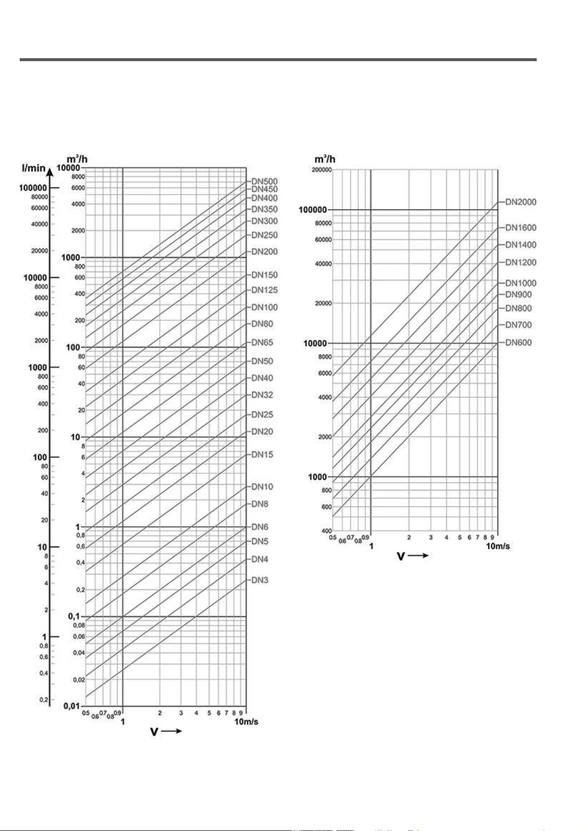
5-FLOW RANGE
RPmag - fl ow range
5.1 FLOW RANGE GRAPHIC
Flow range from DN3 to DN500 (starting from DN10) Flow range from DN600 to DN2000

Page 7 of 64
www.sgm-lektra.eu
RPmag - fl ow range
5.2 FLOW RANGE TABLES
5.3 LOAD LOSS
Adaptation cones
DN10 ÷ 300
DN
(mm)
Range: Minimum (0,5 m/s) /
Maximum (10 m/s)
10 0.14 ÷ 2.9 m3/h
15 0.3 ÷ 6 m3/h
20 0.5 ÷ 12 m3/h
25 0.6 ÷ 18 m3/h
32 1 ÷ 30 m3/h
40 1.8 ÷ 42 m3/h
50 3 ÷ 66 m3/h
65 5.8 ÷ 120 m3/h
80 8.9 ÷ 180 m3/h
100 11 ÷ 282 m3/h
125 20 ÷ 450 m3/h
150 30 ÷ 600 m3/h
200 50 ÷ 1100 m3/h
250 85 ÷ 1700 m3/h
300 110 ÷ 2400 m3/h
DN350 ÷ 2000
DN
(mm)
Range: Minimum (0,5 m/s) /
Maximum (10 m/s)
350 180 ÷ 3300 m3/h
400 220 ÷ 4200 m3/h
450 270 ÷ 5400 m3/h
500 320 ÷ 6600 m3/h
600 490 ÷ 9600 m3/h
700 680 ÷ 13500 m3/h
800 900 ÷ 18000 m3/h
900 1200 ÷ 22500 m3/h
1000 1450 ÷ 28000 m3/h
1200 2500 ÷ 40000 m3/h
1400 3000 ÷ 55000 m3/h
1600 4000 ÷ 70000 m3/h
1800 5000 ÷ 90000 m3/h
2000 6000 ÷ 110000 m3/h

Page 8 of 64 www.sgm-lektra.com
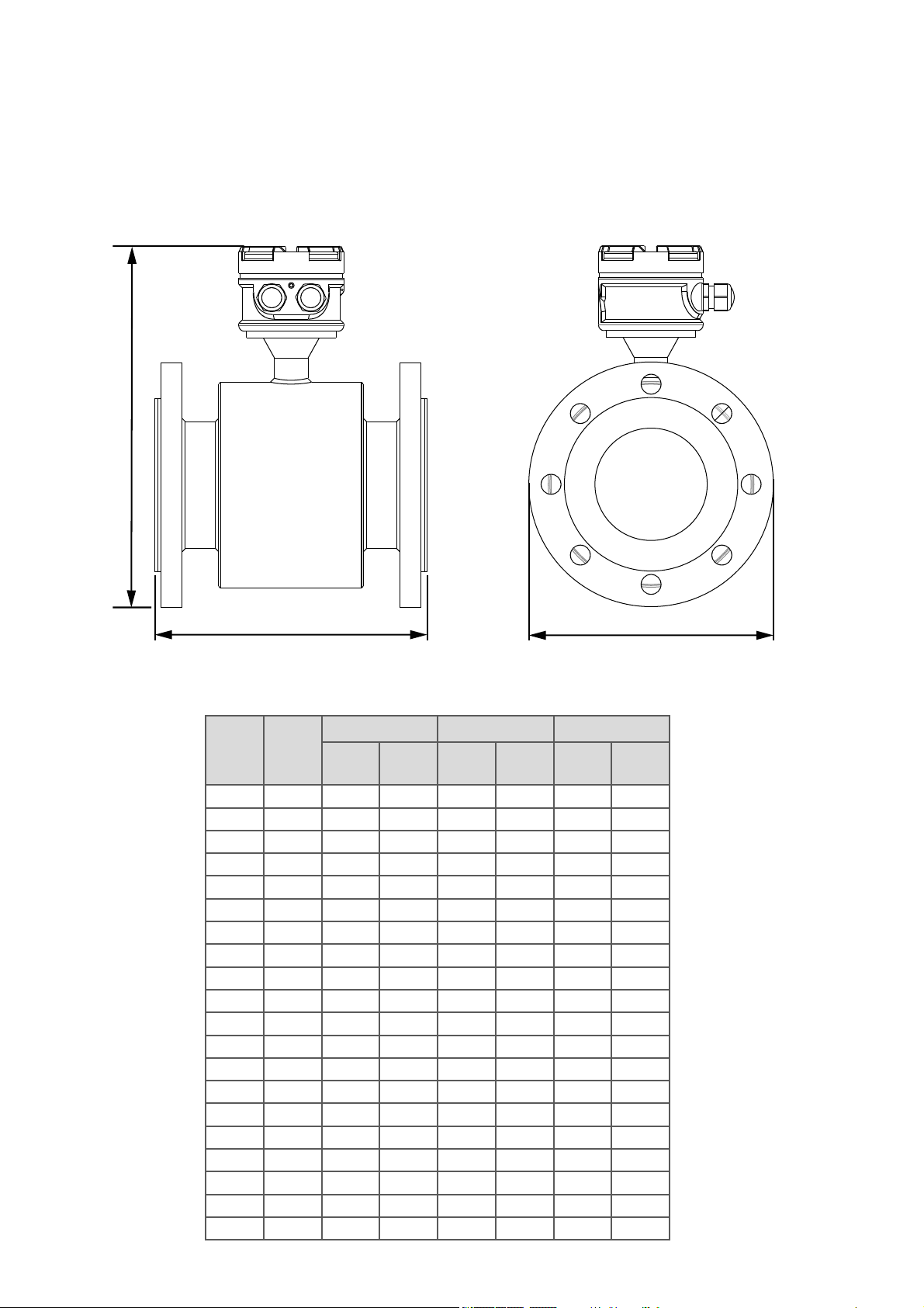
RPmag - dimensions
6-DIMENSIONS
6.1 REMOTE VERSION CONVERTER
215,5 mm
177 mm 170 mm
6.2 WALL MOUNTING REMOTE VERSION CONVERTER
150 mm
110 mm
Page 9 of 64
www.sgm-lektra.eu
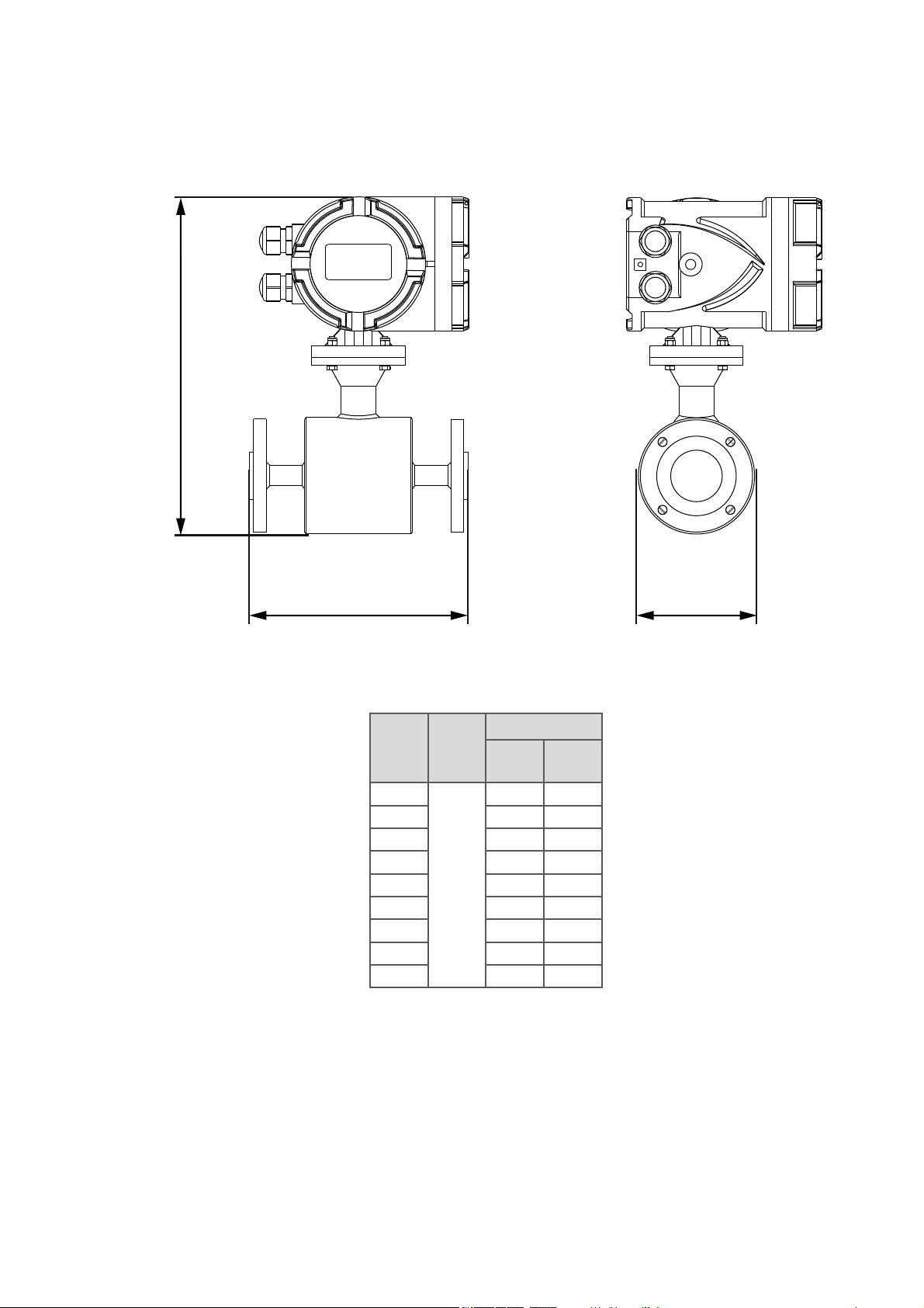
6.3 COMPACT VERSION DN10 ÷ DN80 PN16 - PN40
RPmag - dimensions
DN
(mm)
A
(mm)
PN 16 - PN 40
B
(mm)
ØD
(mm)
10
200
295 90
15 295 95
20 300 105
25 300 115
32 315 140
40 335 150
50 344 165
65 360 185
80 375 200
A
B
Ø D

Page 10 of 64 www.sgm-lektra.com
RPmag - dimensions
6.4 COMPACT VERSION DN100 ÷ DN1000 PN10 - PN16 - PN40
A
B
Ø D
DN
(mm)
A
(mm)
PN 10 PN 16 PN 40
B
(mm)
ØD
(mm)
B
(mm)
ØD
(mm)
B
(mm)
ØD
(mm)
100 250 - - 400 220 410 235
125 250 - - 420 250 435 270
150 300 - - 460 285 468 300
200 350 520 340 520 340 538 375
250 450 570 395 575 405 598 450
300 500 620 445 620 460 648 515
350 550 670 505 678 520 708 580
400 600 730 565 738 580 778 660
450 600 780 615 793 640 816 685
500 600 830 670 850 715 870 755
600 600 930 780 960 840 985 890
700 700 1050 895 1080 910 - -
800 800 1165 1015 1170 1025 - -
900 900 1270 1115 1275 1125 - -
1000 1000 1360 1230 1375 1255 - -

Page 11 of 64
www.sgm-lektra.eu
RPmag - dimensions
6.5 REMOTE VERSION DN10 ÷ DN25 PN16 - PN40
DN
(mm) A
(mm)
PN 16 - PN 40
B
(mm)
ØD
(mm)
10
200
235 90
15 235 95
20 240 105
25 240 115
A
B
Ø D
Page 12 of 64 www.sgm-lektra.com
RPmag - dimensions
6.6 REMOTE VERSION DN32 ÷ DN1000 PN10 - PN16 - PN40
A
B
Ø D
DN
(mm)
A
(mm)
PN 10 PN 16 PN 40
B
(mm)
ØD
(mm)
B
(mm)
ØD
(mm)
B
(mm)
ØD
(mm)
32 200 - - 251 140 254 140
40 200 - - 270 150 270 150
50 200 - - 280 165 280 165
65 200 - - 298 185 298 185
80 200 - - 315 200 315 200
100 250 - - 333 220 343 235
125 250 - - 358 250 368 270
150 300 - - 393 285 400 300
200 350 450 340 450 340 468 375
250 450 505 395 510 405 533 450
300 500 550 445 558 460 586 515
350 550 605 505 613 520 643 580
400 600 665 565 673 580 713 660
450 600 715 615 728 640 751 685
500 600 765 670 785 715 805 755
600 600 870 780 900 840 810 890
700 700 987 895 995 910 - -
800 800 1100 1015 1105 1025 - -
900 900 1202 1115 1207 1125 - -
1000 1000 1293 1230 1306 1255 - -

Page 13 of 64
www.sgm-lektra.eu
7-INSTALLATION
7.1 SAFETY MEASURE
Instructions and procedures in this section may require special precautions to ensure the safety of the personnel per
forming the operations. Information that raises potential safety issues is indicated by a warning symbol . Please refer
to the following safety messages before performing an operation preceded by this symbol.
7.2 WARNINGS
7.2.1 Explosions could result in death or serious injury
- Verify that the operating atmosphere of the sensor pipe and transmitter is consisten with the appropriate hazardous
locations certifi cations.
- Do not remove the transmitter cover in explosive atmospheres when the circuit is alive.
7.2.2 Failure to follow safe installation and servicing guidelines could result in death ors
eriousinjury
- Make sure only qualifi ed personnel perform the installation.
- Do not perform any service other than those contained in this manual unless qualifi ed.
7.2.3 High voltage that may be present on leads could cause electrical shock
- Avoid contact with leads and terminals.
7.3 PRE-INSTALLATION
There are several pre-installation steps that make the installation process easier. They include identifying the options
and confi gurations that apply to your application, setting the hardware switches if necessary, and consideration of
mechanical, electrical, and environmental requirements. Please remember that the sensor pipe liner is vulnerable to
handling damage. Never place anything through the sensor pipe for the purpose of lifting or gaining leverage. Damaged
liner can render the sensor pipe useless.
7.3.1 Identify Options and Confi gurations
Standard application of the RPmag includes control of the sensor pipe coils and one or more of the following con
fi gurations or options:
- 4÷20mA output
- Pulse output
- Alarm output
- Data logger
Be sure to identify the options and confi gurations that apply to your situation, and keep a list of them nearby during
the installation and confi guration procedures.
7.3.2 Mechanical Considerations
The mounting site for the RPmag Integral Mount Transmitter should provide enough room for secure mounting,
easy access to the conduit ports, full opening of the transmitter covers, and easy readability of the local operator
interface (LOI) screen.The LOI can be rotated in 90° increments.
7.3.3 Lift
The fl owmeter can be lifted using the lift as shown in following pictures. The safe load and measure for the lift
should reach to the relative requirement. Don’t lift the fl owmeter using the rope to tie the connection between
the sensor and the transmitter (compact version) or the connecting box (remote version)
RPmag - installation
Page 14 of 64 www.sgm-lektra.com
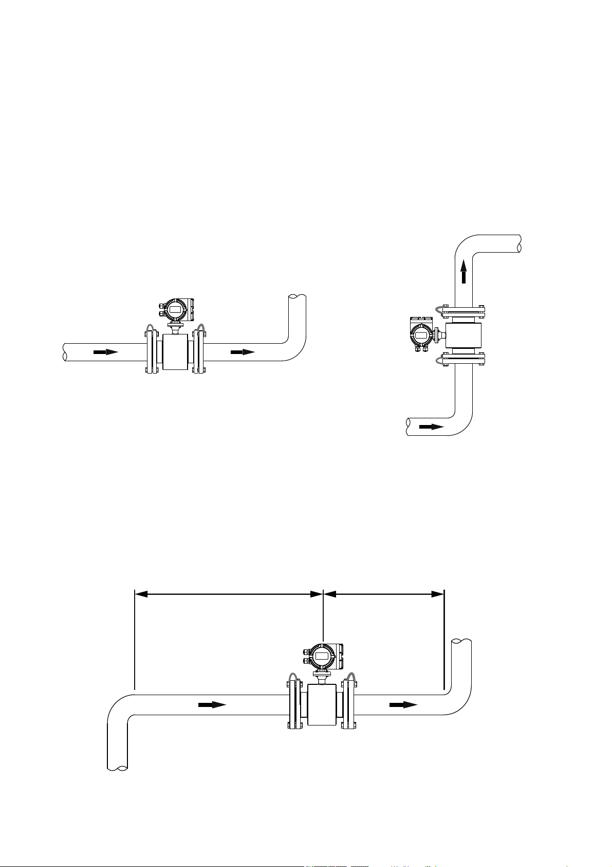
7.4 INSTALLATION GENERAL CRITERIA
The fl owmeter can test automatically fl ow direction. Because the direction arrow marked on the nameplate is fl ow
direction when calibrated in factory, you should install the fl owmeter to make the actual fl ow direction same as the fl ow
direction arrow marked on the nameplate. If this is not possible, simply reverse the direct fl ow direction through the
“Indication” (see par. 10.4.3.4.1)
The upstream straight pipe should be longer than 5XDN and the downstream straight pipe should be more than 3XDN
in order to guarantee the accuracy of measurement.
7.5 INSTALLATION IN PIPELINE
Installation may be horizontal or vertical, but make sure no deposit on the electrodes when horizontal installation.
See Fig.13-A.
Fig.13-A. Installation in horizontal or vertical pipeline
To install an rectifi er or straight pipe is necessary to normalize the fl ow profi le if there are pipe elbow, fl ow regulation
valve or half-open ball valve in front of the sensor. See fi g.13-B.
Fig.13-B. Requirement to install the fl owmeter straight pipes
5 x DN 3 x DN
RPmag - installation

Page 15 of 64
www.sgm-lektra.eu
Fig.14-A Installation in partially fi lled pipes
The electromagnetic fl owmeter must be installed so that the pipe is always completely fi lled with fl uid. In partially fi lled
pipe case, the fl owmeter must be installed with the siphon phenomenon, for which the pipe stretch where the meter is
installed is kept always full. See Fig.14-A.
The electromagnetic fl owmeter must not be installed in the pipe section with a free pipe outlet that could run empty.
When installating in a downstream pipe, please make sure the pipe is always fully fi lled with medium
See Fig.14-B
Fig.14-B Installation in pipe without emptying
RPmag - installation
5 x DN 2 x DN
2 x DN

Page 16 of 64 www.sgm-lektra.com
The electromagnetic fl owmeter can not be installed at the pipe highest point, because air or gas accumulations may
occur in the measuring pipe. See Fig.15-A
Fig.15-A Installation at highest point
The electromagnetic fl owmeter can not be installed upstream of a pump to prevent cavitation, which can damage the
sensor lining. See Fig.15-B
Fig.15-B Pump proximity installation
Fig.15-C Installation in proximity of a > 5m down pipe section
RPmag - installation
>5 mt
b
a
Install a siphon (a) with a vent valve (b) downstream of the sensor in down pipes longer than 5 meters. This precaution
is to avoid low pressure and the consequent risk of damage to the lining of the measuring tube. See Fig.15-C
WARNING: all the phenomena that generate a strong depression inside the pipe can irremediably damage the insulating
coating of the sensor tube itself.

Page 17 of 64
www.sgm-lektra.eu
7.6 INSTALLATION PRECAUTIONS
An all-weather cover should be used to prevent the housing from the direct sunlight or rain when the device in outdoors
The fl owmeter should the excessive vibrations, large ambient temperature changing and long-time shower. It should
be prevent from the leakage of the corrosive liquid.
7.7 PIPE CONNECTION
The sensor should be supported by the connecting pipes, it cannot withstand its own weight.
Mechanical and thermal stress must be avoided.
RPmag - installation
>10 mt

Page 18 of 64 www.sgm-lektra.com
7.8 MOUNTING REQUIREMENTS
a) The sensor pipe and the line pipes must have the same axis. For the sensors under DN50, the axial diff erence
between the measuring tube and operating pipe should be less than 1.5mm; for the sensors from DN65 to DN300,
it should be less than 2mm; for the sensor over DN350, it should be less than 4mm.
b) The gasket between fl anges should have a good corrosive resistance. The gasket must not extend to the pipe
inside.
c) The threads of the fasten bolts and nuts should be in good condition. The bolts should be fastened using torque
spanner with certain torque according the size of fl ange.
d) It should take separate measure to prevent the lining from heat when weld or fl ame cutting in the pipe closed to
sensor. If the sensor is installed in a well or immersed in water, the connecting box for sensor must be fi lled
and sealed with sealing glue after commissioning.
7.9 ACCESSORIES
7.9.1 Grounding ring optional
Material: SS 316L or Hastelloy C
Thickness: 3mm for SS 316L or 1mm for Hastelloy C
For the non-conductive pipe, the grounding rings should be installed between the fl anges of sensor and pipe to make
the fl owmeter and measured medium at same potential.
Grounding ring
RPmag - installation
Ø6mm 3mm AISI316L
1mm Hastelloy C
Page 19 of 64
www.sgm-lektra.eu
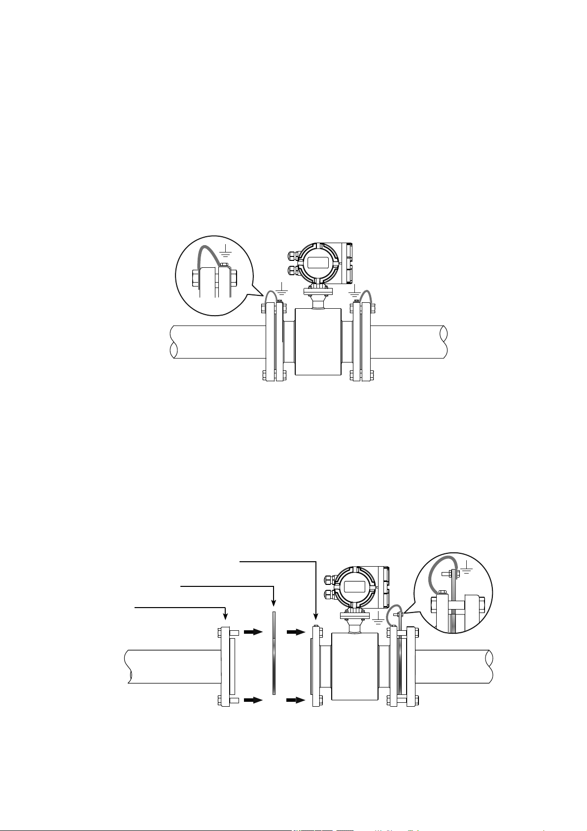
Fig.18B Grounding with non-conductive pipes
7.10 EQUIPOTENTIALITY AND ELECTRICAL INTERFERENCE REDUCTION
The measuring circuit assumes the fl uid at ground potential, as it is in most of application with conductive pipes.
The sensor is isolated from the fl uid because of the lining, therefore it’s necessary to connect the grounding cables to
the pipe’s fl anges, as shown in fi g. 18-A. The resistance for grounding connection should be less than 10ohm.
Most of application do not require special precautions for installation, the only requirement is to keep the signal cable
separate from the main cable. In case of sensor with cathodic protection or electrolysis processes, the main current
shall not fl ow through the measured fl uid..
The following measure should be taken in order to reduce the infl uence of magnetic fi eld:
a) With conductive pipes, potential equalization is made by connecting sensor and the adjoining pipes as shown in
fi gure. The bolt connection for fl anges can not be used instead of the electric connection, it must have an additional
electric connection as shown in Fig.18A.
RPmag - installation
Non-conductive pipes
Grounding Ring
SS316 Sensor
Fig.18A Sensor equipotentiality
b) For the non-inductive pipe, the grounding rings should be installed between the both fl anges for sensor and the
both fl anges for pipe. See Fig.18B.
Page 20 of 64 www.sgm-lektra.com
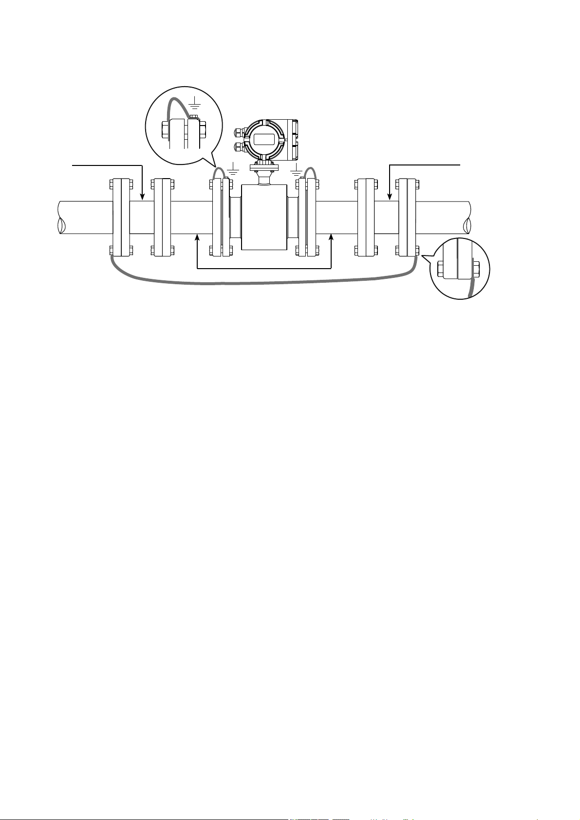
Fig.19A Pipe segmentation
Rubber Pipe
Rubber Pipe
7.11 PREPARATION FOR OPERATION
Strictly check the instalment and wirings before it gets into operation!
It shall be pointed out that the instrument, including the sensor and converter has been fully adjusted, calibrated
with actual fl ow, and inspected under strict measures. All the units are certifi ed. No further adjustments are
required when put it into operation. Observing the contents in this manual, to check and analyze any malfunction
The following steps are to be followed to get the instrument into operation.
1) Make sure that the sensor is completely fi lled with fl uid.
2) Turn the power supply ON. After approx. one minute, the display will show a value which indicates that the
wire connection is correct. If the fl ow value is negative, it can be adjusted
3) Zero verifi cation. Shut off the valve tight in downstream fi rst and then the valve in upstream,
to let the liquid stops to fl ow in the pipeline. The displayed value should be 0. The value displayed can be
corrected at the converter if the value is diff erent than 0.
7.12 MAINTENANCE
Generally, no extraordinary maintenance is needed on magnetic fl owmeter.
Only in case the product can adhere to the inner wall of the sensor, and its electrodes, it is necessary to perform
periodic cleaning operations.
Be careful not to damage the lining and the electrodes.
SS316 Pipe
RPmag - installation
c) Some systems, such as pipes with cathodic protection, may be aff ected by potential disturbance because not all the
line is at ground potential. In order to eliminate this type of interference, it must be isolate the line with two rubber
pipes as shown in Fig.19A.
Other manuals for RPmag
1
Table of contents
Other SGM LEKTRA Measuring Instrument manuals

SGM LEKTRA
SGM LEKTRA RPmag Guide

SGM LEKTRA
SGM LEKTRA SGM-101H Guide

SGM LEKTRA
SGM LEKTRA SGM-101F Guide

SGM LEKTRA
SGM LEKTRA SGM-100F User manual

SGM LEKTRA
SGM LEKTRA MUXM User manual

SGM LEKTRA
SGM LEKTRA FLOWMETER User manual

SGM LEKTRA
SGM LEKTRA Pmag User manual

SGM LEKTRA
SGM LEKTRA Transit Time SGM-200H Guide
Popular Measuring Instrument manuals by other brands


Hilti
Hilti pos 150 Original operating instructions

PCB Piezotronics
PCB Piezotronics 350B01 Installation and operating manual

Hanna Instruments
Hanna Instruments Checker HI707 instruction manual

Curtiss-Wright
Curtiss-Wright SSR/CHS/001 manual

Neutronics
Neutronics YELLOW JACKET 68945 Operation manual

Vaisala
Vaisala WAA251 Quick reference guide


