SGM LEKTRA Transit Time SGM-200H Guide
SGM-200H
“transit time” ultrasonic flow meter
GB technical documentation Rev. D

Page 2 di 32 www.sgm-lektra.com
SGM-200H - table of contents
TABLE OF CONTENTS
1-WARRANTY
2-PRODUCT
3-TECHNICAL SPECIFICATIONS
4-DIMENSIONS
5-INSTRUMENT PARAMETERS
6-DESCRIPTION OF MAIN PARAMETERS
7-INSTALLATION
8-USE
9-TESTING AND QUALITY CERTIFICATE
page 3
page 4
page 6
page 7
page 11
page 12
page 15
page 28
page 32

Page 3 di 32
www.sgm-lektra.eu
SGM-200H - warranty
SGM LEKTRA S.R.L. undertakes to remedy any fault, defect or absence, occurring within 12 months from the
delivery date, provided that it is attributable to it and has been notified within the prescribed time limit.
SGM LEKTRA S.R.L. can choose whether to repair or replace the defective Products.
The Products replaced under warranty will have an additional 12-month warranty.
The Products repaired under warranty will have a warranty until the original time limit.
The parts of the Products repaired out of warranty will have a 3-month warranty.
The Products are only guaranteed to meet particular specifications, technical characteristics or conditions of use
if this is expressly agreed in the Purchase Agreement or in the documents referred to therein.
The warranty of SGM LEKTRA S.R.L. absorbs and replaces the warranties and responsibilities, both contractual
and non-contractual, originating from the supply such as, for example, compensation for damages,
reimbursement of expenses, etc., both towards the Customer and towards third parties.
The warranty is void in the event of tampering with or improper use of the Products.
1-WARRANTY

Page 4 di 32 www.sgm-lektra.com
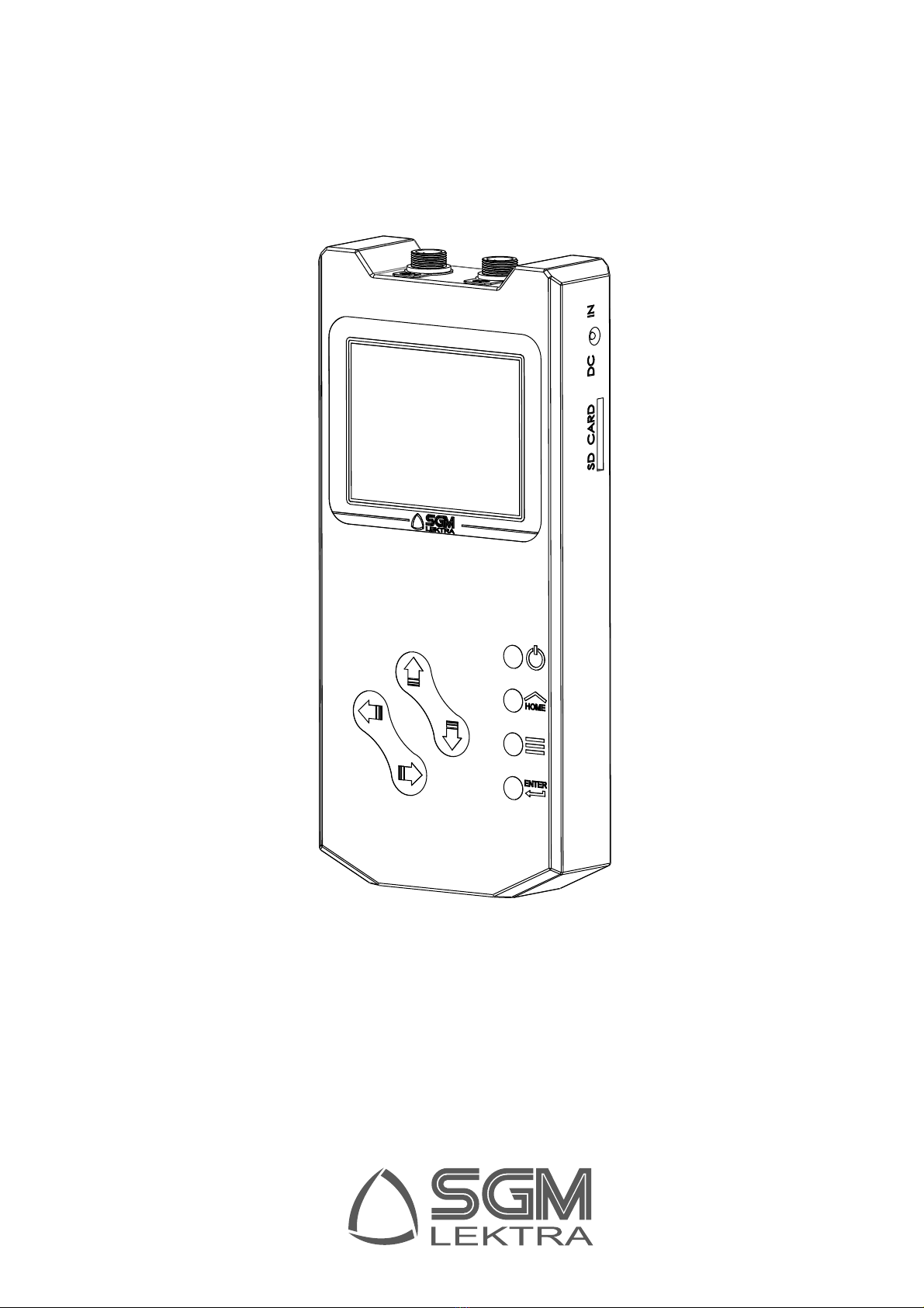
SGM-200H - product
2-PRODUCT
1. Transducer connectors
2. Charging connector
3. SD card
4. “ON” LED
5. “Charging” LED
6. ON/OFF key
7. Main screen key
2.1 IDENTIFICATION
Every instrument has an adhesive identification plate on which the main information about the product is outlined.
The following image describes the information and data on the plate.
1. Product code
2. Serial number
3. Power supply
SGM-200HTM1HD
FU0101600357
3
1Mod.
P. S .
S.N.
Batt. 4,8V 300mA/h
2
10
12
11
13
9
8
7
6
2
3
5
4
1
14
8. Cancel/annul key
9. Confirm key
10. UP
11. DOWN
12. LEFT
13. RIGHT
14. Display

Page 5 di 32
www.sgm-lektra.eu
SGM-200H - prodotto
Diameter
Pipe
ș
Upstream
transducer
Downstream
transducer
T2
T1
Pipe
thickness
D
VLQș
¨7
T1•T2
V=
Towards
direct flow
2.2 PRINCIPLE OF OPERATION
The SGM-200H measures the transit time through the two transducers which alternately transmit and receive a
sequence of sound pulses.
The difference in the measured transit time is directly related to the fluid speed in the pipe, as indicated in the
figure below.
When the speed of the fluid in the pipe and its geometry is known, the SGM-200H calculates the instantaneous
flow rate.
“Clamp on” transducers enable an easy installation; they are installed outside the pipe at a specific distance from
each other. They can be installed with V (2 sound tracts), W (4 sound tracts) or Z (1 sound tract) methods.
The choice of installation method depends on the pipe and on the characteristics of the fluid.
θ= angle of the sound path
D = diameter of the pipe
T1 = transit time of sound between upstream and downstream transducers
T2 = transit time of sound between downstream and upstream transducers
∆T = T2 - T1
2.3 GENERAL CHARACTERISTICS
2.3.1 Applications
The SGM-200H has several possible applications. The dimensions of the pipe can vary from 20 to 4000 mm
(0.79 to 157 inches) while liquids can be: ultra-pure, drinking water, chemicals, dirty water, cooling water,
river water, etc.
Since clamp-on transducers are applied externally to the pipe, they are not in contact with the liquid and have
no moving parts, the transmitter does not suffer damage due to wear, scale or pressure.
2.3.2 Data Integrity function
All the configuration values entered by the user are saved in the EE PROM, which is protected by a password
to prevent accidental changes. The transmitter is equipped with a clock for memorising the date and time of the
measurement, and runs on battery power. Should the batteries drain completely, it will be necessary to re-set the
date and time parameters.

Page 6 di 32 www.sgm-lektra.com
3-TECHNICAL SPECIFICATIONS
Display
3.5”, 320x240pixel, 65536 colours; auto switch offafter 10 minutes of inactivity
Data displayed
instantaneous flow rate; flow rate totalisers; instrument parameters
Languages
Italian, English, Chinese
Keyboard
8 keys
Case
ABS
Dimensions
218x103x35mm
Weight
400g
Temperature
-20 ÷ 60°C
Linearity
± 0.5%
Repeatability
± 0.2%
Total accuracy
± 1%
Max liquid speed
12 m/s
Pipe diameter
DN20 ÷ DN4000
Rechargeable Batteries
integrated, Ni-MH, 4x1,2V 300mA/h, 48h autonomy
Battery charger
100÷240Vac; 12Vdc out, 1.25A max current
Consumption
average 100mA, maximum 310mA, in stand by 100uA
Totaliser
7 digits for positive, negative and net
Data logger
On SD or SDHC card with capacities from 512Mb to 32Gb
16GB, they can store data for 10 years
Intervallo di memorizzazione data logger
5s, 10s, 20s, 30s, 60s
Clamp-on transducers
TS-2 type suitable for pipes from 20 to 100mm (-30÷90°C)
TM-1 type suitable for pipes from 50 to 700mm (-30÷90°C)
TL-1 type suitable for pipes from 300 to 4000mm (-30÷90°C)
Clamp-on transducers assembled on metric rail
HSNN type suitable for pipes from 20 to 100mm (-30÷90°C)
HMNN type suitable for pipes from 50 to 300mm (-30÷90°C)
HMEN type suitable for pipes from 50 to 700mm (-30÷90°C)
Clamp-on transducers for high temperatures
TS2H type suitable for pipes from 20 to 100mm (-30÷160°C)
TM1H type suitable for pipes from 50 to 700mm (-30÷160°C)
SGM-200H - technical specifications
Page 7 di 32
www.sgm-lektra.eu
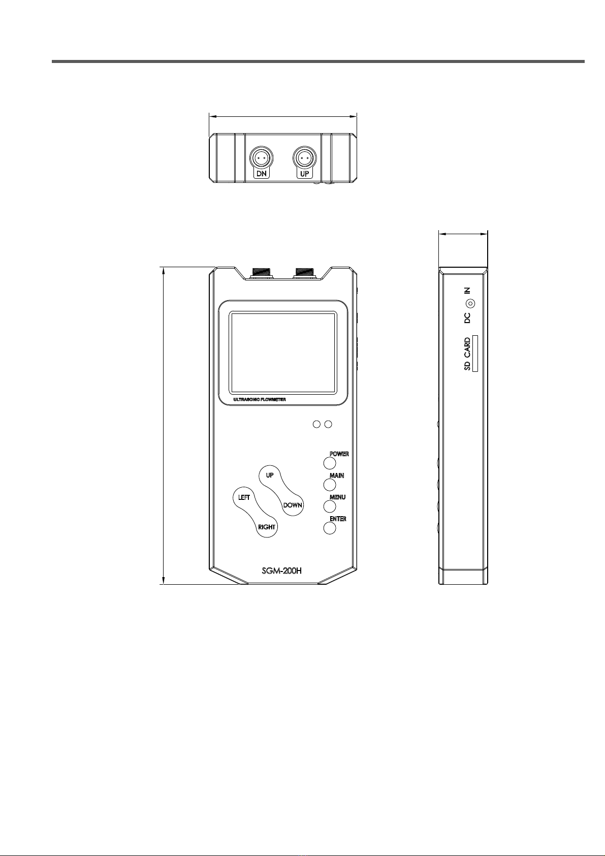
SGM-200H - dimensions
4-DIMENSIONS
220
34
102,5
4.1 MECHANICAL DIMENSIONS SGM-200H
Page 8 di 32 www.sgm-lektra.com
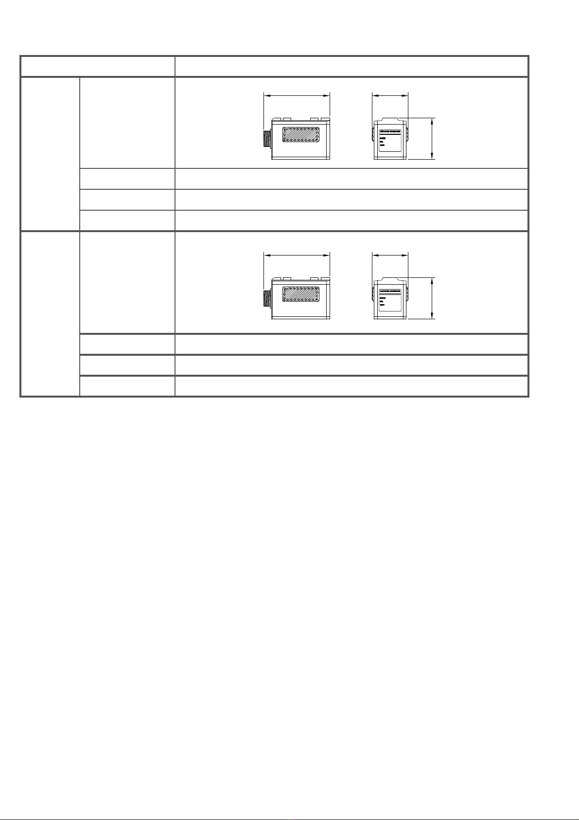
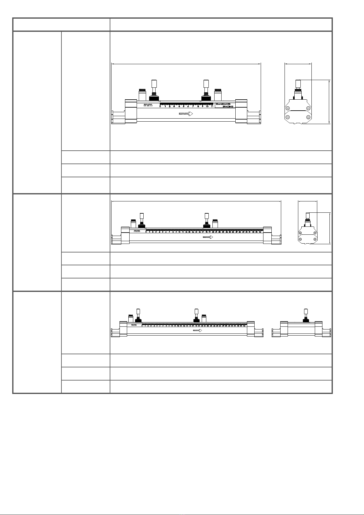
SGM-200H - dimensions
Transducer Model Features
TS-2
Dimensions
51 28
32
Pipe Ø range 20÷100mm (¾” ÷ 4”)
Temperature -30 ÷ +90°C
Parameter 13 >STANDARD S1
TS2H
Dimensions
51 28
32
Pipe Ø range 20÷100mm (¾” ÷ 4”)
Temperature -30 ÷ +160°C
Parameter 13 >STANDARD S1
4.2 DIMENSIONS AND CHARACTERISTICS OF THE TRANSDUCERS
Page 9 di 32
www.sgm-lektra.eu
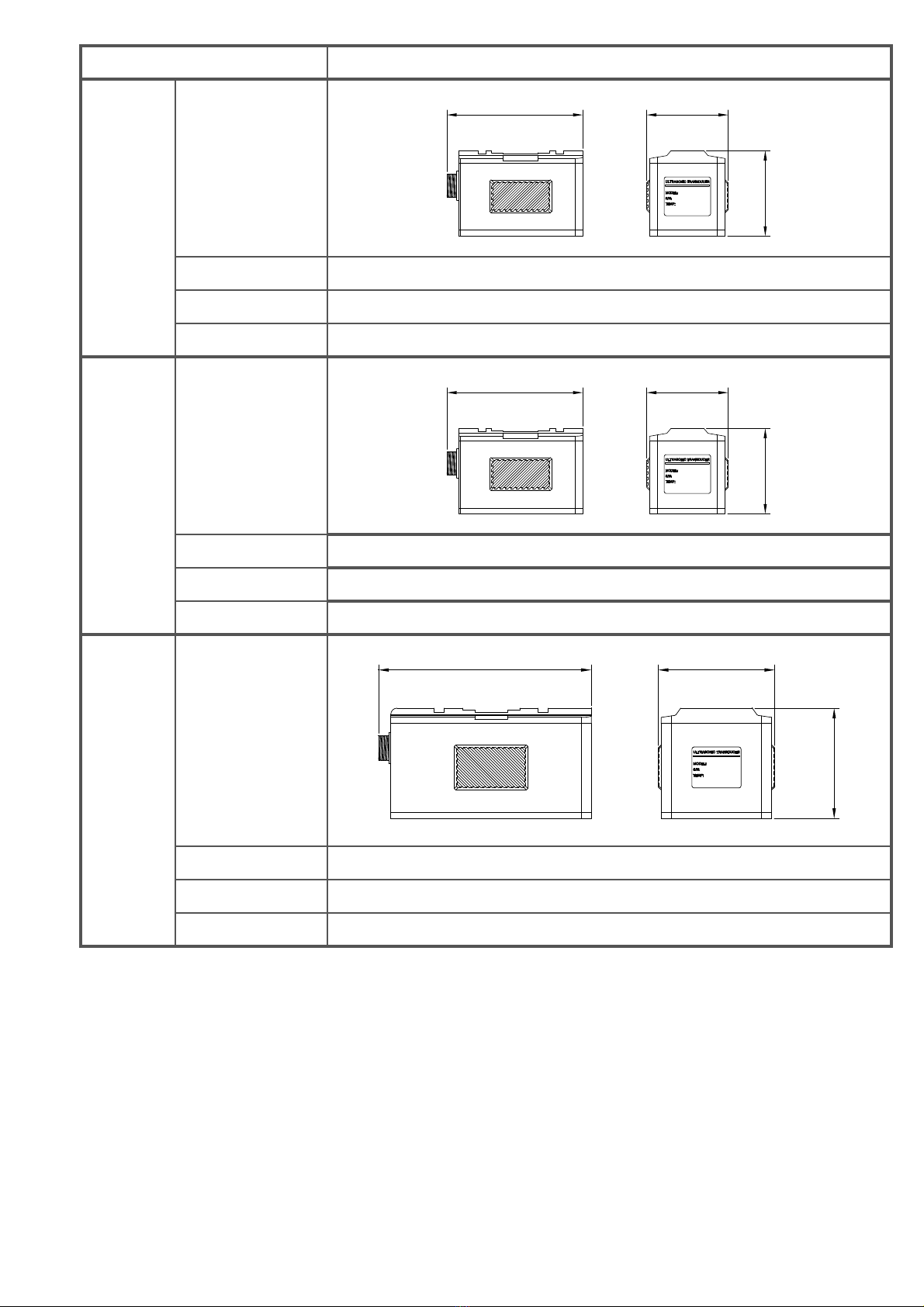
SGM-200H - dimensions
Transducer Model Features
TM-1
Dimensions
70 42
44
Pipe Ø range 50÷700mm (2” ÷ 28”)
Temperature -30 ÷ +90°C
Parameter 13 >STANDARD M1
TM-1H
Dimensions
70 42
44
Pipe Ø range 50÷700mm (2” ÷ 28”)
Temperature -30 ÷ +160°C
Parameter 13 >STANDARD M1
TL-1
Dimensions
104 57
54
Pipe Ø range 300÷4000mm (12” ÷ 160”)
Temperature -30 ÷ +90°C
Parameter 13 >STANDARD L1
Page 10 di 32 www.sgm-lektra.com
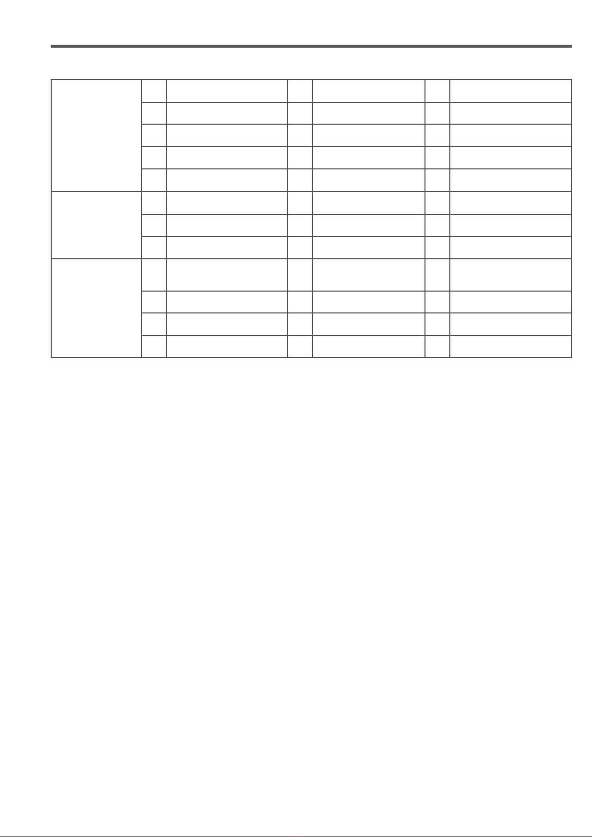
SGM-200H - dimensions
Transducer Model Features
HSNN
Dimensions
320 57
95
Pipe Ø range 20÷100mm
Temperature -40°C ÷ +90°C
Parameter 13 >STANDARD HS
HMNN
Dimensions
570 57
95
Pipe Ø range 50÷300mm
Temperature -40°C ÷ +90°C
Parameter 13 >STANDARD HM
HMEN
Dimensions
Pipe Ø range 50÷700mm
Temperature -40°C ÷ +90°C
Parameter 13 >STANDARD HM
Page 11 di 32
www.sgm-lektra.eu
SGM-200H - instrument parameters
5-INSTRUMENT PARAMETERS
5.1 PARAMETER TABLE
Basic
parameters
01 Pipe Circumference 02 Pipe Outside Diameter 03 Pipe Thickness
04 Pipe Inner Diameter 05 Pipe Material 06 Pipe Mat. Sound Speed
07 Internal Coat. Mat. 08 Coat. Sound Speed 09 Coating Thickness
10 Type of Liquid 11 Sound Speed In Liquid 12 Liquid Viscosity
13 Type of Transducer 14 Assembly of Transducer 15 Transd. Assemb. Distance
Flow Rate
16 Unit of Measure Sel. unit 17 Instan MisQ Unit 18 Totalis, Unit
19 Multi Total Fact. 20 Tot Net Totalis. 21 Positive Totalis.
22 Negative Totalis. 23 Totalis. Resetting 24 Port Low Cutoff
System
parameters
25 Zero Setting 26 Zero Setting 27 Zero Manual Sett.
28 Signal Muffling 29 Scale Factor 30 Products no.
31 Language 32 Interval Record 33 Date & Time Set
34 Curve Range Set 35 Not used 36 Not used
5.2 BASIC PARAMETERS
01 Outer circumference of the pipe.
02 Outside diameter of the pipe; from 0 to 18000mm.
03 Wall thickness of the pipe.
04 Inner diameter of the pipe.
05 Pipe material.
For non-standard materials, select “Other” and enter the sound speed in menu 06.
06 Sound speed in the pipe material; only for non-standard materials.
07 Inner liner material, select “None” for pipes without coating; for non-standard materials, select the “Other” and
enter the sound speed in menu 08.
08 Speed of sound in the coating; only for non-standard materials. 09 Thickness of the internal coating,
where provided.
10 Type of fluid; For non-standard fluids, select “Other” and enter the sound speed in menu 11.
11 Sound speed in the fluid; only for non-standard fluids.
12 Viscosity of the fluid; only for non-standard materials.
13 Transducer model.
14 Method for transducers installation.
15 Distance for installation transducer (automatically calculated by the meter).
Page 12 di 32 www.sgm-lektra.com
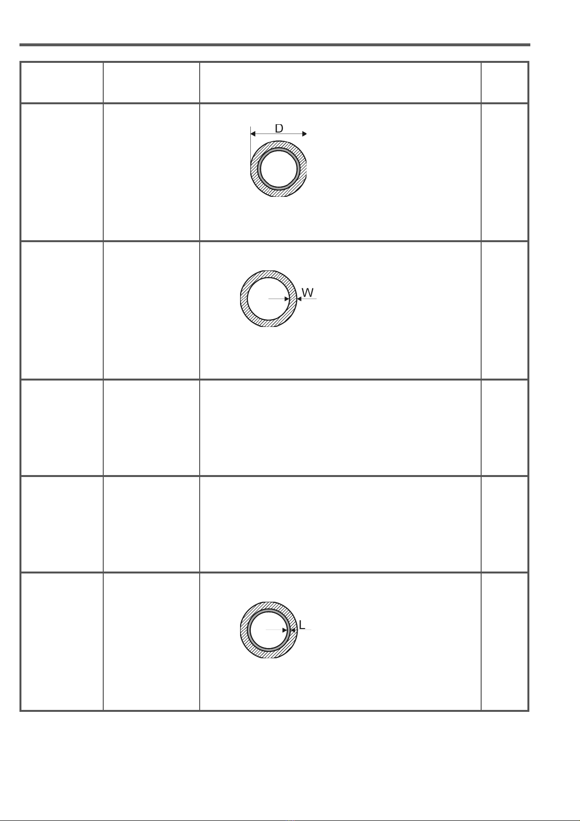
SGM-200H - description of main parameters
Name Display view Description Param.
Ø pipe
OUTSIDE
DIAMETER OF
PIPE
(Cross section of the pipe)
Outside diameter of
the pipe 02
Pipe thickness THICKNESS OF
THE PIPE
(Cross section of the pipe)
Thickness of the pipe 03
Pipe material MATERIAL OF THE
PIPE
CARBON STEEL; STAINLESS STEEL; CAST IRON; SWEET
IRON; COPPER; PVC-POLYVINYL CHLORIDE; ALUMINIUM;
FIBER CEMENT-AMI; VETROEPOXY FIBER; OTHER
MATERIALS
05
Inner coating
material
MATER. INTERNAL
COATING
NO INTERNAL COAT.; TAR. EPOXY; RUBBER; CONCRETE;
POLYPROPYLENE; POLYSTYRENE; POLYESTER;
PE-POLYETHYLENE; EBONITE-HARD RUBBER; TEFLON;
OTHER MATERIALS
07
Thickness of the
inner pipe coating
COATING
THICKNESS
(Cross section of the pipe)
Pipe inner coating
thickness 09
6-DESCRIPTION OF MAIN PARAMETERS
Page 13 di 32
www.sgm-lektra.eu
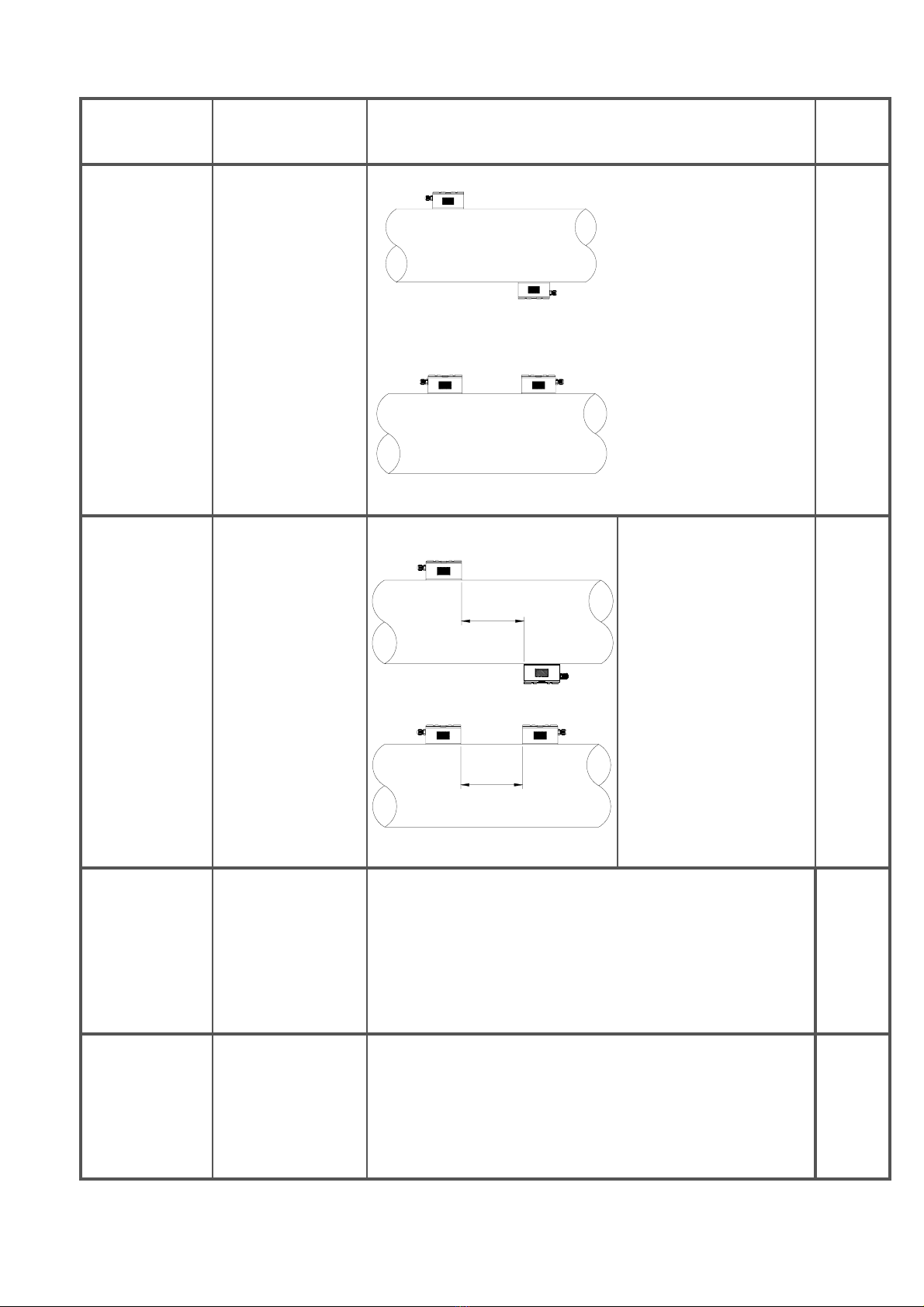
SGM-200H - description of main parameters
Name Display view Description Param.
Transducer
method of
assembly
INSTALLATION OF
TRANSDUCERS
Z mode The transducers can be
positioned on the pipe in 3
different modes: V; Z; N; W
and V.
The choice of installation
method depends on the
application conditions.
Methods of assembly
the most used are Vand Z.
14
V and W
mounting method
Transducer
installation
distance
TRANSDUCER
INSTALLATION
DISTANCE
Lout
Lout
The axial assembly
distance, Lout, is
automatically determined
based on the following data
previously
included: Ø pipe; pipe
thickness; pipe material;
internal coating, if any, with
thickness; transducer
installation method.
15
Instant flow rate
unit
Q INSTANT. UNIT
OF MEAS.
Unit of measurement associated with instantaneous flow
measurement.
It is possible to select 8 different units of measurement for the
volume: CUBIC METERS (m3); LITRES (l); US GALLONS(Gal);
UK GALLONS (IGL); MILLION US GALLONS; CUBIC FEET
(CF); OIL BARRELS (OB); UK OIL BARRELS (IB)
and 4 different units of measurement for time:
/SEC.; MIN.; /HRS; /DAY
17
Flow totalisers
unit of
measurement
TOTALISATI
ON UNIT
Unit of measurement associated with flow totalisers. It is
possible to select 8 different units of measurement: CUBIC
METERS (m3); LITRES (l); US GALLONS (Gal);
UK GALLONS (IGL); MILLION US GALLONS; CUBIC FEET
(CF); OIL BARRELS (OB); UK OIL BARRELS (IB)
18
Page 14 di 32 www.sgm-lektra.com
SGM-200H - description of main parameters
Name Display view Description Param.
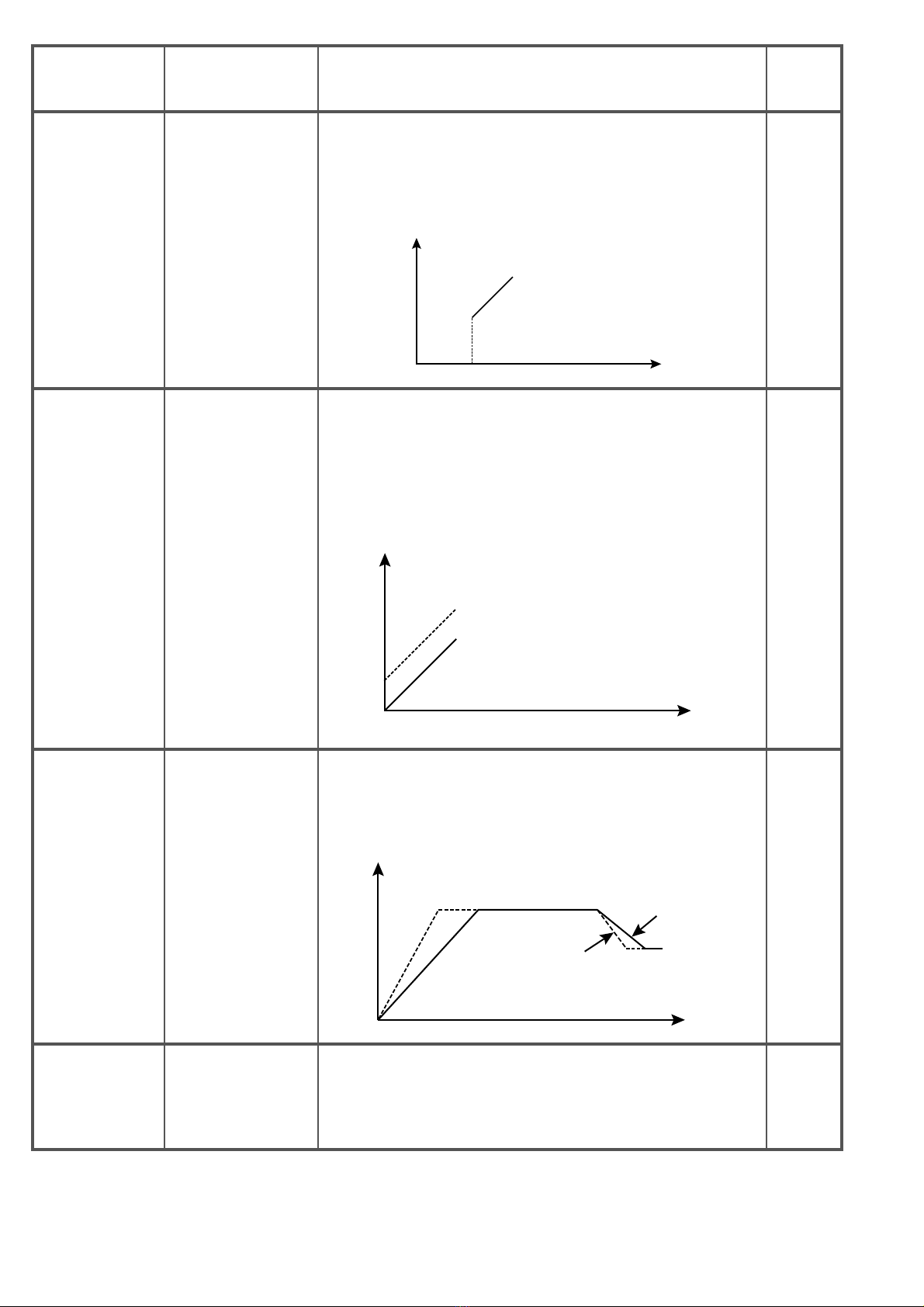
Flow rate cutoff
value Port Low Cutoff
When the measured flow rate is lower than the cutoffvalue, the
displaywillshowtheinstantaneousflow rate measurement as a fixed0.
Range 0.000 ÷ 0.25m/s
Disp
l
aye
d
owrate
Actual
owrat
e
LV
24
Zero flow
calibration Zero Settings
When the fluid in the pipe is stationary, the flow rate value must
be 0. If it is not the case, it is necessary
to calibrate the Zero flow.
N.B. - Make sure that the fluid is perfectly still and that the pipe
is full
Displayed
owrate
Before setting
After setting
Actual
owrate
25
Integration
coefficient Signal damping
The integration coefficient defines the upward or downward
updating speed of the displayed flow measurement with respect
to the variation of the detected flow measurement.
Range: 0÷999 seconds
Flowrate
Actual
owrate
Displayed
owrate
Time
28
Correction
coefficient Scale Factor Coefficient for correction of measurement accuracy.
Range 0.5 ÷ 1.5% 29
Page 15 di 32
www.sgm-lektra.eu
SGM-200H - installation
7-INSTALLATION
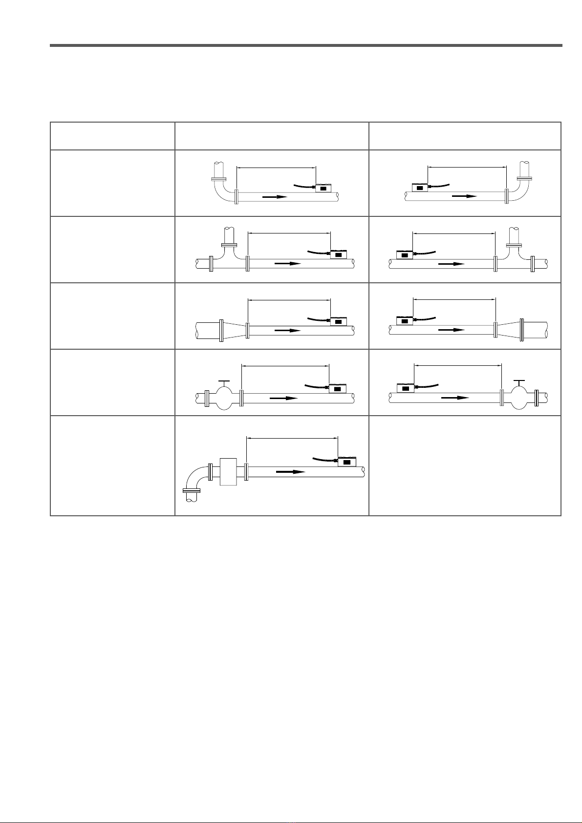
7.1 SELECTION OF MEASUREMENT POINT
The transducers must be installed on a section of pipe that allows to respect the minimum distance between the
element of resistance to flow, such as curves or extensions, and the measurement point.
See table below.
Flow resistance element Upstream side Downstream side
90° bend
15 x DN 5 x DN
T link
40 x DN 5 x DN
Adapters
18 x DN 5 x DN
Valves
40 x DN 5 x DN
Pumps
20 x DN
P
7.2 SETTING OF THE PARAMETERS IN THE INSTRUMENT
From the main page, press MENU to access the instrument menu; at the top right the letter "S" will appear on a blue
background.
Press ENTER to access the first page of the menu: PARAMETERS SET
With UP and DOWN it is possible to select the parameter within the page, with LEFT and RIGHT it is possible to move
to the previous/next page.
Once the parameter has been selected, by pressing ENTER the setting is accessed:
for multiple choice parameters, with the UP and DOWN keys it is possible to scroll through the available options and
choosing one with ENTER; for numeric fields, with UP and DOWN it is possible to increase/decrease the numeric
value of the selected digit, with LEFT and RIGHT it is possible to move to the adjacent digit.
Confirmation of the set value occurs by pressing ENTER. To exit the menu simply press MAIN.
Page 16 di 32 www.sgm-lektra.com
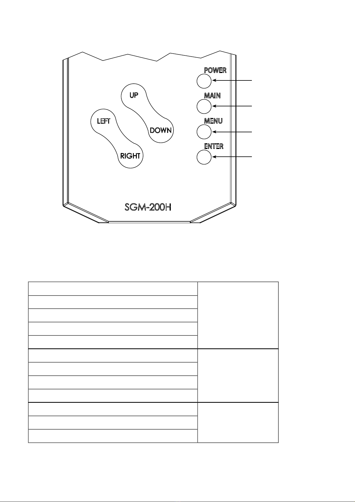
SGM-200H - installation
“UP” and “DOWN”: scroll
Parameter selection
“LEFT” or “RIGHT”: menu page change
“ENTER”: confirms the selection
“MENU”: cancels the modification of the parameter
“MAIN”: returns to the main screen
“ENTER”: confirms the selection and the number turns red
Numeric settings
“UP” or “DOWN”: increases or decreases the value of the digit
“LEFT” or “RIGHT”: selects the digit
“ENTER”: saves the parameter
“ENTER”: confirms the selection and the writing turns red
Option settings
"UP" or "DOWN": selects the parameter option
“ENTER”: saves the parameter
ON/OFF key
Main screen key
Cancel/annul key
Confirm key
UP KEY: Scroll up / Value increment. Flow rate curve display (in run mode).
DOWN KEY: Scroll down / Value decrease. Datalogger status display.
LEFT KEY: (LEFT + ENTER) data storage start (LEFT + MENU) data storage end.
Datalogger quick guide Menu selection / Menu page selection.
RIGHT KEY: SD memory status. Menu selection / Menu page selection.
7.3 KEYBOARD

Page 17 di 32
www.sgm-lektra.eu
SGM-200H - installation
7.4 SET THE LANGUAGE OF THE MENUS
Set the language in parameter 31.
7.5 SET DATE AND TIME
Set the date and time in parameter 33.
7.6 SET THE MEASURING SYSTEM
Set metric (mm) or British (in) system in parameter 16.
7.7 SET THE UNIT OF MEASUREMENT OF THE MEASUREMENT FLOW
Set the unit of measurement of the instantaneous flow rate to parameter 17.
7.8 SET THE UNIT OF MEASUREMENT OF THE TOTALISER
Set the unit of measurement of the totaliser in parameter 18.
7.10 ESSENTIAL SETTINGS FOR THE INSTALLATION OF THE TRANSDUCERS
• Set the value of the EXTERNAL diameter of the pipe in parameter 02; alternatively, the value of the pipe
circumference can be entered in parameter 01
• Set the pipe thickness value in parameter 03.
• Set the pipe material in parameter 05; if the material is not present in the options, select “Other” and set the
sound speed in the pipe material in parameter 06.
• Set the possible INTERNAL coating material of the pipe: if not present, choose NONE; if present but not foreseen
in the options, set the sound speed in the internal coating material in parameter 08.
• Set the thickness of the coating material, if present, in parameter 09.
• Set the type of fluid in parameter 10; if not present in the options, select “Other” and enter the sound speed in the
fluid in parameter 11 and the viscosity of the fluid in parameter 12.
• Set the transducer model in parameter 13.
• Set the assembling method of the transducers in parameter 14.
At this point, the instrument automatically provides the installation distance of the transducers in parameter 15.
7.9 SET THE "SCALE FACTOR" VALUE
The “scale factor” value to be set is shown on the calibration certificate of each pair of transducers supplied.
For setting, use parameter 29.

Page 18 di 32 www.sgm-lektra.com
SGM-200H - installation
7.11 POSITIONING TYPE SELECTION
The selection of the type of positioning of the two transducers, Z-Mode, or V-Mode or W-Mode,
depends on the pipe DN involved in the measurement:
DN20÷50 - recommended installation W-Mode
DN50÷250 - recommended installation
V-Mode DN250÷4000 - recommended installation Z-Mode
7.12 PLACING THE POSITIONING
After entering the parameters relating to the pipe and the type of positioning of the transducers, the conversion unit
automatically calculates the axial mounting distance between the two transducers in parameter 15, TRANSD. ASSEMB.
DIST. The value of 15 is used to trace the exact position of the transducers on the pipe.
7.13 TRACKING TOOLS
To track the transducer positioning points on the pipe surface, simple tools are sufficient:
- a paper tape with a width of at least 50mm..
- a pencil or a fine-tipped marker
- a meter
7.14 TRACKING METHODS
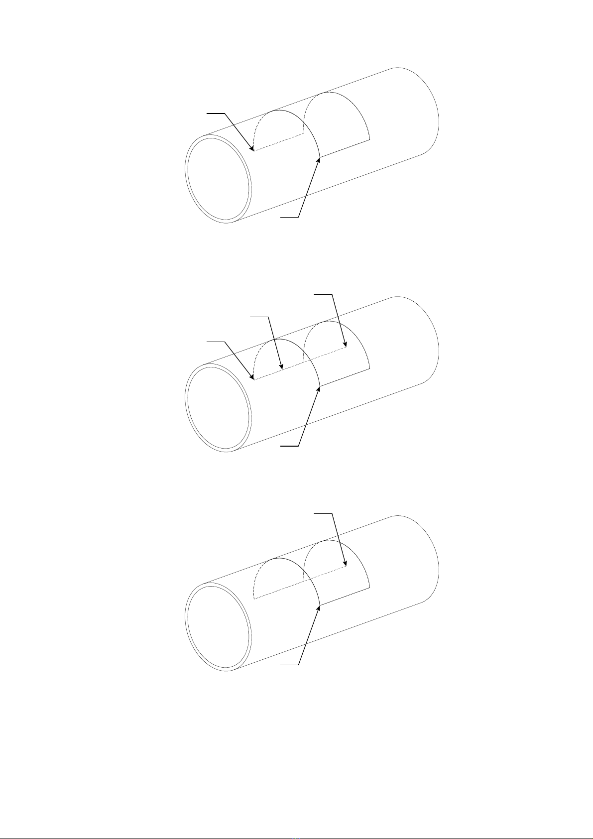
7.14.1 Z-type positioning
To correctly position the transducers, proceed as follows:
1) Wrap the pipe with the paper tape, ensuring that the edges of the tape are perfectly overlapping each other.
Trace the circumference “C” on the pipe with the pencil or the fine-tipped marker and, at the same time,
trace the measurement point of the circumference on the paper tape.
C
2) Remove the paper tape and fold the part corresponding to the circumference in half. Place the paper tape
back on the pipe.
The intersection point, called "A", is the assembling position of one of the two transducers.
A
Page 19 di 32
www.sgm-lektra.eu
SGM-200H - installation
4) On the pipe, trace the straight line "D" from point "B" of length equal to the distance previously calculated and
displayed by the conversion unit in parameter 15 to obtain point "E".
D
A
B
E
5) Now the positions of both transducers have been obtained, points marked with the letter “A” and “E”.
A
E
3) Locate point “B” positioned 180° from point “A” using the ribbon folded in half.
A
B

Page 20 di 32 www.sgm-lektra.com
SGM-200H - installation
7.14.2 V or W type positioning
To correctly position the transducers, proceed as follows:
1) Determine a point called “A”, which will be the assembling position of one of the two transducers.
A
2) On the pipe, trace the straight line "S" parallel to the pipe from point "A" of length equal to the distance previously
calculated and displayed by the conversion unit in parameter 15 to obtain point "B".
A
B
Table of contents
Other SGM LEKTRA Measuring Instrument manuals


