SGM LEKTRA SGM-100F User manual
825B109E
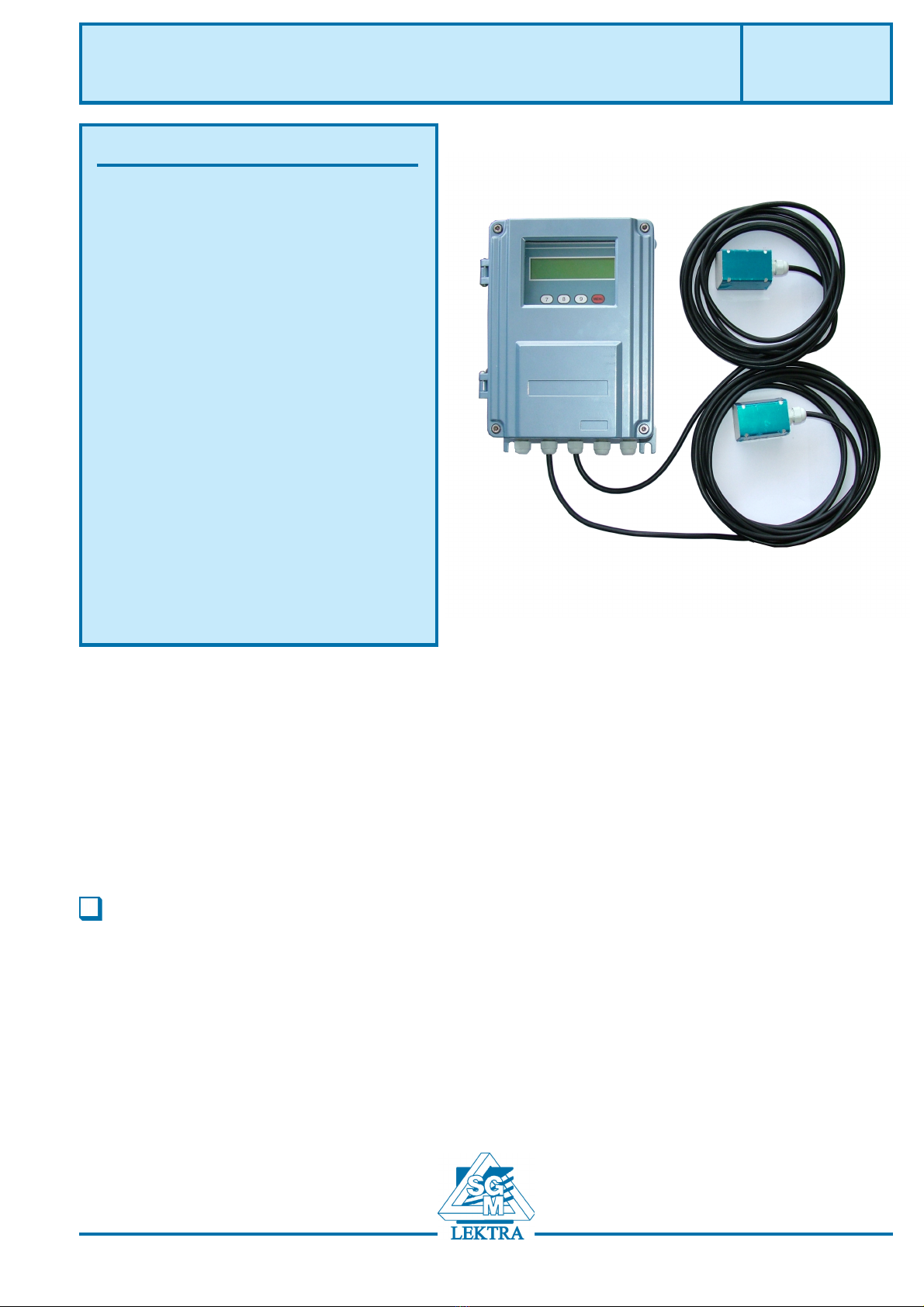
SGM-100F
Transit time ultrasonic flowmeter
applied solutions for the application
The SGM-100F is composed by a digital converter and two clamp-on or insertion type ultrasonic transducers.
It is designed to measure the fluid velocity of a liquid inside a closed conduit. The transducers are a non-
contacting, clamp-on type, which provide benefits of non-fouling operation and easy installation.
The DSP digital technology (Digital Signal Processing) ensure a low sensibility of the instrument against
potential transient factors.
General
Features
Piping : 20mm-4000mm
Protection class transmitter: IP65
Protection class transducer: IP68
Display: 2x20 digit alphanumeric
backlighted
Keypad: 4x4
Displayed data: istantaneous flowrate, flow totalizer
Housing: Aluminium
Mounting: wall
Output:: Sel. 4÷20m A or 0÷20mA
Total accuracy: ± 1%
Repeatibility: ±0,2÷0,5%
Linearity: ±0,5%
Basic measurement period: 500ms
Serial port: RS 232 (optional RS 485)
Programmable frequency output: 12÷9999HZ
Relay output: for pulse totalizer or alarm
Medium speed: ±32m/s
Working temperature: -30÷80°C
Instrument humidity: non condensing 85% RH (40°C)
Sensor process temperature: 0÷150°C
Sensor humidity: non condensing 98% RH (40°C)
Power supply: 230Vac / 24Vdc
Dimensions: 251x192x80mm
Weight: 3,1Kg

Page 2 of 24
SGM-100F - Working principle
0. Working principle
Where:
0= include angle for the flow direction
M = transit time of the ultrasonic signal
D= Internal pipe diameter
Tp= Transit time in the forward direction
Tdown= Transit time in the reverse direction
∆T= Tup-Tdown
Fig.1
downup
TT
TMD
V
•
∆
×=
θ
2sin
The SGM-100F utilizes two transducers which work as ultrasonic transmitters and receivers.
They are clamped on the outside of a closed pipe at a specific distance from each other. They can be mounted in V
position (the sound crosses the pipe twice), in W position (the sound crosses the pipe 4 times) or in Z position
(mounted on opposite sides of the pipe - the sound crosses the pipe once). The selection of the mounting position
depends on pipe and on liquid characteristics.
The SGM-100F operates by alternately transmitting and receiving a frequency modulated burst of sound energy
between the two transducers and measuring the transit time that takes the sound to travel between them. The
difference in measured transit time is directly and exactly related to the velocity of the liquid inside the pipe (fig.1).
Down stream transducer
spacing
fl
o
Upstream transdu
c
Tdow
n
Tup θ
Fig. 1

Page 3 of 24
SGM-100F - Features
1 Features
1.1 Mechanical dimensions
1.2 Applications
1. water, sewage with low particle content and seawater
2. water supply and drainage water
3. power plants, nuclear power plant, thermal and hydropower plants, heat energy, boiler feed water and
energy management system
4. metallurgy and mining application
5. petroleum and chemicals
6. food, beverage and pharmaceutical
7. pulp and paper
8. pipeline leak detection
9. network monitoring system, energy and flow computer management
Page 4 of 24
SGM-100F - Features/Operation
1.3 Product Identification
Every instrument has an 8 digit identification number (ESN) which provides the information of version and
manufacring date. It is displayed on menu M61 and can be employed for instrumentation management.
1.4 Specifications
metIsnoitacificepS
tinUniaM
elpicnirP eslupitlum,egatlovwoL
ycaruccA sm005:doirepgnirusaem%5.0foytilibataeper,rettebro%1
cteemit,etarwolf,wolfdetalumuccadnawolfsuoenatnatsniswohsyalpsidDCLdethgtilkcaB
tuptuO
OK1-0foecnadepmi,Am02-0roaM02-4fotuptuotnerruccirtcelE
%1.0fonoisicerp
wolfgnitargetnirowolften/evitagen/evitisop:tuptuo)TCO(rotcelloCnepO
langisycneuqerfetarwolfecnatsnirolangiseslupetar
srecudsnarT
noitcennoc
elbac
m002:htgnelxam-tm5x2 gninraW :rewophgihmorfrafdecalpebtsumelbacnoitcennoc
snoitcennocelbacgnihctiwsdna
gnipiP
leetsssalg,munimula,CVP,reppoc,epiptnerruc,noritsac,leetssselniats,leetS
mm0004-mm02
pmupehtmorfyawaD03,D5maertsnwod,D01maertspU:snoitseggusnoitallatsnI
sdiulF noitagaporpevawcinosartlufoelbapacsdiuqilrehtodnaslio,egawes,retawaes,retaW
gnitarepO
noitidnoc
erutarepmeTC°051+~0srecudsnarTC°08~03-rettimsnarT
ytidimU nahtrewolhtpedforetawrednukrownac:recudsnarTHR%58:tinuniaM
m3
ylppusrewoP V42CD/V032CA,w2
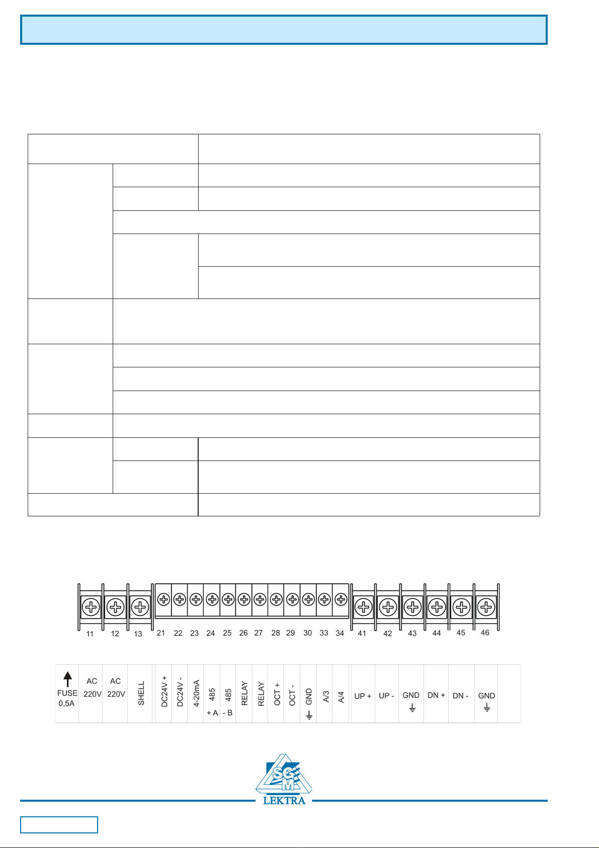
2.1 Connections

Page 5 of 24
SGM-100F- Operation
2.2 Power on
Standard power supply of SGM-100F is 230VAC. Please check power supply voltage before connecting the unit.
Once the instrument is switched on, it will run a self diagnostic program. If there’s any anomaly the corresponding
error message will be displayed. Generally, there should be no display of error messages, and the flow meter will go
to the most commonly used Menu Window Number 01 (short for M01) to display the Velocity, Flow Rate, Positive
Totalizer, Signal Strength and Signal Quality, based on the pipe parameters configured last time by the user or by the
initial program.
The operation on the keypad does not interfer with the measurement because there’s the simultaneous processing
technology.
When power is on, the user can see on menu window M01 that it is adjusting the gain of the amplifier. Progress S1,
S2, S3 and S4 will be displayed on the left upper corner of the display and after the adjustment the flowmeter will go
into the normal measurement mode, with “R” displayed on the left upper corner.
If the instrument is running for the first time or it has been installed in a new position, the user needs to enter new
pipe parameters. Any parameter will be recorded permanently into the NVRAM of the SGM-100F, until new
modification.
2.3 Keypad
The SGM-100F keypad has 16 keys.
Keys from to and are to enter numbers or menu numbers
Key is for entering the previous menu window. It can be also used to increase a numeric value.
Key is for entering the next menu window. It can be also used to decrease a numeric value.
Key is for moving left or to delete the left character.
Key is for selecting a menu option or for confirm a modification.
Key is for the direct menu window jump over
2.4 Menu windows
The interface has about 100 different menu windows, numbered from M00 to M99.
There are two methods to enter menu windows:
(1)Direct entering by pressing followed by two digit-number keys. For example, to enter M11 menu (pipe
external diameter) press in sequence .
(2)Research by and , scrolling the windows numbers. By pressing the user will display the previous
menu window and by pressing will display the next one.
There are three different types of menu windows:
(1) for number/value entering, like pipe diameter dimensions
(2) for options selection, like pipe material
(3) for values display, like velocity, flow rate ecc.
For number entering windows press directly the digit-numbers and to confirm. For example, if the outer diameter
of the pipe is 219.2345, select the menu window M11 and press in sequence:
For selecting and modifying the parameters, press and select the option by pressing and . Press then
to confirm.
For example, if the pipe material is SS316, select menu window M14, press and select the pipe material by
pressing or or by digiting the number showed before the material (in this case 1).
Press then to confirm the choice.

Page 6 of 24
2.4 Menu windows types
M00÷M09 for values display (flowrate, velocity, date and time, totalizer, battery volatge and estiomated working
time)
M10÷M29 for entering pipe parameters
M30~M38 for selecting flow rate unit and totalizer unit
M40÷M49 for response time, zero and calibration setup and password modification
M50÷M53 for data logger setup
M60÷M78 for time-keeper setup, ESN information and alarms
M82 for totalizer data display
M90÷M94 for diagnostic
M97÷M99 command windows (contact SGM LEKTRA)
M+0÷M+8 additional fucntions, as calculator, and for displaying total working hours, turn-on and turn-off times
and date and time of the single operations.
2.5 Parameters setting
In order to achieve a proper measurement, proceed with the configuration of the following parameters:
(1) Pipe outer diameter
(2) Pipe wall thickness
(3) Pipe material. In case of non standard materials (not listed) it’s necessary to enter also the relevant medium
sound speed.
(4) Liner material, if present, and the relevant medium sound speed and thickness
(5) Liquid type. In case on non standard liquid (not listed) it’s necessary to enter also the relevant medium sound
speed.
(6) Transducers type
(7) Transducers mounting method
(8) Transducers mounting distance (showed on menu window M25)
For standard pipe materials and standard liquids refer to the following instructions:
(1) Press to input the pipe outer diameter and press to confirm.
(2) Press to enter menu M12 and input the pipe wall thickness. Press to confirm.
(3) Press to enter menu M14 and press to enter selection mode. Use or to select the material
and press to confirm.
(4) Press to enter menu M16 and press to enter selection mode. Use or to select the lining
material and press to confirm.
(5) Press to enter menu M20 and press to enter selection mode.Use or to select the liquid
and press to confirm.
(6) Press to enter menu M23 and press to enter selection mode. Use or to select the
transducers and press to confirm.
(7) Press to enter menu M24 and press to enter selection mode. Use or to select transducers
mounting method and press to confirm
(8) Press to enter menu M24 to install the transducers on the pipe and then press to go to menu M01
to check the parameters.
SGM-100F- Operation
Page 7 of 24
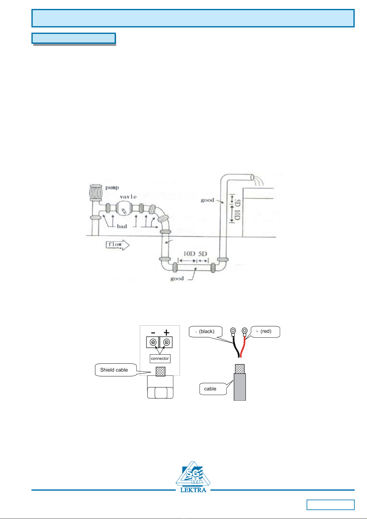
3.1 Measuring location
The first step of the installation process is the selection of an optimum place in order to obtain a more accurate
measurement. For this reason it is important to have a basic knowledge of the piping and of its plumbimg system.
An optimum place would be defined as a straight pipe length full of liquid, horizontally or vertically positioned.
Selection principles for an optimum installation:
(1) Install the transducers on the longer length of the pipe and make sure that the pipe is completely full of liquid.
(2) Make sure that the temperature on the location does not exceed the temperature range of the transducers. In
general the closer to the room temperature the better.
(3) Take the pipe fouling into consideration. Select a straight length of a relatively newer pipe. If the condition is not
satisfying, consider the fouling thickness as part of the liner for a better result.
(4) Remember that gas fase in the liquids is in the upper part of the pipe. Consequently on horizontal pipe
installations avoid to put the trasducers in the upper part.
3.2. Transducers installation
The SGM-100F transducers are made of piezoelectric crystals, both for transmitting and receiving the ultrasonic
signals through the wall of the liquid piping system. The measurement is realized by measuring the traveling time
difference of the ultrasonic signals. Since the difference is very small, the spacing and the alignment of the
transducers are important factors for the accuracy of the measurement and the performance of the measuring
system.
3 Installation
SGM-100F - Installation
Page 8 of 24
How to proceed with the installation:
(1) Locate an optimum position on the pipe, which has to be in good condition (no rust)
(2) Clean and dust the pipe surface.
(3) Apply adeguate coupler on the spot where the transducers have to be installed and leave no gap between the
pipe surface and the transducers.
To avoid gas bubbles (gas fase) inside the upper part of the pipe, the transducers should be installed horizontally
by the side of the pipe.
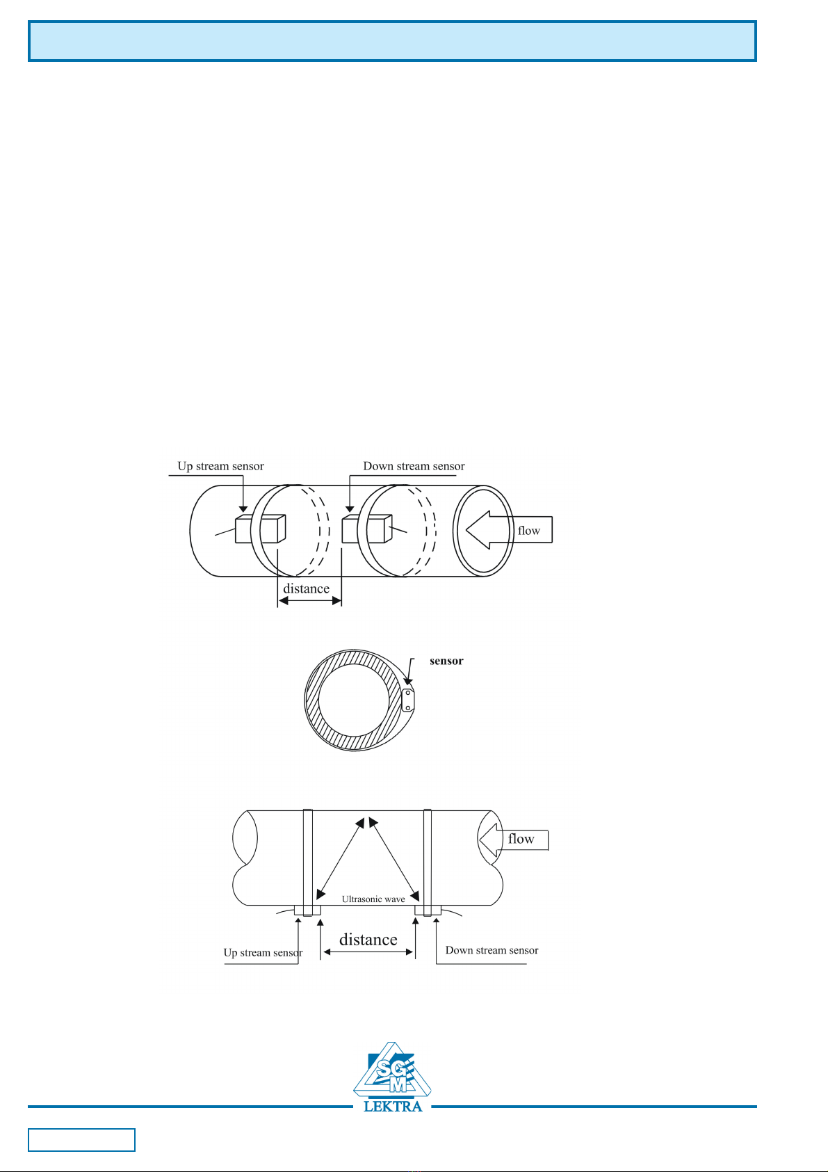
3.2.1 Transducers spacing
The spacing value shown in menu M25 refers to inner distance between the two transducers. The actual trasducers
spacing should be as close as possible to the spacing value. (see figures on next page).
3.2.2 V method installation
It is the most common used method for pipe with diameters ranging from 20 to 300 millimeters.
SGM-100F - Installation

Page 9 of 24
3.2.3 Z method installation
It is commonly used when the pipe diameter is between 300 and 500 millimeters.
SGM-100F - Installation
3.2.4 W method installation
It is usually used on little pipes with a diameter from 10 to 100 millimiters.

Page 10 of 24
SGM-100F - Installation
3.2.6 Insert sensor installation
Steps for a correct installation:
1- If the pipe is placed inside the wall, check that there’s sufficient space for the mounting of the insertion
sensor (min. distance between the wall and the pipe = 540mm)
2- Procure a drilling tool
3- Enter pipe parameter (in menu M23 choose option 5. “insertion B sensor” - in menu M24
choose 1. “Z method” - in menu M25 input installation distance)
4- Choose the right position and calculate the distance
5- Install the ball valve

Page 11 of 24
SGM-100F - Installation
6- Drill the pipe
1 sensor 2 bottom of ball valve 3 ball valve 4 screw
5 tight screw 6 connection 7 cable
7- Insert the sensor
1 sensor 2 bottom of ball valve 3 ball valve 4 screw
5 tight screw 6 connection 7 cable
L= A - b
A = sensor length b = pipe thickness L= external sensor length
8- Proceed with the electrical connection

Page 12 of 24
SGM-100F - Installation
3.3 Installation check-up
Through the checkup of the installation, one can: check the receiving signal strength, the signal quality Q value, the
traveling time difference of the signals, the estimated liquid speed, the measured traveling time of the signals and
the calculated traveling time ratio.
3.3.1 Signal strength
Signal strength indicates the amplitude of receiving ultrasonic signals by a 3-digit number. [000] means there is no
signal detected, and [999] refers to the maximum signal strength that can be received.
Although the instrument works well if the signal strength ranges from 500 to 999, stronger signal strength should be
pursued, because a stronger signal means a better result. The following methods are recommended to obtain
stronger signals:
(1) Relocate a more favorable location, if the current location is not good enough for a stable and reliable flow
reading, or if the signal strength is lower than 700.
(2) Try to polish the outer surface of the pipe, and apply more coupler to increase the signal strength.
(3) Adjust the transducers both vertically and horizontally while checking the varying signal strength, stop at
the highest position, and then check the transducers spacing to make sure the transducers spacing is the
same as shown in menu M25 .
3.3.2 Signal quality (Q)
Signal quality is indicated as the Q value on the instrument. A higher Q value would mean a higher Signal and Noise
Ratio (short for SNR), and accordingly a higher degree of accuracy would be achieved. Under normal pipe condition,
the Q value is in the range of 60-90, the higher the better.
Causes for a lower Q value could be:
(1) Interference of other instruments and devices such as a powerful transverter working nearby. Try to
relocate the flow meter to a new place where the interference can be reduced.
(2) Bad sonic coupling for the transducers with the pipe. Try to apply more coupler or clean the surface etc
(3) Pipes are difficult to be measured. Relocation is recommended.
3.3.3 Total transit time and Delta Time
The numbers displayed on menu window M93 are called total transit time and delta time respectively. They are the
primitive data for the instrument to calculate the flow rate inside the pipe. So the flow rate indication will vary
accordingly with the total time and delta time.
The total transit time should remain stable or vary little.
If the delta time fluctuates higher than 20%, it means there are certain kinds of problems with the transducer
installation.
3.3.4 Time ratio
between the Measured Total Transit Time and the Calculated Time
This ratio would be used to check the transducer installation. If the pipe parameters are entered correctly and the
transducers are installed properly, the value for this ratio should be in the range of 100±3. If this range is exceeded,
the user should check:
(1) If the pipe parameters are correctly entered.
(2) If the actual spacing of the transducers is right and the same as what the window M25 shows.
(3) If the transducers are installed properly in the right directions.
(4) If the mounting location is good and if the pipe has changed shape.
(5) If there is too much fouling inside the pipe.

Page 13 of 24
SGM-100F - Use
4 Use
4.1 How to check if the instrument works properly
When ‘R’ is displayed in the lowest right corner of LCD display, the instrument is working properly.
If an ‘H’ flashes on that place, there could be poor signal received. Please refer to the chapters on diagnosis.
If an ‘I’ is displayed, it means that there is no signal detected.
If a ‘J’ is displayed, it means that the hardware of this instrument could be out of order. Refer to the chapter on
diagnosis.
4.2 How to check the liquid flow direction
Make sure that the instrument works properly
Check the flow rate for the indication. If the displayed value is POSITIVE, the direction of the flow will be from the UP
transducers to the DOWN transducers; if the displayed value is NEGATIVE, the direction will be from the DOWN
transducers to the UP transducers.
4.3 How to select unit system
Use menu window M30 for the selection of unit system in English or Metric system.
4.4 How to select a required flow rate unit
Use menu window M31 to select the flow unit first and then the timing unit.
4.5. How to use the totalizer multiplier
Use window M33 to select a proper totalizer. Make sure that the totalizer pulse is appropriately speeded. It should
not be too fast and neither too slow. A speed of producing a pulse in several seconds or minutes is preferable.
If the totalizer multiplier is too small, there can be a loss of accumulation pulse because the output device can
output only one pulse in a measurement period (500milliseconds)
If the totalizer multiplier is too large, the output pulse will be too fewer for the devices that are connected with
the instrument for a quicker response.
4.6 How to enable or disable the totalizers
Use M34, M35 and M36 to turn on or turn off the POS, NEG, or NET totalizer respectively.
4.7 How to reset the totalizers
Use M37 to reset the proper totalizer.
4.8 How to restore the flow meter with default values setted by the producer
Use M37, when the ‘selection’ message is displayed. Press the dot key first and the message ‘Master Erase’ will
display, then press the backspace key
The master erase step will erase all the parameters entered by the user and setup the instrument with default
values.
4.9 How to use the damper
The damper acts as a filter for a stable reading. If ‘0’ is entered in window M40, that means there is no damping. A
bigger number brings a more stable effect. But bigger damper numbers will prevent the instrument from acting
quickly. Numbers from 0 to 10 are commonly used for the damper value.
4.10 How to use the zero-cutoff function
The number displayed in window M41 is called the low-cutoff value. The flow meter will replace these flow rate
values that are absolutely less than the low-cutoff value with ‘0’. This means the flow meter will avoid any invalid
accumulation when the actual flow is below the zero-cutoff value.
The low-cutoff value does not affect the flow measurement when the actual flow is absolutely greater than the low-
cutoff value.
4.11 How to setup a zero point
There exists a ‘Zero Point’ with certain installation which means the flow meter will display a non-zero value when
the flow is absolutely stopped. In this case, setting a zero point with the function in window M42 will bring a more
accurate measurement result.
Make sure that the flow is absolutely stopped, then run the function in window M42 by pressing the ENT key.

Page 14 of 24
4.12 How to get a range factor for calibration
A range factor is the ratio between the ‘actual flow rate’ and the indicated value by the flow meter.
The range factor can be determined by calibration with flow calibration equipment.
4.13 How to use the operation locker
The system locker provides a means of preventing accidental configuration changes or totalizer resets.
When the system is locked, menu window browsing can be done without affecting any change, but any modifications
are prohibited.
The system can be locked without a password or with a one 1 to 4 digit password. With a no-password locking,
directly press the ENT key when the password input prompt displays.
If the password is forgotten, please contact the factory
4.14 How to use the built-in data logger
Use M50 to turn on the logger and for the selection for the items that is going to be logged.
Use M51 for the times when the logging begins and at how long an interval sustains and how long the data logging
will last.
Use M52 for the direction of logging data. The default setting will permit the logging data to be redirected to the RS-
485 interface.
4.15 How to use the Frequency Output
The frequency output signal, which represents the flow rate, is intended to make connection with other instruments.
The Frequency Output is totally user-configurable. Generally, four parameters should be configured for the setups.
Enter the lower flow rate value in window M68 and the higher flow rate value in window M69.
Enter the frequency range in window M67.
For example, assume that the flow rate varies in a range 0m3/h to 3000m3/h, and an output signal is at a maximum
frequency of 1000Hz, the minimum of 200Hz is going to be required for other instrumentation. The user should enter
0 in M68 and 3000 in M69, and enter 200 and 1000 in window M67.
Please note that the user has to make the selection with OCT setups in window M78 by selecting the 13th option
reading like ‘FO output’ to direct the frequency output to the OCT OUTPUT hardware device.
4.16 How to use the Totalizer Pulse Output
The totalizer output will produce a pulse output with every unit flow of the totalizer.
Refer to point 4.4 and 4.5 for the setups of the totalizer units and multiplier.
The totalizer pulse output can only be realized by mapping the pulse output to the OCT or BUZZER hardware
devices.
For example, assume that the POS totalizer pulse output is needed, and every pulse should represent 0.1cubic
meter of liquid flow; the pulse output will be mapped to the internal Buzzer, so that with every 0.1 cubic meter of flow
the BUZZER will beep for a while.
The following setups should be taken/performed:
Select the unit Cubic Meter under window M32.
Select the Multiplier as ‘2. X0.1’ under window M33.
Select the output option ‘9. POS INT Pulse’ under window M77. (INT stands for totalized )
4.17 How to produce an alarm signal
There are 2 types of hardware alarm signals that are available with this instrument. One is acustic (the Buzzer), and
the other one is the attivation of an Open Collector put (OCT). For both the Buzzer and OCT output the triggering
sources of the event include the following:
SGM-100F - Use

Page 15 of 24
(1) no receiving signal
(2) poor signal received
(3) flow meter not in normal measurement mode
(4) reverse flow
(5) overflow of the Frequency Output
(6) flow out of the setted range
There are two out-of-normal-range alarms in this instrument. They are called #1 Alarm and #2 Alarm. The flow range
can be user-configurable through M73, M74, M75, M76.
For example, assume that the Buzzer should start beeping when the flow rate is less than 300 m3/h and greater than
2000m3/h, the following steps for setups would be recommended:
(1) Enter 300 under M73 for #1 alarm low flow rate
(2) Enter 2000 under M74 for #1 alarm high flow rate
(3) Select the item ‘6. Alarm #1’ under M77.
4.18 How to use the acustic alarms (Buzzer)
The built-in buzzer is user-configurable. It can be used as an alarm. Use M77 for setups.
4.19 How to use the OCT output (Open Collector)
The OCT output is user-configurable, which can be performed by selecting the proper input source such as pulse
output.Use M78 for the setups.Please make sure that the Frequency Output shares the OCT.
The OCT output shares pins with the RS-232C interface, and the terminal is at Pin 6 and the ground is at Pin 6.
4.20 How to modify the built-in calendar
Modification will be required only in such cases as when the battery is totally consumed, or when the changing of the
battery takes a long time.
Press the ENT key under M61 for Modification. Use the dot key to skip over these digits that need no modification.
4.21 How to adjust the LCD contrast
Use M70 to the LCD contrast. The adjusted result will be stored in the EEPROM so that the MASTER ERASE will
make no effect on the contrast.
4.22 How to use the RS232 serial interface
Use M62 for the setup of the RS-232C serial interface.
4.23 How to view the Date Totalizers
Use M82 to view the date totalizers that are comprised of a daily totalizer, a monthly totalizer and a yearly totalizer.
4.24 How to use the manual totalizer
Use M28 for the manual totalizer. Press ENT key to start and stop the totalizer.
4.25 How to check the ESN and other minor details
Every set of the series flow meter utilizes a unique ESN to identify the meter. The ESN is an 8-digit number that
provides the information of version and manufacturing date.The user can also employ the ESN for instrumentation
management.The ESN is displayed in window M61.
Other details about the instrument are the total working hours displayed in window M+1, and the total power-on times
displayed in window M+4.
SGM-100F - Use

Page 16 of 24
5.1 Menu window details
WARNING!!!! On the menu window from M00 to M09 the display will not show the
menu number on the top left corner!
M00 Display flow rate, net totalizers
M01 Display flow rate, flow velocity
M02 Display POS totalizer, flow rate
M03 Display NEG totalizer, flow rate
M04 Display date and time, flow rate
M05 Display heat and total heat
M06 Display the AL1, AL2
M07 Display the AL3, AL4
M08 Display the system wrong data
M09 Display today’s net total flow
M10 Window for entering the outer perimeter of the pipe
M11 Window for entering the outer diameter of the pipe 0 to 6000mm is the allowed range of the value.
M12 Window for entering pipe wall thickness
M13 Window for entering the inner diameter of the pipe
M14 Window for selecting pipe material Standard pipe materials (that the user need not know the speed ) include:
(0) carbon steel; (1) stainless steel; (2) cast iron; (3) ductile iron; (4) copper; (5) PVC; (6) aluminum
(7) asbestos ; (8) fiberglass; (9) other
M15 Window for entering the pipe material speed only for non-standard pipe materials
M16 Window for selecting the liner material, select none for pipes without any liner Standard liner materials that
the user need not know the speed include:
(1) Tar Epoxy; (2) Rubber; (3) Mortar; (4) Polypropylene; (5) Polystryol; (6) Polystyrene; (7) Polyester;
(8) Polyethylene; (9) Ebonite; (10) Teflon; (11) other
M17 Window for entering the liner material speed only for non-standard liner materials
M18 Window for entering the liner thickness, if there is a liner
M19 Window for entering the ABS thickness of the inside wall of the pipe
SGM-100F- Menu structure
5 Menu structure

Page 17 of 24
SGM-100F- Menu structure
M20 Window for selecting fluid type for standard liquids that the user need not know the liquid speed include:
(0) Water; (1) Sea Water; (2) Kerosene; (3) Gasoline; (4) Fuel oil; (5) Crude Oil; (6) Propane at -45C;
(7) Butane at 0C; (8)Other liquids; (9) Diesel Oil; (10)Caster Oil; (11)Peanut Oil; (12) #90 Gasoline;
(13) #93 Gasoline; (14) Alcohol; (15) Hot water at 125C;
M21 Window for entering the fluid sonic velocity only for non-standard liquids
M22 Window for entering the viscosity of the non-standard liquids
M23 Window for selecting the proper transducers. There are 14 different types of transducers for selection.
If the user-type-transducers are used, 4 user type wedge parameters, which will be prompted by the
software, should be entered following. If the type transducers are used, 3 type transducers and pipe
parameters should be entered following.
M24 Window for selecting the transducer mounting methods. Four methods can be selected:
(0) V-method; (1) Z-method; (2) N-method; (3) W-method
M25 Displays the transducers mounting spacing
M26 Entry to store the parameter configuration into the internal NVRAM
M27 Entry to load one set of saved parameters
M28 Select YES or NO for the instrument to determine whether or not to hold (or to keep) the last correct value
when poor signal condition occurs. YES is the default setup
M29 Enter a value ranging from 000 to 999. 0 is the default value
M30 Window for selecting unit system. Default value is ‘Metric’. The change from English to Metric or vice versa
will not affect the unit for totalizers.
M31 Window for selecting flow rate that will be used by the instrument afterward.
Flow rate can be in: (0) Cubicmeter shortfor “m3”; (1) Liter “l”; (2) USA gallon “gal”; (3) ImperialGallon “igl”;
(4) Million USAgallon “mgl”; (5) Cubicfeet “cf”; (6) USA liquid barrel “bal”; (7) Imperial liquid barrel “ib”;
(8) Oilbarrel “ob”.
The flow unit in terms of time can be per day, per hour, per minute or per second. So there are 36 different
flow rate units in total for selection.
M32 Window for selecting the totaliziers working unit
M33 Select totalizer multiplier. The multiplier ranges from 0.001 to 10000
M34 Enable/disable the differential flow totalizer (NET)
M35 Enabe/disable the direct flow totalizer (POS)
M36 Enable/disable the reverse flow totalizer (NEG)
M37 (1) Totalizer reset (2) Restore default parameter setted by the producer (press and after the message
Maste Erase is displayed, press ).
M38 Press-a-key-to-run or to stop totalizer for easier calibration
M39 Language selection
M40 Flow rate damper for a stable value. The input range is 0 to 999 seconds. 0 means there is no damping.
Default value is 10 seconds

Page 18 of 24Page 18 of 24
SGM-100F - Menu structure
M41 Lower flow rate cut-off to avoid invalid accumulation
M42 Zero point setup under the condition when there is no liquid running inside the pipe
M43 Clear the zero point set by the user, and restore the zero point set by the manufacturer
M44 Set up a manual flow bias. Generally this value should be 0.
M45 Range factor for the instrument. The default value is ‘1’.
Keep this value as ‘1’, when no user calibration has been made
M46 Network environment Identification Number. Any integer can be entered except 13(0DH, carriage return),
10 (0AH, line feeding), 42 (2AH), 38, 65535.
Every set of the instrument in a network environment should have a unique IDN.
Please refer to the chapter for communication.
M47 System locker to avoid modification of the parameters.
M48 Not used
M49 Communication tester
M50 “Option” selection for the built-in logger. It also functions as the switch of logger.
M51 Time setup for data logger
M52 Data logging direction control. ‘To RS-485’ is default selected, all the data produced by the data logger will
be transmitted out through the RS-485 interface.
M53 Display input AL5
M54 AL5 range
M55 Electricity circle out put selection
M56 Electricity circle 4mAor 0mAout put
M57 Electricity circle 20 mAout put
M58 Electricity circle out put examination
M59 Electricity circle out put value right now
M60 Calendar. Press to mofify and use to skip the digit that need no adjusting
M61 Display Version information and Electronic Serial Number (ESN) that are unique for each SGM-100F series
flow meter.
The users can employ the ESN for instrumentation management
M62 RS232 serial port configuration
M63 Output AL1 Correspond value range
M64 Output AL2 Correspond value range
M65 Output AL3 Correspond value range

Page 19 of 24Page 18 of 24
SGM-100F - Menu structure
M66 Output AL4 Correspond value range
M67 Input the frequency range for the frequency output. The highest range is 0Hz-9999Hz. Default value is
1-1001 Hz
M68 Enter a flow rate value that corresponds to lower frequency
M69 Enter a flow rate value that corresponds to higher frequency
M70 LCD display backlight control. The entered value indicates how many seconds the backlight will be on with
every key pressing.
M71 LCD contrast control. The LCD will become darker when a small value is entered.
M72 Working timer. It can be cleared by pressing and then selecting YES.
M73 Enter Lower Flow Rate value that will trigger the #1 Alarm. There are two virtual alarms in the system. By
“virtual” we mean that the user must redirect the output of the alarms by setuping the output hardware in
M78 and M77.
M74 Enter higher flow rate value that will trigger the #1 alarm
M75 Enter lower flow rate value that will trigger the #2 alarm.
M76 Enter higher flow rate value that will trigger the #2 alarm
M77 Buzzer setup. If a proper input source is selected, the buzzer will beep when the trigger event occurs
M78 OCT (Open Collect Transistor Output) setup By selecting a proper input source, the OCT hardware will
close when the trigger event occurs.
M79 Relay output selection
M80 Flow Batch CTRL
M81 Flow Batch Controller
M82 Date Totalizer: day, month and year
M83 Add flow automatically when power-off
M84 Select heat unit
M85 Select temperature signal resources
M86 Heat capacity
M87 Heat totalizer
M88 Heat totalizer multiplier
M89 Heat totalizer reset

Page 20 of 24Page 20 of 24
SGM-100F - Menu structure
M90 Displays signal strenght, signal quality and time ratio on the upper right corner
M91 Displays the Time Ratio between the measured total transit time and the calculated time. If the pipe
parameters are entered correctly and the transducers are installed properly, the value should be in the range
of 100÷3 %. Otherwise the entered parameters and the transducer installation should be checked.
M92 Displays the estimated fluid sound velocity. If this value has an obvious difference with the actual fluid
sound speed, pipe parameters entered and the transducer installation should be checked again..
M93 Displays total transit time and delta time (transit time difference)
M94 Displays the Reynolds number and the pipe factor used by the flow rate program.
M95 Not used
M96 Not used
M97 Not used
M98 Not used
M99 Not used
M+0 Browse the 64 recorded instrument power-on and power-off date and time with the flow rate at the time of
power on and off
M+1 Displays the total working time of the instrument
M+2 Display the last power-off date and time
M+3 Displays the last power-off flow rate
M+4 Displays the times of instrument powered on (the instrument has been powered on)
M+5 A scientific calculator for the convenience of field working.
All the values are in single accuracy.
The drawback is that the user can’t operate it by direct key-pressing
M+6 Enter sound speed change
M+7 Communication protocol
M+8 Display received signal wave
M+9 Display right now temperature
M-0 Hardware adjusting window (only for the producer)
Table of contents
Other SGM LEKTRA Measuring Instrument manuals


Popular Measuring Instrument manuals by other brands

AEMC
AEMC MN306 user manual

Macherey-Nagel
Macherey-Nagel PF-12 user manual

TSI Instruments
TSI Instruments ALNOR MicroManometer AXD 550 owner's manual

Denon Professional
Denon Professional DR-900R user guide

Tektronix
Tektronix VM700T instructions

Wavelength References
Wavelength References ClarityPlus Operator's manual


