SGM LEKTRA SGM-101H Guide

SGM-101H
Portable transit time ultrasonic flowmeter
technical documentation EN
SGM-101H Ultrasonic Flowmeter
www.sgm-lektra.com
Page 2 of 51
Notice
Thank you for choosing the SGM-101H Ultrasonic Flowmeter and Analyzer with ARM chip and low-voltage
wide-pulse sending technology.
This instruction manual contains important information. Please read it carefully before operation the flowmeter
thus avoiding damage to the flowmeter from improper use.
This instruction manual will advise how to use the flowmeter step-by-step manner, including product component
description, installation, wiring and quick setup etc. to make it easier to operate.
A working knowledge of the menu settings will assist you in understanding the flowmeters’ powerful and output
function.
Warning
May cause injury.
Attention
May damage the flow meter.
Some of the instructions may be different from the flowmeter and analyzer you have purchased. That depends on
the configuration requirements. It also may be due to changes in product design, modification and upgrade .You
will find the flowmeter display interface intuitive and easy to understand and it shall prevail when there is no
indication of the instructions. Please refer to the version number and the appendix for more information.
SGM-101H Ultrasonic Flowmeter
www.sgm-lektra.com
Page 3 of 51
C
g
Transmitter
Transducer
SGM-101H
Ultrasonic Flowmeter andAnalyzer
Rate
Velocity Signal
Total Graph
Diagnostics
Data
OD
. 1 PWT. 2 PM. 3
star
fluid
type
4 5
V/Z /st op
6
sound
hold DY N.
7 8 9
speed
Enter
time .
CAL .
0
zero
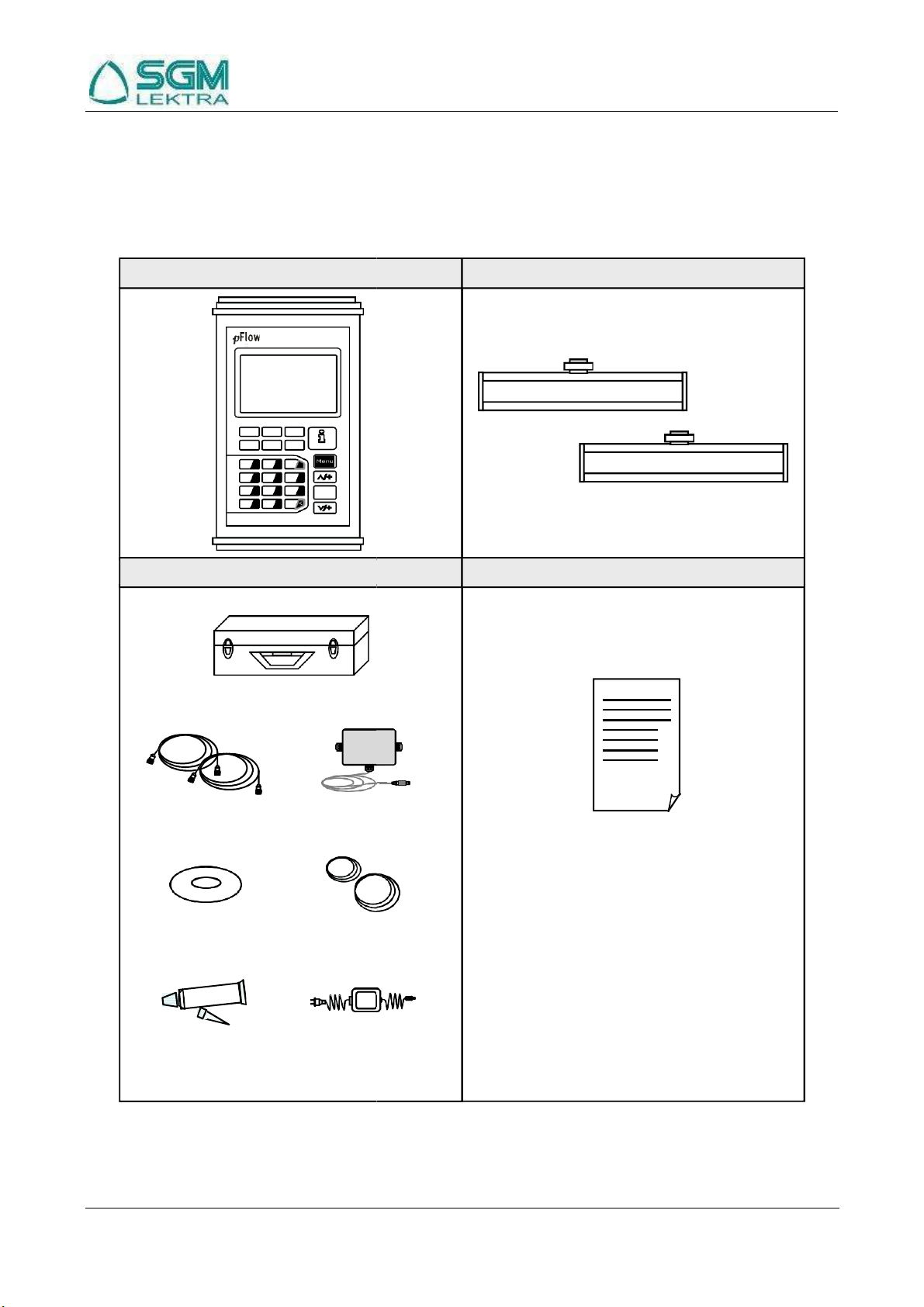
Carrying Case
Cable
Signal able
1.
Instruction
2.
Packing List
3.
Certified Factory Calibration
Software
Pipe Straps
Coupling Compound
Char er
Accessories
Documents
Product Components
Inspection should be made before installing the flowmeter. Check to see if the spare parts are in accordance with
the packing list. Make sure that there is no damage to the enclosure due to loose screw or wires or other damage
that may have occurred during transportation. Any questions, please contact your representative as soon as
possible.

SGM-101H Ultrasonic Flowmeter
www.sgm-lektra.com
Page 4 of 51
Content
1
Transmitter Installation and Connection ....................................................................................................6
1.1
Power Supply Connections ...................................................................................................................................................... 6
1.1.1
Type of Power Supply ..................................................................................................................................................... 6
1.1.2
Wiring.............................................................................................................................................................................. 6
1.1.3
Data Output Wiring ......................................................................................................................................................... 7
1.2
Powering On ............................................................................................................................................................................ 8
1.3
Keypad Functions..................................................................................................................................................................... 8
1.4
Keypad Operation .................................................................................................................................................................... 9
1.5
Flowmeter Menu Descriptions ............................................................................................................................................... 10
2
The Quick Setup Description......................................................................................................................11
2.1
Double Function Keys Menu Description.............................................................................................................................. 11
2.2
For example ........................................................................................................................................................................... 15
2.3
Measurement Site Selection ................................................................................................................................................... 17
3
Transducer Installation ...............................................................................................................................19
3.1
Installing the Transducer ........................................................................................................................................................ 19
3.1.1
Transducer Mounting Methods...................................................................................................................................... 19
3.1.2
V Method....................................................................................................................................................................... 19
3.1.3
Z Method ....................................................................................................................................................................... 19
3.1.4
N Method (not commonly used) .................................................................................................................................... 20
3.2
Transducer Installation and Fixing......................................................................................................................................... 20
3.3
Transducer Mounting Inspection ........................................................................................................................................... 20
3.3.1
Signal Strength .............................................................................................................................................................. 21
3.3.2
Signal Quality (Q value) ................................................................................................................................................ 21
3.3.3
Total Time and Delta Time............................................................................................................................................ 21
3.3.4
Transit Time Ratio ......................................................................................................................................................... 21
3.3.5
Warnings........................................................................................................................................................................ 21

SGM-101H Ultrasonic Flowmeter
www.sgm-lektra.com
Page 5 of 51
4
Operating Instructions ................................................................................................................................23
4.1
System Normal Identification ................................................................................................................................................ 23
4.2
Low Flow Cutoff Value ......................................................................................................................................................... 23
4.3
Zero Settings .......................................................................................................................................................................... 23
4.4
Scale Factor............................................................................................................................................................................ 23
4.5
4 ~ 20mA Current Loop Output............................................................................................................................................. 23
4.6
4~20mA Analog Output Calibration...................................................................................................................................... 24
4.7
TF Card Operation ................................................................................................................................................................. 24
4.7.1
Specifications................................................................................................................................................................. 24
4.7.2
Reading the TF Data Offline.......................................................................................................................................... 25
4.7.3
TF Card Storage Operation Guide ................................................................................................................................. 25
4.8
ESN........................................................................................................................................................................................ 26
5
Window Display Explanations....................................................................................................................27
5.1
Window Display Codes.......................................................................................................................................................... 27
5.2
Display Explanation............................................................................................................................................................... 28
6
Error Diagnoses ...........................................................................................................................................46
6.1
Table 1. Error Codes and Solutions (during operation).......................................................................................................... 46
6.2
Frequently Asked Questions and Answers............................................................................................................................. 47
7
Product Overview ........................................................................................................................................48
7.1
Introduction............................................................................................................................................................................ 48
7.2
Features of Flowmeter ........................................................................................................................................................... 48
7.3
Theory of Operation............................................................................................................................................................... 48
7.4
Applications ........................................................................................................................................................................... 49
7.5
Specifications......................................................................................................................................................................... 49
8
Appendix 1 - Flow Application Data ..........................................................................................................50
8.1
Sound Velocity and Viscosity for Fluids Commonly Used.................................................................................................... 50
8.2
Sound Velocity for Various Materials Commonly Used........................................................................................................ 50
8.3
Sound Velocity In Water (1 atm) At Different Temperatures................................................................................................ 51
Update Information:
SGM-101H Ultrasonic Flowmeter
www.sgm-lektra.com
Page 6 of 51
1
Transmitter Installation and Connection
1.1
Power Supply Connections
1.1.1
Type of Power Supply
The factory offers one rechargeable 11.1V Lithium battery and matching battery charger.
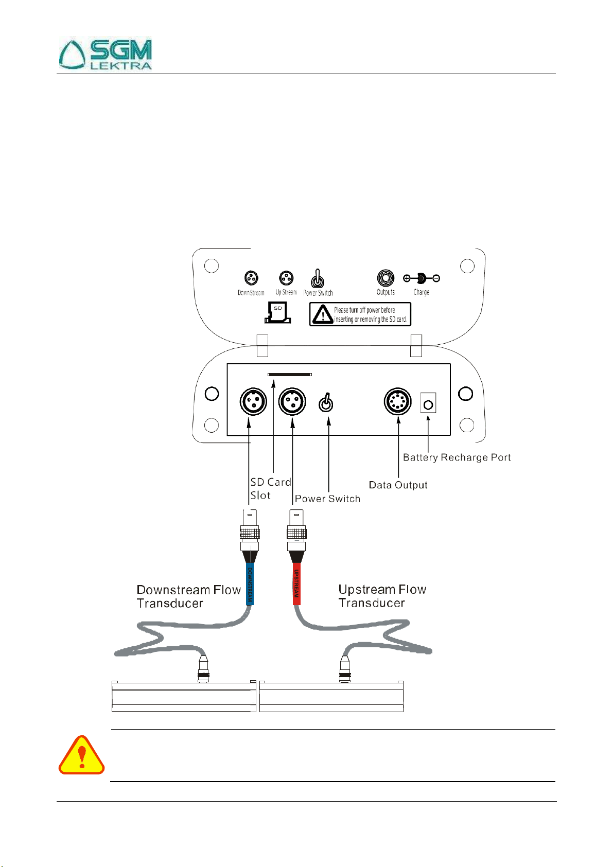
1.1.2
Wiring
Open the hinged top cover of the electronics. The wiring ports of the SGM-101H, from left to right, are as follows:
Downstream transducer connector, upstream transducer connector, SD card slot, power switch, data output
connector and battery recharge port.
Warning
Wiring connections should be made when power is off.

SGM-101H Ultrasonic Flowmeter
www.sgm-lektra.com
Page 7 of 51
n
RS485 and 4~20mA
Output
1.1.3
Data Output Wiring
Data output wiring as shown below: First connect the 8-pin plug with the data output port; after these connect the
AB with the RS485 Communication, finally get the I with the 4 ~ 20mA current output.
Data output port to
the tra smitter(8-pin)
A B I+ I-
OCT+ OCT- RL1 RL2

SGM-101H Ultrasonic Flowmeter
www.sgm-lektra.com
Page 8 of 51
1.2
Powering On
When the meter is powered on, it will start with the following screen, the Version Number Ver:1.01 and the Serial
number S/N:v5200355 will be shown at the bottom right corner.
If it is the first time of use or an installation on a new site, the customer needs to input the new installation site
parameters. Any parameters which are set by the user will be saved permanently until they are ch nged by the
user.
When the user modifies the parameters or removes the transducers, the meter will recalculate automatically, and
operate normally with the newly set parameters.
1.3
Keypad Functions
Follow these guidelines when using the flowmeter keypad:
~ and : Inputnumbers.
: Backspace or delete characters to the left.
and : Return to the last Menu or
open the next Menu. Acts as "+" and "-" are used to
enter numbers.
: Select a Menu. Press this key first, input a
two-digit Menu number and the selected Menu data
will be displayed. For example, in order to input a
pipe outside diameter, press
where "11" is the window ID to display the
pipe outside diameter.
: Enter / Confirm.
: Enter / Exit SD card storage interface.
、、、、、are shortcuts to the windows for Flow Rate,
Velocity, Signal Quality, POS Totalizer, waveform, and Diagnosis.

SGM-101H Ultrasonic Flowmeter
www.sgm-lektra.com
Page 9 of 51
1.4
Keypad Operation
The instrument setup and measurement displays are subdivided into more than 100 independent Menus. The
operator can input parameters, modify settings or display measurement results by "visiting" a specific Menu.
These Menus are arranged by 2-digit serial numbers from 00~99, then using +0, +1, etc. Each Menu ID code has a
defined meaning. For example, Menu 11 indicates the pipe outside diameter, while Menu 25 indicates the
mounting spacing between the transducers. Each Menu will be discussed later in this manual.
1.To visit a specific Menu, press the key at any time except the SD Card Storage Interface, then input the
2-digit Menu ID code and that Menu will be displayed. For example, to input or check the pipe outside diameter,
press the keys for window ID code 11.
Another method to visit a particular Menu is to press the , and keys to scroll through the
Menus. For example, if the current Menu is 30, press key to enter Menu 31, press the
again to enter Menu 30.
The Menus are divided into three types: 1) Data Type, such as M11, M12; 2) Selection Type, suc
Display Type, such as M00, M01.
Visit Data Type Menus to check specific parameters.
If parameter change is needed, just press
button
as M14; 3)
first, then input the values and press to
confirm.
Example 1: To enter a pipe outer diameter of
200mm, the procedure is as follows:
Press to enter Menu11 (the
numerical value displayed currently is the previous
pipe outer diameter). Now press the key. The
symbol ">" and a flashing cursor is displayed on the
screen.The new value can now be entered.
Visit Selection Type Menus to check the related
options. If need to modify it, press firstto
enter the revised selection when the symbol ">" is
displayed on the screen; or input numbers directly to
select the option when the symbol ">" and a flashing
cursor are displayed.
Example 2: If the pipe material is "Carbon Steel",
press to enter Menu 14,
then press to modify the option. Then,
select"0. Carbon Steel" from the drop-down Menu
( you may cycle through the choices by pressing the
and keys ) and then press
to confirm the selection.
SGM-101H Ultrasonic Flowmeter
www.sgm-lektra.com
Page 10 of 51
1.5
Flowmeter Menu Descriptions
These windows are assigned as follows:
00~09 Display Menus: Used to display flow rate, positive total, negative total, net total, velocity, date
& time etc.
10~29 Setup Menus: Used to enter pipe outer diameter, pipe wall thickness, fluid type, transducer
type, transducer mounting and spacing, etc.
30~38 Flow units selection and totalizer operating Menus: Used to select units of measurement. Other Menus set
/ reset the various totalizer modes.
40~45 Setup Menus: Zero Set Calibration menu, Scale Factor menu, etc.
46~81 Input and output setup Menus: current loop mode select, 4mA or 20mA output value, etc.
90~96 Diagnostics: signal strength quality (Menu 90), TOM/TOS*100 (Menu 91), sound velocity
(Menu 92), total time and delta time of the measured signal (Menu 93), Reynolds number and
K factor (Menu 94).
-0 4~20mA correction Menu.
Attention
"Hidden" Menus are for hardware adjustment (retained by the manufacturer).
SGM-101H Ultrasonic Flowmeter
www.sgm-lektra.com
Page 11 of 51
2
The Quick Setup Description
2.1
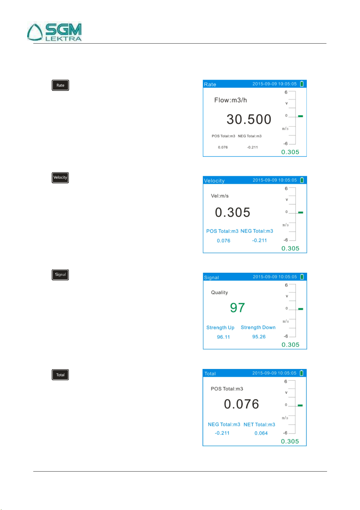
Double Function Keys Menu Description
Press to display Flow Rate with large font.
Press to display Velocity with large font.
Press to display Signal Quality with large font.
Press to display POS Total with large font.

SGM-101H Ultrasonic Flowmeter
www.sgm-lektra.com
Page 12 of 51
Menu 3 0
Press to display Metric/English.The function is
the same with .
Press to display the Current State of the
System.
Press to display Pipe Outside Diameter. The
function is the same with .
Press to display Pipe Wall Thickness. The
function is the same with .
SGM-101H Ultrasonic Flowmeter
www.sgm-lektra.com
Page 13 of 51
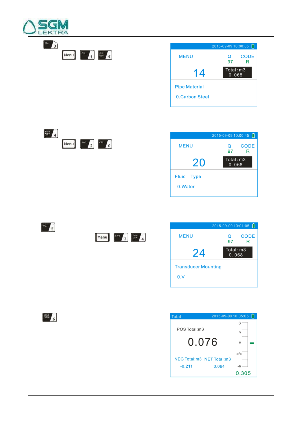
Press to display Pipe Material. The function is
the same with .
Press to display Fluid Type. The function is
the same with .
Press to display Transducer Mounting Methods.
The function is the same with .
Press to Start / Stop Manual Accumulation
Total in turn.

SGM-101H Ultrasonic Flowmeter
www.sgm-lektra.com
Page 14 of 51
Press to Display / Hold Total in turn.
Press to display TOM/TOS. The function is
the same with .
Press to display Fluid Sound Velocity. The
function is the same with .
Press to display Date and Time. The function
is the same with .
SGM-101H Ultrasonic Flowmeter
www.sgm-lektra.com
Page 15 of 51
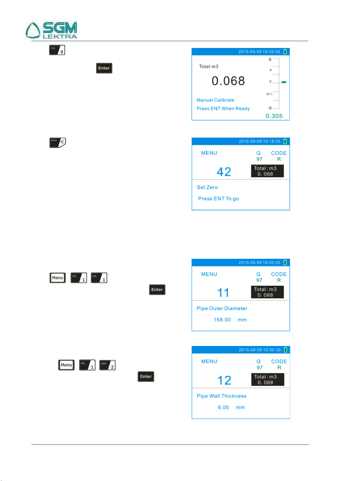
Press to enter Manual Calibrate.After the flow
velocity becomes steady, input standard totalizer to get
the K factor. Then press to complete the
calibration.
Press to input the password 1234 to reset zero.
2.2
For example
For Example: Let us assume you have a DN150 (6") pipe, measuring medium is water, Material is carbon steel
with no liner. These parameters should be operated as follows:
Step 1. Pipe Outer Diameter
Press keys to enter Menu 11,
enter the Pipe Outside Diameter, then press the
key.
Step 2. Pipe Wall Thickness
Press the key to enter Menu
12 the Pipe Wall Thickness, then press the
key.

SGM-101H Ultrasonic Flowmeter
www.sgm-lektra.com
Page 16 of 51
Step 3. Pipe Material
Press the key to enter Menu
14, press the key, use the or
key to select the pipe material from the drop-down
Menu, then press the key.
Step 4. Liner Material Parameters
(including thickness and sound velocity, if needed ):
Press the key to enter Menu
16, press the key, use the or
key to select liner material from the drop-down Menu,
and then press the key.
Step 5. Fluid Type
Press the key to enter Menu
20, press the key, use the or
key to select fluid type from the drop-down Menu, then
press the key.
Step 6. Transducer Mounting
Press the key to enter Menu
24, press the key, use the or
key to select transducer-mounting from the drop-down
Menu, then press the key.
( Details on Chapter 3.1.1 ).
SGM-101H Ultrasonic Flowmeter
www.sgm-lektra.com
Page 17 of 51
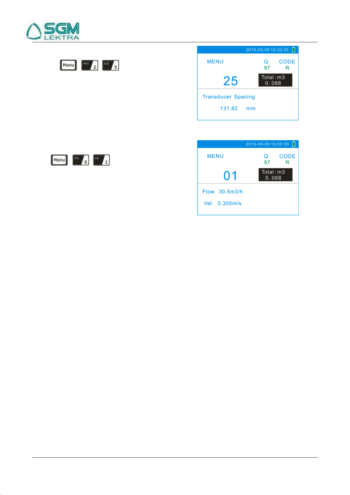
Step 7. Transducer Spacing
Press the key to enter Menu
25, accurately install the transducer according to the
displayed transducer mounting spacing and the selected
mounting method.
( Details on Chapter 2.3 ).
Step 8. Display Measurement Results
Press to enter Menu 01 to
display flow rate. ( Subject to the real measurement. )
2.3
Measurement Site Selection
Compared with other kinds of flowmeters, Ultrasonic Flowmeter is the simplest one to install. Choose a proper
measurement site, enter the pipe’s parameters into the flowmeter. Install and fix the transducers on the pipe as
instructed by the meter and start the measurement.
When selecting a measurement site, it is important to select an area where the fluid flow profile is fully developed
to guarantee a highly accurate measurement. Use the following guidelines to select a proper installation site:
Choose a section of pipe that is always full of liquid, such as a vertical pipe with flow in the upward direction
or a full horizontal pipe.
Ensure enough straight pipe length at least equal to the figure shown below for the upstream and downstream
transducers installation.
On the horizontal pipe, the transducer should be mounted on the 3 o’clock and 9 o’clock position of the pipe
section, avoid the 6 o’clock and 12 o’clock position, in order to avoid the signal attenuation caused by the
sediment at the bottom, or air bubbles or cavitation.
Ensure that the pipe surface temperature at the measuring point is within the transducer temperature limits.
Consider the inside condition of the pipe carefully. If possible, select a section of pipe where the inside is
free of excessive corrosion or scaling.
Choose a section of sound conducting pipe.

SGM-101H Ultrasonic Flowmeter
www.sgm-lektra.com
Page 18 of 51
D
P
L ≥10D
L ≥50D
10D min
Diffuser
L ≥30D
L≥5D
Name
Straight length of upstream
piping
Straight length of
downstream piping
Tee
Reduce
L≥10D
L ≥5D
Valve
L≥30D
L≥10D
Pump
Check valve
Stop valve
L≥50D
Flow controlled downstream
Flow controlled upstream
5D min
L ≥5D
Detector
L ≥10D
90
o
bend
10D min
0.5D min
10D min

SGM-101H Ultrasonic Flowmeter
www.sgm-lektra.com
Page 19 of 51
F
l
o
w
3
Transducer Installation
3.1
Installing the Transducer
Before installing the transducers, clean the pipe surface where the transducers are to be mounted. Remove any rust,
scale or loose paint and make a smooth surface. Choose a section of sound conducting pipe for installing the
transducers. Apply a wide band of sonic coupling compound down the center of the face of each transducer as
well as on the pipe surface, ensure there are no air bubbles between the transducers and the pipe wall, and then
attach the transducers to the pipe with the straps provided and tighten them securely.
Note:
1. The two transducers should be mounted at the pipe’s centerline on horizontal pipes. Make sure that the
transducer mounting direction is parallel with the flow.
2. During the installation, there should be no air bubbles or particles between the transducer and the pipe wall.
On horizontal pipes, the transducers should be mounted in the 3 o’clock and 9 o’clock positions of the pipe
section in order to avoid any air bubbles inside the top portion of the pipe.
3. Refer to 2.15 for the Transducer Mounting Spacing.
4. If the transducers cannot be mounted horizontally symmetrically due to limitation of the local installation
conditions, it may be necessary to mount the transducers at a location where there is a guaranteed full pipe
condition (the pipe is always full of liquid).
3.1.1
Transducer Mounting Methods
Three transducer mounting methods are available. They are respectively: V method, Z method and N method.
The V method is primarily used on small diameter pipes (DN100~300mm, 4"~12"). The Z method is used in
applications where the V method cannot work due to poor signal or no signal detected. In addition, the Z method
generally works better on larger diameter pipes (over DN300mm, 12") or cast iron pipes.
The N method is an uncommonly used method. It is used on smaller diameter pipes (below DN50mm, 2").
3.1.2
V Method
The V method is considered as the standard method. It usually gives a more accurate reading and is used on pipe
diameters ranging from 25mm to 400mm (1" ~ 16") approximately. Also, it is convenient to use, but still requires
proper installation of the transducers, contact on the pipe at the pipe’s centerline and equal spacing on either side
of the centerline.
Side View
Section
Top View
Upstream Transducer
Downstream Transducer
Transducer
Pipe Strap
Flow
Transducer Space
3.1.3
Z Method
The signal transmitted in a Z method installation has less attenuation than a signal transmitted with the V
method
when the pipes are too large, there are some suspended solid in the fluid, or the scaling and liner are too thick .
This is because the Z method utilizes a directly transmitted (rather than reflected) signal which transverses the
liquid only once. The Z method is able to measure on pipe diameters ranging from 100mm to 5000mm (4" to
200") approximately. Therefore, we recommend the Z method for pipe diameters over 300mm (12" ).

SGM-101H Ultrasonic Flowmeter
www.sgm-lektra.com
Page 20 of 51
F
l
o
w
F
l
o
w
Side View
Section
Top View
Upstream Transducer
Downstream Transducer
Transducer
Pipe Strap
Flow
Transducer Spacing
3.1.4
N Method (not commonly used)
With the N method, the sound waves traverse the fluid three times and bounce twice off the pipe walls. It is
suitable for small pipe diameter measurement. The measurement accuracy can be improved by extending the
transit distance with the N method ( uncommonly used ).
Side View
Section
Top View
Upstream Transducer
Downstream Transducer
Transducer
Pipe Strap
Flow
Transducer Spacing
3.2
Transducer Installation and Fixing
Transducers can be installed onto the pipe with its magnetic racks. If you need to fasten them, then you can use
the chains to make it firm. Show as below:
3.3
Transducer Mounting Inspection
Confirm the transducer is installed properly by checking the detected signal strength, total transit time, delta time
as well as transit time ratio Key 9.
The "mounting" condition directly influences the flow value accuracy and system long-term operation reliability.
In most instances it is only necessary apply a wide band of sonic coupling compound lengthwise on the face of the
transducer and stick it to the outside pipe wall to get good measurement results. However, the following checks
still need to be carried out in order to ensure a high reliability of the measurement and long-term operation of the
instrument.
Table of contents
Other SGM LEKTRA Measuring Instrument manuals

SGM LEKTRA
SGM LEKTRA SGM-101F Guide

SGM LEKTRA
SGM LEKTRA RPmag Guide

SGM LEKTRA
SGM LEKTRA RPmag Guide

SGM LEKTRA
SGM LEKTRA MUXM User manual

SGM LEKTRA
SGM LEKTRA SGM-100F User manual

SGM LEKTRA
SGM LEKTRA FLOWMETER User manual

SGM LEKTRA
SGM LEKTRA Pmag User manual

SGM LEKTRA
SGM LEKTRA Transit Time SGM-200H Guide


