manuals.online logo
Brands
  1. Home
  2. •
  3. Brands
  4. •
  5. YOKOGAWA
  6. •
  7. Measuring Instrument
  8. •
  9. YOKOGAWA PR300 Manual

YOKOGAWA PR300 Manual

Startup
Manual
1
IM 77C01E01-03E
2nd Edition: Sep. 2017 (YK)
Model PR300
Power and Energy Meter
<Initial Setup Operations>
1. Set up the PR300 First
NOTE
If you change the phase and wire system and the voltage range, all parameters other than those related to RS-485 and Ethernet communications are
initialized (to factory-set values). Change the phase and wire system and the voltage range before setting parameters such as the VT and CT ratios.
1.1 Setting the Phase and Wire System
This section explains how to set the phase and wire system by taking as an example the case when a three-phase four-wire system is changed to a three-
phase three-wire system.
Thank you for purchasing the PR300.
This manual describes the setting procedures of phase and wire system,
voltage range, VT ratio, and CT ratio of the PR300. The electronic manual is
also provided in this manual. Read them along with this manual.
To ensure correct use, be sure to read the PR300 Power and Energy Meter
User's Manual (IM 77C01E01-01E) thoroughly before beginning operation.
Printed manuals
Model PR300 Power and Energy Meter Startup Manual <Installation>
:
IM 77C01E01-02E
Model PR300 Power and Energy Meter Startup Manual <Initial Setup Operations> :
IM 77C01E01-03E (This manual)
Electronic manuals (PDF files)
Model PR300 Power and Energy Meter User’s Manual :
IM 77C01E01-01E
Model PR300 Power and Energy Meter Communication Interface User’s Manual:
IM 77C01E01-10E
Please keep this manual for future reference.
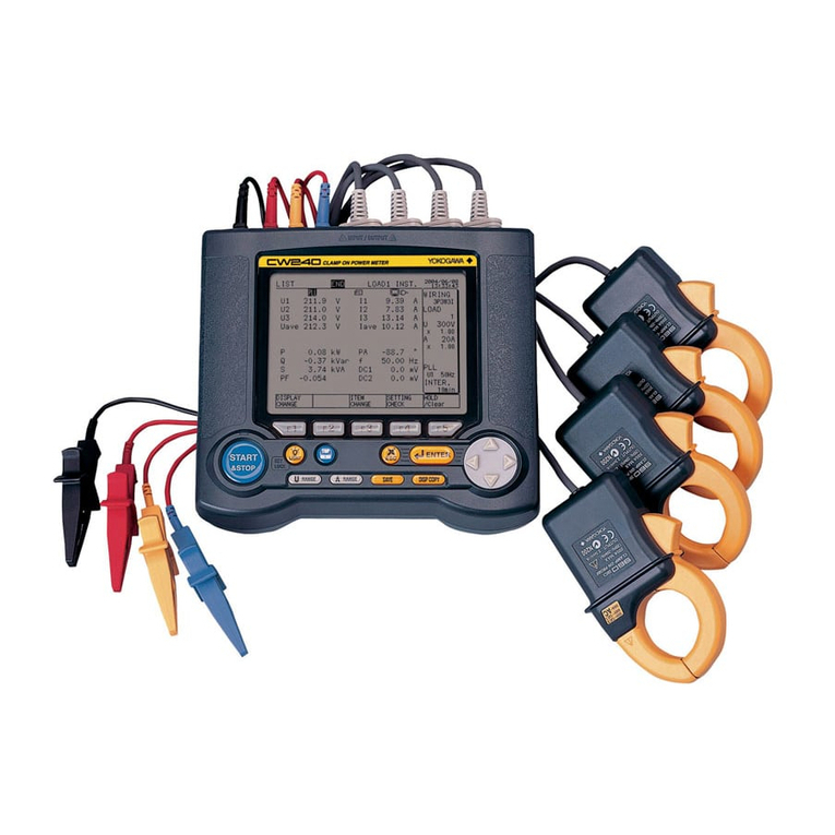
Component Names and Functions
Power lamp (Green)
Phase Indication lamps (Red)
MAX and MIN lamps (Red)
Demand Alarm lamp (Red)
Pulse Output lamp (Green)
Phase and Wire System lamps (Green)
Input Range lamps (Green)
Measured Value display (Red)
Unit lamps (Red)
Lights up and remains lit when the PR300 is
turned on and operating normally. Blinks (4
times/second) if a communication error
occurs, and continues to blink until the
PR300 returns to normal.
DEMAND lamp (Red)
Lights up when the measured value of demand
power or demand current is displayed.
(Only supported for a PR300 with the demand
measuring function.)
Light up to tell for which phase the voltage or
current value is being measured.
Light up when the maximum or minimum
measured value is displayed.
Operation keys
On the Measured Value screen, this key is
used, for example, to switch the display
pattern. Also used to set parameters on the
Parameter screen.
On the Measured Value screen, this key is used, for example, to
switch the phase of voltage/current. Also used to set parameters
on the Parameter screen.
This key is used to start or stop demand measure-
ment. The lamp (green) in the key lights up in the de-
mand measurement.On the Measured Value screen, this key is used, for example,
to move from one digit to another in an energy reading. Also
used to set parameters on the Parameter screen.
On the Measured Value screen, this key is used, for example, to show
the maximum/minimum value. Also used to set parameters on the
Parameter screen.
Lights up if the demand value exceeds the demand alarm point at
any point in time other than the demand alarm mask time.
Lights up when the output is turned on in the pulse output
mode and goes out when the output is turned off.
Communication lamp (Green)
Blinks while RS-485 or Ethernet communi-
cation is in progress.
The phase and wire system option set in the
PR300 lights up.
The voltage range option set in the PR300 and
the current range (rated input) option specified
at the time of ordering light up.
Shows a measured value of power, energy, etc.
Also shows a parameter symbol and its setpoint
at the time of parameter setting.
Show the unit symbol of a measured value for
each measurement item. These unit symbols
are shown in combination depending on the type
of measured value.
Turn on the PR300.
The Specification Change Confirmation screen appears.
Measured Value screen
Startup screen
VT Ratio screen
2
1
3
Phase and Wire System screen
6
Specification Change Confirmation screen
4
The PR300 shows the station number for about 5
seconds, then the Measured Value screen * appears.
Phase and Wire System Setting screen
7
The Phase and Wire System Setting screen appears.
5
Phase and Wire System Setting screen
8
Hold down for at least 3 seconds.
Simultaneously hold down
+for at least 3 seconds.
Using or , show on
the lower display.
Press once.
The Phase and Wire System screen appears.
Setpoint
The parameter (VT ratio) appears.
Current value
Parameter symbol for
phase and wire system
Press once.
Using or , select the setpoint.
Press once to blink the setpoint.
Phase and Wire System screen
Phase and Wire System Setting screen
Measured Value screen
The PR300 shows the Startup screen for about 5 seconds,
then the Measured Value screen appears.
The setpoint is confirmed and the PR300
returns to the Phase and Wire System screen.
Setting completed.
When proceeding to set the voltage range, start from Step
6in Section 1.2, “Setting the Voltage Range,” with this
screen (figure on the left) shown as is.
Current value
10
Hold down for at least 3 seconds.
To re-set the parameter:
Press any key other than
while all digits of the setpoint are blinking.
The PR300 returns to the initial setting screen.
9
Press once while the setpoint is blinking.
Note
•If single-phase three-wire system is selected, the voltage
range is fixed at 300V (between P0 and P1, P0 and P2). The
voltage range cannot be selected.
•Three-phase four-wire system (2.5 element) can be used only
when the voltage is in a state of equilibrium. In addition, the
phase and wire system cannot be changed.
Range of Phase and Wire System Options
Parameter Symbol
Parameter Name
Setting
Type Setting Range (Details) Initial Value
(Factory-set
Value)
Phase and
wire system
Selection Model and Suffix Codes
Model and Suffix Codes
Single-phase
two-wire system
Single-phase
three-wire system
Three-phase
three-wire system
Single-phase
two-wire system
Single-phase
three-wire system
Three-phase
three-wire system
Three-phase
four-wire system
Three-phase four-wire
system (2.5 element)
Three-phase
three-wire
system
Three-phase
four-wire
system
Model and Suffix Codes Three-phase
four-wire system
(2.5 element)
* The initial value of the Measured Value screen (display pattern) is Upper
display: Current (phase switch indication), Middle display: Voltage (phase
switch indication), and Lower display: Active power. For the display
pattern setting procedures, refer to the PR300 Power and Energy Meter
User's Manual (IM 77C01E01-01E).
Record the parameter settings of the PR300 on MEMO column in
Appendix 4, “Parameter List” of the user’s manual (IM 77C01E01-01E).
Note that in the case of a failure, the parameter settings set to the failed
product cannot be restored.
You can download the latest manuals from the following website.
https://www.yokogawa.com/ns/pr300/im/
2
IM 77C01E01-03E 2nd Edition Sep. 29, 2017
1.2 Setting the Voltage Range
This section explains how to set the voltage range by taking as an example the case when the voltage range is changed from 300 V to 600 V.
Using or , show the Voltage
Range screen.
The Specification Change Confirmation screen
appears.
Measured Value screen
Startup screen
VT Ratio screen
2
1
3
Phase and Wire System screen
6
Specification Change Confirmation screen
4
The PR300 shows the station number for about 5
seconds, then the Measured Value screen * appears.
The Phase and Wire System screen appears.
7
The Voltage Range screen appears.
The Voltage Range Setting screen appears.
5
8
9
Voltage Range screen
Voltage Range Setting screen
Turn on the PR300.
Hold down for at least 3 seconds.
The parameter (VT ratio) appears.
Using or , show on
the lower display.
Press once.
Press once.
Current value
Parameter symbol for voltage range
Setpoint
Simultaneously hold down
+for at least 3 seconds.
Press once to blink the setpoint.
Using or , select the setpoint.
2. Setting the VT and CT Ratios
NOTE
Set the VT and CT ratios so that the value of “secondary rated
power ⴛVT ratio ⴛCT ratio”is smaller than 10 GW. If this value
exceeds 10 GW, the updated VT or CT ratio will not be
incorporated but revert to the current value before change.
2.1 Setting the VT Ratio
This section explains how to set the VT ratio by taking as an example the
case when the VT ratio is changed from the initial value (1) to 4.
Prior to proceeding to the following steps, ensure that the PR300 is turned
on, and the Measured Value screen is displayed.
1
Measured Value screen
VT Ratio screen
1
2
VT Ratio Setting screen
VT Ratio screen
3
4
If you do not operate any key for more than 5
minutes on the Parameter screen, the PR300
automatically returns to the Measured Value screen.
Setting completed.
Hold down for at least 3 seconds.
The parameter (VT ratio) appears.
Current value
Press once.
The screen changes to the one for setting the
parameter and the alterable digit blinks.
Using or , change the setpoint.
Setpoint
To move to the digit to be changed, use the following
keys:
To the left
To the right
Press once to blink the setpoint.
5
To return to the Measured Value screen, hold down
.
When proceeding to set the CT ratio, press once
and start from step 3in Section 2.2, “Setting the CT Ratio.”
Press once while the setpoint is blinking.
The setpoint is confirmed and the PR300 returns to the VT Ratio screen.
To re-set the parameter:
Press any key other than while all digits of the setpoint are
blinking. The PR300 returns to the initial setting screen.
Parameter (VT Ratio) Setting Types and Ranges
Parameter Symbol
Parameter Name Setting Type Setting Range (Details) Initial Value
(Factory-set
Value)
VT ratio
Integral
numeric
value
1 to 6000 1
2.2 Setting the CT Ratio
This section explains how to set the CT ratio by taking as an example the
case when the CT ratio is changed from the initial value (1.00) to 10.00.
Prior to proceeding to the following steps, ensure that the PR300 is turned
on, and the Measured Value screen is displayed.
To return to the Measured Value screen, hold down
.
Measured Value screen
VT Ratio screen
1
2
3
CT Ratio screen
5
CT Ratio Setting screen
The alterable digit blinks.
6
CT Ratio Setting screen
CT Ratio screen Setting completed.
CT Ratio Setting screen
4
Current value
Setpoint
Hold down for at least 3 seconds.
The parameter (VT ratio) appears.
Press once.
The parameter (CT ratio) appears.
Press once.
The screen changes to the one for setting the parameter
and the decimal point blinks.
Press once to fix the position of the decimal point.
To move the decimal point, use the following keys:
To the left To the right
Using or , change the setpoint.
To move to the digit to be changed, use the following keys:
To the left To the right
To re-set the parameter:
Press any key other than while all digits of the setpoint are
blinking. The PR300 returns to the initial setting screen.
If you do not operate any key for more than 5
minutes on the Parameter screen, the PR300
automatically returns to the Measured Value screen.
Press once to blink the setpoint.
7
Press once while the setpoint is blinking.
The setpoint is confirmed and the PR300 returns to the CT Ratio screen.
Parameter (CT Ratio) Setting Types and Ranges
Parameter Symbol
Parameter Name Setting
Type Setting Range (Details)
Initial Value
(Factory-set
Value)
CT ratio
Floating-point
numeric
value
1.000.05 to 32000
Voltage Range Setting screen
11
Measured Value screen
Setting completed.
Voltage Range screen
When proceeding to set the phase and wire system, press
or to show the Phase and Wire System screen,
with this screen (figure on the left) shown as is. After
showing the Phase and Wire System screen, start from step
6
in Section 1.1, “Setting the Phase and Wire System.”
Hold down for at least 3 seconds.
10
To re-set the parameter:
Press any key other than
while all digits of the setpoint are blinking.
The PR300 returns to the initial setting screen.
Press once while the setpoint is blinking.
The PR300 shows the Startup screen for about 5 seconds,
then the Measured Value screen appears.
The setpoint is confirmed and the PR300 returns to the
Voltage Range screen.
NOTE
•The voltage range of single-phase three-wire system is fixed at
300V (between P0 and P1, P0 and P2). The voltage range
cannot be selected.
•Select the voltage range of three-phase four-wire system, by
the phase voltage (between P0 and P1, P0 and P2, P0 and P3).
Range of Voltage Range Options
Parameter Symbol
Parameter Name
Setting
Type Setting Range (Details) Initial Value
(Factory-set
Value)
Voltage range
Selection 150V
300V
600V
300V
* The initial value of the Measured Value screen (display pattern) is Upper
display: Current (phase switch indication), Middle display: Voltage (phase
switch indication), and Lower display: Active power. For the display
pattern setting procedures, refer to the PR300 Power and Energy Meter
User's Manual (IM 77C01E01-01E).

Other manuals for PR300

3

Other YOKOGAWA Measuring Instrument manuals

YOKOGAWA 960 30 User manual

YOKOGAWA

YOKOGAWA 960 30 User manual

YOKOGAWA ADMAG TI Series User manual

YOKOGAWA

YOKOGAWA ADMAG TI Series User manual

YOKOGAWA OX100 User manual

YOKOGAWA

YOKOGAWA OX100 User manual

YOKOGAWA AQ7260 OTDR User manual

YOKOGAWA

YOKOGAWA AQ7260 OTDR User manual

YOKOGAWA DX Series Release note

YOKOGAWA

YOKOGAWA DX Series Release note

YOKOGAWA PBDH1000 User manual

YOKOGAWA

YOKOGAWA PBDH1000 User manual

YOKOGAWA 765501 User manual

YOKOGAWA

YOKOGAWA 765501 User manual

YOKOGAWA SC21 Series User manual

YOKOGAWA

YOKOGAWA SC21 Series User manual

YOKOGAWA AQ6151B User manual

YOKOGAWA

YOKOGAWA AQ6151B User manual

YOKOGAWA US300PM User manual

YOKOGAWA

YOKOGAWA US300PM User manual

YOKOGAWA FLXA402T User manual

YOKOGAWA

YOKOGAWA FLXA402T User manual

YOKOGAWA MV100 User manual

YOKOGAWA

YOKOGAWA MV100 User manual

YOKOGAWA RAGN Manual

YOKOGAWA

YOKOGAWA RAGN Manual

YOKOGAWA Powercert UZ005 User manual

YOKOGAWA

YOKOGAWA Powercert UZ005 User manual

YOKOGAWA TR User manual

YOKOGAWA

YOKOGAWA TR User manual

YOKOGAWA AQ2180 User manual

YOKOGAWA

YOKOGAWA AQ2180 User manual

YOKOGAWA CA12E HANDY CAL User manual

YOKOGAWA

YOKOGAWA CA12E HANDY CAL User manual

YOKOGAWA FLXA202 User manual

YOKOGAWA

YOKOGAWA FLXA202 User manual

YOKOGAWA MT300 Guide

YOKOGAWA

YOKOGAWA MT300 Guide

YOKOGAWA AQ6360 User manual

YOKOGAWA

YOKOGAWA AQ6360 User manual

YOKOGAWA AQ6370C User manual

YOKOGAWA

YOKOGAWA AQ6370C User manual

YOKOGAWA Total Insight series User manual

YOKOGAWA

YOKOGAWA Total Insight series User manual

YOKOGAWA 800 plus Use and care manual

YOKOGAWA

YOKOGAWA 800 plus Use and care manual

YOKOGAWA PBL5000 User manual

YOKOGAWA

YOKOGAWA PBL5000 User manual

Popular Measuring Instrument manuals by other brands

Co2meter AQ500 manual

Co2meter

Co2meter AQ500 manual

Bin Master 1000 Installation and operating instructions

Bin Master

Bin Master 1000 Installation and operating instructions

FRO­NIUS Smart Meter TS 65A-3 operating instructions

FRO­NIUS

FRO­NIUS Smart Meter TS 65A-3 operating instructions

HANYOUNG NUX HP3 instruction manual

HANYOUNG NUX

HANYOUNG NUX HP3 instruction manual

Isotech PLTC-782 User's operation manual

Isotech

Isotech PLTC-782 User's operation manual

S.E. International URSA II Operation manual

S.E. International

S.E. International URSA II Operation manual

Co2meter eSENSE Outdoor SE-0036 installation manual

Co2meter

Co2meter eSENSE Outdoor SE-0036 installation manual

AquaLab 4TE Series quick start

AquaLab

AquaLab 4TE Series quick start

Delta OHM LPPYRA02 operating manual

Delta OHM

Delta OHM LPPYRA02 operating manual

Master cool 52236 instruction manual

Master cool

Master cool 52236 instruction manual

Aquametro CALEC ST Mounting and operating instructions

Aquametro

Aquametro CALEC ST Mounting and operating instructions

Powerline S4BL instruction manual

Powerline

Powerline S4BL instruction manual

Dilog DL6506 operating manual

Dilog

Dilog DL6506 operating manual

Abus TVVR33602 Instructions for user

Abus

Abus TVVR33602 Instructions for user

A/DA ZVE 160 operating manual

A/DA

A/DA ZVE 160 operating manual

Ecotech HiVol 3000 user manual

Ecotech

Ecotech HiVol 3000 user manual

Delta HD2114P.0 operating manual

Delta

Delta HD2114P.0 operating manual

Master cool 53100-C User Guide and Parts List

Master cool

Master cool 53100-C User Guide and Parts List

manuals.online logo
manuals.online logoBrands
  • About & Mission
  • Contact us
  • Privacy Policy
  • Terms and Conditions

Copyright 2025 Manuals.Online. All Rights Reserved.