SGM LEKTRA Pmag User manual

Pmag GB
Pmag
Electromagnetic flowmeter
Features
• Pipe dimension range: DN10 ÷ DN1000
• Measure range: <0,2m3/h ÷ >30000m3/h
• Fluid conductivity: >5
S/cm
• Sensor material: SS321
• Lining materials: PTFE from DN10 to DN500;
rubber from DN40 to DN1000
• Housing materia: epoxy printing aluminum
• Electrodes materials: SS316; Hastelloy C
• Remote version operating temperature:
<80°C
• Compact version operating temperature:
-20÷75°C
• Accuracy: ±0,5%
• Repeatability: ±0,1%
• Analog outpu: 4÷20mA; max. load 750
• Communication protocol: Modbus (opt.)
• Digital output: 0÷5000Hz
• Pulse output: 24Vdc pull-up
• Alimentazione: 85÷265Vac or 24Vdc
• Consumption: <6W
• Protection compact version: IP67 with 4 cable
gland M16x1,5 for elect. connection
• Protection remote version: IP67/IP68 only pipe
(opt.)
• Display: backlit LCD
forward and reverse flow rate
direct, reverse and net total
General
A complete magnetic flowmeter system consists of two components: the Smag62 microprocessor-based integral-mount
magneti flowmeter transmitter and a flowtube.The flowtube is installed in-line with process piping, either vertically
or horizontally. Coils located on opposite sides of the flowtube create a magnetic field, and conductive liquid moving
through the magnetic field generates a voltage that is detected by two electrodes.The transmitter controls the generation
of the magnetic field and senses the voltage detected by the electrodes. Based on the sensed voltage, the transmitter
calculates a flow rate and produces analog and frequency output signals proportional to this flow rate.
Compactdigitalsystem,forconductiveliquids(>5
S/cm),
even with a limitated content of suspended solids.
Measurement range: from <0,2m3/h to >30000m3/h
Typical measurement accuracy: ±0.5%
Power supply 85÷265Vac or 24Vdc

Page 2 of 24
Pmag62 - Features
1. Features
1.1 Flow Rate Range
Capable of processing signals from fluids that are traveling between to 10 m/s for both forward and reverse flow in all
flowtube sizes..
1.2 Fluid Conductivity
Fluid must have conductivity of at least 5 microsiemen/cm.
1.3 Power Supply
85 ÷ 265Vac or 24Vdc depending on the model.
1.4 Consumption
Typical 6W, max. 8W.
1.5 Ambient Temperature Limits
Operating: -20÷75°C (-4÷167°F).
Storage: -40÷85°C (-40÷185°F).
1.6 Output Signals
4÷20mA: 0÷750 ohm load.
Frequency : 0÷5000 Hz
Pulse: ability to set the pulse width, output H or L status and connect the internal pull-up resistor through JP1
1.7 Reverse Flow
Instantaneous and totalized reverse flow measure.
1.8 Output Testing
Current Source: Transmitter can be commanded to supply a specified current between 4.0 and 20.0 mA.
Frequency Source: Transmitter can be commanded to supply a specified frequency between 0.1 and 10000 Hz.
1.9 Start-up Time
0.5 seconds from zero flow.
1.10 Low Flow Cutoff
Adjustable between 0.0 and 9.9%Qmax. Below selected value, output is driven to the zero flow rate signal level.
1.11 Humidity Limits
0÷100% RH a 65 °C (150 °F), senza condensazione.
1.12 Damping
Adjustable between 0.1 and 99 seconds.
2. TECHNICAL DATA
2.1 Accuracy
System accuracy is ±0.5% of rate from 0.2 to 10 m/s.
2.2 Repeatability
± 0,1% of reading
2.3 Response Time
0.2 seconds maximum.
2.4 Stability
±0.1% of rate over six months.

Page 3 of 24
Pmag - Features
005NDot3NDmorfegnarwolF
)dradnats.nim01ND(
0002NDot006NDmorfegnarwolF
)0001ND.xamdradnats(
3. FLOW TABLES

Page 4 of 24
Pmag - Features
4. DIMENSION
4.1 Compact version
ND .P )mm(eziseniltuO )mm(ezisegnalF
thgieW
)mm( )aPM( a b c e D D
0
n A )gK(
01 0.4 002 243 09 01 06 4 41 6
51 0.4 002 243 59 51 56 4 41 6
02 0.4 002 243 501 02 57 4 41 6
52 0.4 002 023 511 52 58 4 41 7
23 0.4 002 043 041 23 001 4 81 9
04 0.4 002 743 051 04 011 4 81 01
05 0.4 002 063 561 05 521 4 81 21
56 3.1 002 593 581 56 541 4 81 71
08 6.1 002 593 002 08 061 8 81 71
001 6.1 052 504 022 001 081 8 81 22
521 6.1 052 514 052 521 012 8 81 42
051 6.1 003 574 582 051 042 8 22 53
002 0.1 053 335 043 002 592 8 22 54
052 0.1 054 785 593 013 052 053 21 32 48
003 0.1 005 756 544 013 003 004 21 32 201
053 0.1 055 747 505 054 053 064 61 32 321
004 0.1 006 197 565 054 004 515 61 62 741
054 0.1 006 718 516 054 054 565 02 62 212
005 0.1 006 798 076 054 005 026 02 62 902
006 0.1 006 869 087 016 006 527 02 03 252
007 0.1 007 0701 598 016 007 048 42 03 253
008 0.1 008 7611 5101 016 008 059 42 53 264
009 0.1 009 7621 5111 007 009 0501 82 53 055
0001 0.1 0001 7731 0321 007 0001 0611 82 53 086

Page 5 of 24
Pmag - Features
4.2 Remote version
ND .P )mm(eziseniltuO )mm(ezisegnalF
thgieW
)mm( )aPM( a b c e D D
0
n A )gK(
01 0.4 002 542 09 01 06 4 41 4
51 0.4 002 542 59 51 56 4 41 4
02 0.4 002 542 501 02 57 4 41 4
52 0.4 002 322 511 52 58 4 41 5
23 0.4 002 342 041 23 001 4 81 7
04 0.4 002 052 051 04 011 4 81 8
05 0.4 002 362 561 05 521 4 81 01
56 3.1 002 892 581 56 541 4 81 51
08 6.1 002 892 002 08 061 8 81 51
001 6.1 052 803 022 001 081 8 81 02
521 6.1 052 813 052 521 012 8 81 22
051 6.1 003 773 582 051 042 8 22 33
002 0.1 053 534 043 002 592 8 22 34
052 0.1 054 094 593 013 052 053 21 32 28
003 0.1 005 065 544 013 003 004 21 32 001
053 0.1 055 946 505 054 053 064 61 32 121
004 0.1 006 396 565 054 004 515 61 62 541
054 0.1 006 027 516 054 054 565 02 62 012
005 0.1 006 008 076 054 005 026 02 62 702
006 0.1 006 078 087 016 006 527 02 03 052
007 0.1 007 279 598 016 007 048 42 03 053
008 0.1 008 0701 5101 016 008 059 42 53 064
009 0.1 009 0711 5111 007 009 0501 82 53 055
0001 0.1 0001 0821 0321 007 0001 0611 82 53 086

Page 6 of 24
Figure 2-1 PMAG transmitter dimensions
Pmag - Installation
5. INSTALLATION
5.1 Safety measure
Instructions and procedures in this section may require special precautions to ensure the safety of the personnel performing
the operations. Information that raises potential safety issues is indicated by a warning symbol . Please refer to the
following safety messages before performing an operation preceded by this symbol.
5.2 WARNINGS
5.2.1 Explosions could result in death or serious injuryi
- Verify that the operating atmosphere of the flowtube and transmitter is consisten with the appropriate hazardous
locations certifications.
- Do not remove the transmitter cover in explosive atmospheres when the circuit is alive.
- Before connecting a HART-based communicator in an explosive atmosphere, make sure the instruments in the
loop are installed in accordance with intrinsically safe or non-incendive field wiring practices.
- Both transmitter covers must be fully engaged to meet explosion-proof requirements.
5.2.2 Failure to follow safe installation and servicing guidelines could result in death or serious injury
- Make sure only qualified personnel perform the installation.
- Do not perform any service other than those contained in this manual unless qualified.
5.2.3 High voltage that may be present on leads could cause electrical shock
- Avoid contact with leads and terminals.
5.3 PRE-INSTALLATION
There are several pre-installation steps that make the installation process easier. They include identifying the options and
configurations that apply to your application, setting the hardware switches if necessary, and consideration of mechanical,
electrical, and environmental requirements. Please remember that the flowtube liner is vulnerable to handling damage.
Never place anything through the flowtube for the purpose of lifting or gaining leverage.Liner damage can render the flowtube
useless.
5.3.1 Identify Options and Configurations
Standard application of the Pmag includes control of the flowtube coils and one or more following configurations or
options:
- 4÷20 mA Output
- Pulse Output
Be sure to identify the options and configurations that apply to your situation, and keep a list of them nearby during
the installation and configuration procedures.
5.3.2 Mechanical Considerations
The mounting site for the Pmag Integral Mount Transmitter should provide enough room for secure mounting,
easy access to the conduit ports, full opening of the transmitter covers, and easy readability of the local operator
interface (LOI) screen (see Figure 2-1).The LOI can be rotated in 90° increments. This should be performed prior
to installing the magnetic flowmeter system.

Page 7 of 24
5.4 Requirement for electric connection
Before making any electrical connections to the Pmag, consider the following standards and be sure to have proper power
supply, conduit, and other accessories.
5.4.1 Conduit Connections
The Pmag Integral Mount Magnetic Flowmeter Transmitter has 4 M16*1.5 conduit connections.
5.4.2 Transmitter Input Power
The Pmag Transmitter is designed to be powered by voltages ranging 85÷265Vac (50 a 60 Hz), 24Vac or 24Vdc.
5.4.3 DC Power Requirements
Units powered with 24Vdc may draw up to 2 amps of current. As a result, the input power wire must meet certain
gauge requirements.
5.4.4 Disconnects
The supply wires should be connected to the device through an external disconnect or circuit breaker. The disconnect
or circuit breaker should be clearly labeled and located near the transmitter.
5.4.5 Overcurrent Protection
Pmag requires overcurrent protection of the supply lines. Maximum rating of overcurrent devices are as follows:
Pmag - Installation
5.5 ENVIRONMENTAL CONSIDERATIONS
To ensure maximum transmitter life, avoid excessive heat and vibration.Typical problem areas include high-vibration lines
with integrally Mounted transmitters, warm-climate installations in direct sunlight, and outdoor installations in cold
climates. Because the Pmag System requires external power, access to a suitable power source must be ensured.
Overheating will damage the flowtube. Do not encapsulate the flowtube with heating elements
5.6 Mounting
Electric magnetic flow meter has a flanged connector, and meets standard UNI EN 1092-1 ( Ex UNI 2223).
5.7 Environment of the installation
1) The Pmag must by mounted in dry and well ventilated site. Not install the instrument in the place where the water is easily accumulated.
2) The instrument should not be exposed. Shelter is needed where the instrument is installed outside.
3) Vibration should be avoided in the place where the instrument is to be installed.
4) Keep the instrument away from strong magnetic field where big electric motor or transformer are installed.
5) The place where the instrument is installed shall be accessible for maintenance
5.8 Selecting the place for installation
1) The arrow mark on the sensor must be in accordance with the medium flow direction in the pipeline.
2) The sensor must be full with the medium all the time.
3) The straight length of the upstream pipeline must not be less than 5xD, and the downstream 3x3D, where D is the
inner diameter of the pipe, and the middle of the sensor can be a point of the lengths

Page 8 of 24
Pmag - Installation
5.9 Grounding
The grounding of the instrument must be satisfied because the signal the instrument
measured is very weak, only a few milli-voltages, even at its full range. See figure 9
for the grounding position. There are two requirements for grounding:
1) The sensor and the fluid must be equipotential.
2) Special grounding fitting must be assembled when electromagnetic disturbance
is greater. Total section area of the wires for grounding shall be greater than 4mm2
with multicore threads of copper. Grounding wire cannot be connected on electric
motor or common grounding's for all other equipment in case of the influence
occurred from any electric current leakage.
The resistance of grounding shall be less than 10 ohm. See figure 9.
The sensor must be assembled with grounding rings or flanges on its both sides, or a short pipe on which there is an
electrode for grounding when the sensor shall be installed on plastic pipeline or the pipeline has insulated liner.
5.10 Preparation for operation
Strictly check the installment and wirings before it gets into operation!
It shall be pointed out that the instrument, including the sensor and converter has been fully adjusted, calibrated
with actual flow, and inspected under strict measures. All shipped units are certified. No further adjustments
are required when put it into operation. Observing the contents in this manual, to check and analyze any
malfunction
The following steps are to be followed to get the instrument into operation.
1) Make sure that the sensor is completely filled with fluid.
2) Turn on the power supply. One minute late, the value displayed in the indicator will reach some amount, which
means the connections of wires are correct. If the flow direction is wrong, then change the flow direction on the
converter..
3) Zero verification. Shut off the valve tight in downstream first and then the valve in upstream, to let the medium in the
pipeline stops. The displayed value should be 0. The value displayed can be corrected at the converter if the value is
different than 0: ensure that no leaks.
Figure 9

Page 9 of 24
Pmag - Connection
6. ELECTRIC CONNECTION
6.1 Install Conduit
Transmitter junction boxes have n.4 M16*1.5 conduit connections.
Seal unused ports to prevent moisture or other contamination from entering the junction box.
Do not overtighten metal plugs used to seal wiring compartment ports,overtightening can damage the housing.
6.2 Power Connections
To connect power to the transmitter, complete the following steps:
1) Open the power terminal cover.
2) Run the power cable through the conduit to the transmitter.
3) Loosen the terminal cable guard for the input power terminals L and N or + and -.
4) Connect the power cable leads as follows:
For an AC-powered transmitter (fig.2-13):
- Connect AC Ground to a grounding lug.
- Connect AC Neutral to terminal N.
- Connect AC Line to terminal L.
For a DC-powered transmitter (fig.2-13):
- Connect DC Ground to a grounding lug.
- Connect + DC.
- Connect - DC.
6.3 OUTPUT
Satisfy these requirements before attempting to install and operate the Pmag.
6.3.1 Analog output
The loop may be powered from the transmitter itself. Resistance in the loop must be 750ohms or less.
6.3.2 Digital output
The digital output, if set frequency mode generates an output signal from 0 to 5000Hz Max. proportional to flow rate,
if set in pulse mode generates an output signal in relation to totaled volume increasing. The signal is normally used in
conjunction with an external totalizer or control system. complete the following steps to connect the signal cable to
the transmitter:
1) Run the signal cable into the transmitter.
2) Connect the two wires that convey switch closure information to the F+ and F- terminals
6.3.3 RS485 serial output
In models with RS485 option can communicate via Modbus . Connect the serial cable to terminals A + and B-
.Neriw noitcnuF lanimreT
seriw-owT
elbac
4 1.nlioC X
5 2.nlioC Y
seriw-eerhT
elbac
1 1.nedortcelE A
2 dleihS/dnuorG C
3 2.nedortcelE B
6.4 Remote version
To connect the sensor to the transmitter respect the matching cables.:

Page 10 of 24
Pmag - Quick start-up
7. QUICK START-UP
7.1 Transmitter
Check that the analog range of the transmitter matches the analog range in the control system.
7.2 Flowtube
1. For horizontal flow installations, ensure that the electrodes are in a plane such that they remain covered by process
fluid.
2. For vertical or inclined installations, ensure that process fluid is flowing up into the flowtube to keep the electrodes
covered by process fluid.
3. Ensure that the grounding straps on the flowtube are connected to grounding rings, lining protectors, or the adjacent
pipe flanges. Improper grounding will cause erratic operation of the system.
7.3 Process Fluid
1. The process fluid conductivity must be greater than 5 microS.
2. Process fluid must be free of air and gasses.
Completed the mechanical installation and electrical connections, the PMAG is ready to start. May still be necessary
to verify the units ("Units PV" / "Total Units") and the 100% flow value (Qmax (m3 / h) ") in accordance with plant
requirements.
8. LOCAL OPERATOR INTERFACE (LOI)
The LOI option is an operator communications center for the Pmag. Through the LOI, the operator can access any
transmitter function for changing configuration parameter settings, checking totalized values, or other functions.
8.1 SAFETY MESSAGES
Instructions and procedures in this section may require special precautions to ensure the safety of the personnel performing
the operations. Information that raises potential safety issues is indicated by a warning symbol: .
Please refer to the following safety messages before performing an operation preceded by this symbol.
8.2 WARNINGS
Explosions could result in death or serious injury
- Verify that the operating atmosphere of the flowtube and transmitter is consistent with the appropriate hazardous
locations certifications.
- Do not remove the transmitter cover in explosive atmospheres when the circuit is alive.
- Before connecting a HART-based communicator in an explosive atmosphere, make sure the instruments in the loop
are installed in accordance with intrinsically safe or non-incendive field wiring practices.
- Both transmitter covers must be fully engaged to meet explosion-proof requirements.
Failure to follow safe installation and servicing guidelines could result in death or serious injury
- Make sure only qualified personnel perform the installation.
- Do not perform any service other than those contained in this manual unless qualified
High voltage that may be present on leads could cause electrical shock
- Avoid contact with leads and terminals
8.3 LOI FEATURES
The LOI option contains a four-line, 16-character liquid
crystal display (LCD) that is back-lit and visible from
any angle. There are four touch keys on the pad,
and a infrared decoder to receive keys that on the
remote encoder.Table 3-1 lists and details the
functions of the LOI keys.

Page 11 of 24
8.4 LOI ROTATION
Each magnetic flowmeter installation is different from application to application; therefore, the LOI display can be rotated to
accommodate various setups using the following procedure:
1. Remove power from the transmitter
2. Unscrew and remove the LOI cover. Do not remove the cover in explosive atmospheres when the circuit is
alive.
3. Unfasten the 4 screws that attach the LOI assembly to the main circuit assembly.
4. Carefully remove the LOI assembly by pulling it away from the transmitter.
5. Position the LOI in a preferred 90° rotation.
6. Fasten the 4 screws that attach the LOI to the main circuit assembly.
7. Replace the LOI cover
8.5 DATA ENTRY
The LOI keypad has no numerical keys. Enter numerical data using the following procedure:
1. Access the appropriate function.
2. Use to highlight the digit you want to enter or change.
3. Use or to change the highlighted value.
For numerical data, or toggles through the digits 0÷9,decimal point; For alphabetical data, they toggle through
the letters of the alphabet A-Z, digits 0÷9, and the symbols &, +, -, *, /, $, @, %, and the blank space ( or is
also used to toggle through pre-determined choices that do not require data entry.).
4. Use to highlight and change other digits you want to change.
5. Press to confirm the insertion of data.
Pmag - Setting

Page 12 of 24
8.7 LOI MENU
Press the key from run mode: the display will show the list of configuration menu as
shown here next.
Press the or keys to select the desired menu, then press the key to access
Pmag - Setting
8.6 DISPLAY PAGE
The Pmag has three pages to display data and status, press or to change page
If there is no alarm,
this page will not appear
Page 12 of 24

Page 13 of 24
Pmag - Setting
PV Units variable specifies the format in which the flow rate will be displayed.
Default: m3/h. Range: L/s; m3/s; G/s; L/m; m3/m; G/m; L/h; m3/h; G/h.
Press the key from run mode: the display will be as shown here next.
With or select the unit.
Press to confirm, the display will be as shown here next.
press the key to exit and confirm the selection; press the key to exit and delete
the selection.
8.7.1.2 - PV Decimal
PV Decimal specifies how many decimals are displayed after the decimal point.
Default: 3
Range: 1÷3
Press the key from run mode: the display will be as shown here next.
With or select the decimal number places to display.
Press to confirm, the display will be as shown here next.
press the key to exit and confirm the selection; press the key to exit and delete
the selection.
8.7.1.3 - Total Units
Total Units specifies the counter display unit
Default: m3
Range: L, Litri; m3, Metri cubi; G, galloni
Press the key from run mode: the display will be as shown here next.
With or select the counter display unit
Press to confirm, the display will be as shown here next.
press the key to exit and confirm the selection; press the key to exit and delete
the selection.
8.7.1.4 - Total Decimal
Total Decimal specifies how many decimals are displayed after the decimal point.
Default: 3
Range: 1÷3
8.7.1 Basic Configuration (Basic)
Press the key from run mode: the display will be as shown here next, then press
to enter the "Basic" menu
Press the or keys to select the desired function and press the key to access
8.7.1.1 - PV Units

Page 14 of 24
8.7.1.5 - Damping (s)
Damping(S) sets the delay time in seconds for changes in reading. It 'used to mitigate
the fluctuations in flow measurement.
Default: 1; Range: 0.1÷99.9
Press the key from run mode: the display will be as shown here next.
With or change the digit, with moves the cursor.
Press to confirm, the display will be as shown here next.
press the key to exit and confirm the selection; press the key to exit and delete
the selection.
8.7.2 System Configuration (System)
Press the key from run mode, then press the key to select "System" and press
the button to enter.
Press the or keys to select the desired function and press the key to access
To access the menu "System" may need to enter the correct password.
The default password: 0100
After entering, you can change the password
Note: If forget password can not access the menu.
8.7.2.1 - Language
Allows menu language selection.
Default: English
Press the key from run mode: the display will be as shown here next.
Press to confirm, the display will be as shown here next.
press the key to exit and confirm the selection; press the key to exit and delete
the selection.
8.7.2.2 - Signal
Press the key to enter the submenu "Signal"
Press the key from run mode: the display will be as shown here next.
With or select the decimal number places to display.
Press to confirm, the display will be as shown here next.
press the key to exit and confirm the selection; press the key to exit and delete
the selection.
Pmag - Setting

Page 15 of 24
8.7.2.2.1 - Qmax (m3/h)
Set the flow measurement 100%. This value adjusts the analog output end scale
(20mA) and the frequency output end scale.
The range is related to the sensor DN.
Press the key from run mode: the display will be as shown here next.
With or change the digit, with moves the cursor.
Press to confirm, the display will be as shown here next.
press the key to exit and confirm the selection; press the key to exit and
delete the selection.
8.7.2.2.2 - LowCutoff %
Low Cutoff specifies the Qmax% value below which the instantaneous flow
measurement reading (direct or reverse) and the outputs are forced to zero.
Default: 0.0 Range: 0.0÷9.9
Press the key from run mode: the display will be as shown here next.
With or change the digit, with moves the cursor.
Press to confirm, the display will be as shown here next.
press the key to exit and confirm the selection; press the key to exit and
delete the selection.
8.7.2.2.3 - Max Limit %
When the measure variation is lower than Max Limit%, or higher but with a lower time period
than that set in Limit Time (s), the measure is not detected. When the measure variation is
higher than Max Limit% and with a higher time period than that set in Limit Time (s), the
measure is detected. Default: 0.0; Range: 0.0÷9.9
Press the key from run mode: the display will be as shown here next.
With or change the digit, with moves the cursor.
Press to confirm, the display will be as shown here next.
press the key to exit and confirm the selection; press the key to exit and
delete the selection.
8.7.2.2.4 - Limit Time (s)
Sets the time limit used by the function Max Limit%.
Default: 00.0
Range: 00.0÷99.9
Press the key from run mode: the display will be as shown here next.
With or change the digit, with moves the cursor.
Press to confirm, the display will be as shown here next.
press the key to exit and confirm the selection; press the key to exit and
delete the selection.
Pmag - Setting

Page 16 of 24
8.7.2.2.5 - Direction
This parameter enables the flow direction measurement
Default: Fwd (forward)
Range: Fwd (forward); Rev (reverse); Bid. (bidirectional)
Press the key from run mode: the display will be as shown here next.
With or select the parameter setting.
Press to confirm, the display will be as shown here next.
press the key to exit and confirm the selection; press the key to exit and
delete the selection.
8.7.2.2.6 - Indication
Set what is the positive flow direction compared to the arrow on the sensor.
Default: Fwd (forward)
Range: Fwd (forward); Rev (reverse)
Press the key from run mode: the display will be as shown here next.
With or select the parameter setting.
Press to confirm, the display will be as shown here next.
press the key to exit and confirm the selection; press the key to exit and
delete the selection.
8.7.2.3 - Pulse Output
Press the key to enter the submenu “Pulse Output” .
8.7.2.3.1 - Freq Max (Hz)
Sets the maximum frequency in relation to Qmax. The digital output is active as a
frequency output only when the parameter "Liter / Pulse" is set to 0.0.
Default: 2000.0; Range: 100.0÷5000.0
Press the key from run mode: the display will be as shown here next.
With or change the digit, with moves the cursor.
Press to confirm, the display will be as shown here next.
press the key to exit and confirm the selection; press the key to exit and
delete the selection.
8.7.2.3.2 - Liter/Pulse
Set the volume per pulse. When this parameter is set to 0.0, the digital output is
active as a frequency output (see "Max Freq (Hz)").
Default: 0.0; Range: 0.0055÷max. according to the DN
Press the key from run mode: the display will be as shown here next.
With or change the digit, with moves the cursor.
Pmag - Setting

Page 17 of 24
Press to confirm, the display will be as shown here next.
press the key to exit and confirm the selection; press the key to exit and
delete the selection.
8.7.2.3.3 - Pulsewidth (ms)
Sets the pulse width in ms.
Default: 000.0;
Range: 0000.0÷1000.0
Press the key from run mode: the display will be as shown here next.
With or change the digit, with moves the cursor.
Press to confirm, the display will be as shown here next.
press the key to exit and confirm the selection; press the key to exit and
delete the selection.
8.7.2.3.4 - Pulse Level
Sets the pulse output energy level. When set LOW the pulse count is low, when set
HIGH, the pulse count is high.
Default: Active L (LOW); Range: Active L (LOW) ÷ Active H (HIGH)
Press the key from run mode: the display will be as shown here next.
With or select the parameter setting.
Press to confirm, the display will be as shown here next.
press the key to exit and confirm the selection; press the key to exit and
delete the selection.
8.7.2.4 - RS485 Output
Press the key to enter the submenu “RS485 Output” .
8.7.2.4.1 - RS Protocol
Sets the RS485 output communication protocol.
Default: MOD-BUS RTU
Range: MOD-BUS RTU ÷ MOD-BUS ASC
Press the key from run mode: the display will be as shown here next.
With or select the parameter setting.
Press to confirm, the display will be as shown here next.
press the key to exit and confirm the selection; press the key to exit and
delete the selection.
8.7.2.4.2 - Baud Rate
Sets the RS485 output Baud Rate.
Default: 9600
Range: 1200 - 2400 - 4800 - 9600
Pmag - Setting

Page 18 of 24
Pmag - Setting
Press the key from run mode: the display will be as shown here next.
With or select the parameter setting.
Press to confirm, the display will be as shown here next.
press the key to exit and confirm the selection; press the key to exit and
delete the selection.
8.7.2.4.3 - Data Bit
Sets the RS485 output Data Bit.
Default 8
Range: 8 - 7
Press the key from run mode: the display will be as shown here next.
With or select the parameter setting.
Press to confirm, the display will be as shown here next.
press the key to exit and confirm the selection; press the key to exit and
delete the selection.
8.7.2.4.4 - Parity
Sets the RS485 output Parity.
Default: NONE
Range: EVEN; ODD; NONE
Press the key from run mode: the display will be as shown here next.
With or select the parameter setting.
Press to confirm, the display will be as shown here next.
press the key to exit and confirm the selection; press the key to exit and
delete the selection.
8.7.2.4.5 - Stop Bit
Sets the RS485 output Stop Bit.
Default: 1
Range: 1 - 2
Press the key from run mode: the display will be as shown here next.
With or select the parameter setting.
Press to confirm, the display will be as shown here next.
press the key to exit and confirm the selection; press the key to exit and
delete the selection.
8.7.2.4.6 - Dev Address
Set the unity UID in RS485 network
Default: 001
Range: 001÷999

Page 19 of 24
Pmag - Setting
Press the key from run mode: the display will be as shown here next.
With or select the parameter setting.
Press to confirm, the display will be as shown here next.
press the key to exit and confirm the selection; press the key to exit and
delete the selection.
8.7.2.5 - Total Set
Press the key to enter the submenu “Total Set” .
8.7.2.5.1 - Password
To access the menu "Total Set" may need to enter the correct password.
The default password: 0020
After entering, you can change the password
Note: If forget password can not access the menu.
8.7.2.5.2 - Clear Total
Reset totalizer
Default: NO
Range: NO - YES
Press the key from run mode: the display will be as shown here next.
With or select the parameter setting.
Press to confirm, the display will be as shown here next.
press the key to exit and confirm the selection; press the key to exit and
delete the selection.
8.7.2.5.3 - FWD Preset
Predetermines the positive totalizer value
Default: 0000000000
Range: 1÷9999999999
Press the key from run mode: the display will be as shown here next.
With or change the digit, with moves the cursor.
Press to confirm, the display will be as shown here next.
press the key to exit and confirm the selection; press the key to exit and
delete the selection.

Page 20 of 24
8.7.2.5.4 - REV Preset
Predetermines the negative totalizer value
Default: 0000000000
Range: 1÷9999999999
Press the key from run mode: the display will be as shown here next.
With or change the digit, with moves the cursor.
Press to confirm, the display will be as shown here next.
press the key to exit and confirm the selection; press the key to exit and
delete the selection.
8.7.2.6 - Load Setting
Load factory settings.
Default: NO Range: YES - NO
Press the key from run mode: the display will be as shown here next.
With or select the parameter setting.
Press to confirm, the display will be as shown here next.
press the key to exit and confirm the selection; press the key to exit and
delete the selection.
8.7.3 Calibrations (Calibration)
Press the key from run mode, then press the key to select "Calibration" and
press the button to enter.
8.7.3.1 - Zero Trim
Zero flow measurement calibrate. The sensor must be full and the flow stopped.
Default: NO Range: YES - NO
Press the key from run mode: the display will be as shown here next.
With or select the parameter setting.
Press to confirm, the display will be as shown here next.
press the key to exit and confirm the selection; press the key to exit and
delete the selection.
8.7.3.2 - Tube Trim
Press the key to enter the submenu “Tube Trim” .
8.7.3.2.1 - Full Trim
Performs a full pipe recognition self calibration.
Default: NO
Range: NO - YES
Pmag - Setting
This manual suits for next models
1
Table of contents
Other SGM LEKTRA Measuring Instrument manuals

SGM LEKTRA
SGM LEKTRA MUXM User manual
SGM LEKTRA
SGM LEKTRA FLOWMETER User manual

SGM LEKTRA
SGM LEKTRA RPmag Guide
SGM LEKTRA
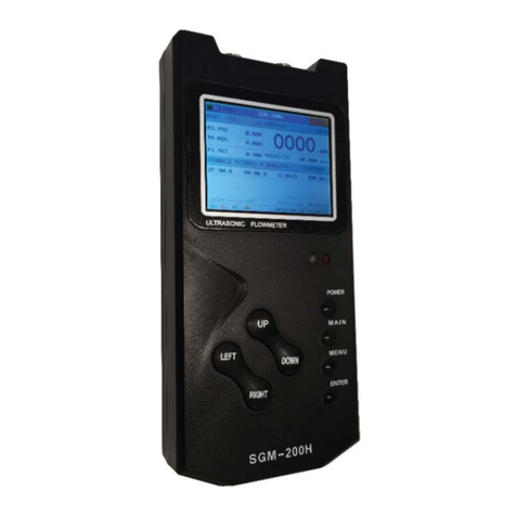
SGM LEKTRA Transit Time SGM-200H Guide

SGM LEKTRA
SGM LEKTRA RPmag Guide
SGM LEKTRA
SGM LEKTRA SGM-101H Guide
SGM LEKTRA
SGM LEKTRA SGM-101F Guide

SGM LEKTRA
SGM LEKTRA SGM-100F User manual

