THORLABS HPLS343 User manual

HPLS343 & HPLS345
High-Power Plasma Light
Sources with
Liquid Light Guides
User Guide

Plasma Light Sources with Liquid Light Guide
Table of Contents
Chapter 1 Warning Symbol Definitions.............................................................................................. 1
Chapter 2 Safety .................................................................................................................................... 2
Chapter 3 Description........................................................................................................................... 3
3.1. Overview ..........................................................................................................................3
3.2. Light Emitting Plasma.....................................................................................................3
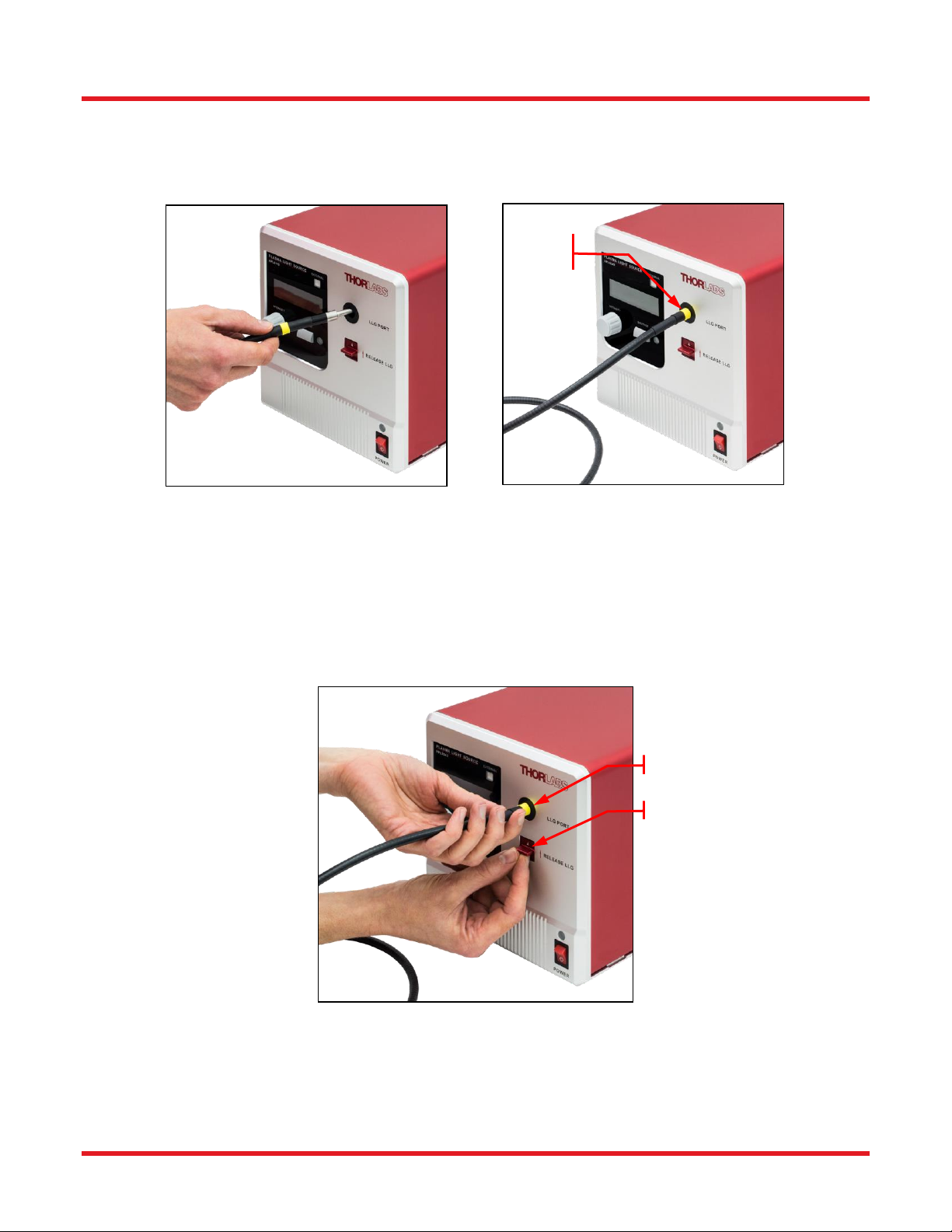
3.3. Liquid Light Guide...........................................................................................................4
3.4. Spectrum..........................................................................................................................4
Chapter 4 Setup ..................................................................................................................................... 5
4.1. Part List............................................................................................................................5
4.2. Operation Elements ........................................................................................................5
4.3. Initial Setup......................................................................................................................6
4.4. Connected Liquid Light Guide.......................................................................................6
4.5. Microscope Collimation Adapters .................................................................................8
Chapter 5 Operation.............................................................................................................................. 9
5.1. Starting the Light Source ...............................................................................................9
5.2. LCD Screen....................................................................................................................10
5.3. Shutter Operation..........................................................................................................10
5.4. Intensity Tuning.............................................................................................................10
5.5. External Control ............................................................................................................10
5.5.1. External Shutter Operation .................................................................................................. 11
5.5.2. ANALOG IN and TRIGGER IN ............................................................................................ 11
5.5.3. ANALOG OUT and TRIGGER OUT ................................................................................... 11
5.5.4. Signal Train ......................................................................................................................... 12
5.6. Operation Modes...........................................................................................................13
5.6.1. Open Loop Mode ................................................................................................................ 13
5.6.2. Closed Loop Mode .............................................................................................................. 13
5.6.3. Eco Mode ............................................................................................................................ 13
5.7. Stability and Noise ........................................................................................................14
5.8. Warning and Errors.......................................................................................................15
Chapter 6 Maintenance........................................................................................................................16
6.1. Fuse Replacement.........................................................................................................16
6.2. Bulb Module Replacement ...........................................................................................16
6.3. Firmware Update...........................................................................................................20
Chapter 7 Software GUI.......................................................................................................................21
Chapter 8 Command Line Operation.................................................................................................22
8.1. Command-Line Interface Overview .............................................................................22

Plasma Light Sources with Liquid Light Guide
8.2. Command Summary .....................................................................................................23
8.3. Description of Commands............................................................................................24
8.3.1. ? – Get Device Commands ................................................................................................. 24
8.3.2. *idn? or *IDN? – Device Information ................................................................................... 24
8.3.3. SN? – Device Serial Number .............................................................................................. 24
8.3.4. LSN? – Bulb Module Serial Number ................................................................................... 24
8.3.5. ST? – Device Status ........................................................................................................... 25
8.3.6. INT=n; INT? – Device Power Intensity ................................................................................ 25
8.3.7. SHT=n; SHT? – Shutter ...................................................................................................... 25
8.3.8. LAT? – Bulb Module Temperature ...................................................................................... 26
8.3.9. LLG? – Light Guide Temperature ....................................................................................... 26
8.3.10.MOD=n; MOD? – Device Control Mode .............................................................................. 26
8.3.11.LAD=n; LAD? – Operation Mode ........................................................................................ 27
8.3.12.LON=n; LON? – Bulb Module ON/OFF ............................................................................... 27
8.3.13.ERR? – Error message ....................................................................................................... 28
8.3.14.WAR? – Warning Message ................................................................................................. 28
Chapter 9 Specifications .....................................................................................................................29
Chapter 10 Mechanical Drawing...........................................................................................................30
Chapter 11 Certifications and Compliances.......................................................................................31
Chapter 12 Regulatory...........................................................................................................................33
Chapter 13 Thorlabs Worldwide Contacts..........................................................................................34

Plasma Light Sources with Liquid Light Guide Chapter 1: Warning Symbol Definitions
Rev F, June 12, 2019 Page 1
Chapter 1 Warning Symbol Definitions
Below is a list of warning symbols you may encounter in this manual or on your device.
Symbol
Description
Direct Current
Alternating Current
Both Direct and Alternating Current
Earth Ground Terminal
Protective Conductor Terminal
Frame or Chassis Terminal
Equipotentiality
On (Supply)
Off (Supply)
In Position of a Bi-Stable Push Control
Out Position of a Bi-Stable Push Control
Caution: Risk of Electric Shock
Caution: Hot Surface
Caution: Risk of Danger
Warning: Laser Radiation
Caution: Spinning Blades May Cause Harm

Plasma Light Sources with Liquid Light Guide Chapter 2: Safety
Page 2 CTN009142-D02
Chapter 2 Safety
The lamp comes with a switching power supply compatible with voltages from 100 to 240 VAC. There is no need
to change the fuse when selecting your regional voltage. If the user needs to change the fuse located below the AC
plug on the back of the unit, see section 6.1.
SHOCK WARNING
High voltage inside. To avoid electrical shock, before powering unit, make sure that the protective
conductor of the 3-conductor power cord is correctly connected to the protective earth contact of the
socket outlet. Improper grounding can cause electric shock resulting in severe injury or even death.
Do not operate without cover installed.
WARNING
This unit must not be operated in explosive environments.
CAUTION
Do not operate in wet/damp conditions.
WARNING
Do NOT look directly at the light source beam during operation. Do NOT place hand or body part in
the light beam as this may result in burns. NEVER place objects inside the LLG mount except for the
LLG tip, fully inserted.
CAUTION: HOT SURFACE
The housing of the lamp housing can get very hot during operation. Extended contact may result in
burns.
CAUTION: HOT SURFACE
The temperature of the lamp module will exceed 75 ˚C during operation. Always wait for at least 10
minutes for the light source to cool down before performing a lamp module replacement. Always wear
gloves when handling the lamp module.
CAUTION
When one tip of the liquid light guide is installed in the light source, do NOT put the dust cap on the
other tip of the LLG while the shutter is open. The dust cap may burn if exposed the intense light
emitted from the tip of the LLG.
WARNING
Always power off the unit before opening the housing.

Plasma Light Sources with Liquid Light Guide Chapter 3: Description
Rev F, June 12, 2019 Page 3
Chapter 3 Description
3.1. Overview
Thorlabs’ HPLS300 series plasma light sources combine the best features of solid-state electronics and full
spectrum plasma emitters. The Luxim® Light Emitting Plasma (LEP)™ bulb module uses a ceramic resonant cavity
to efficiently couple power from a solid-state power amplifier into a high-intensity discharge vessel. This technique
results in the long life of the bulb module (6000 hours typical operating time before the optical power output at given
driving current drops to 50% of the initial intensity) and produces a complete color spectrum. These light emitters
are ideal for applications such as endoscopy, microscopy, and other medical lighting and inspection applications.
3.2. Light Emitting Plasma
Thorlabs’ HPLS300 series light sources feature the Luxim® LEP™ bulb module which is an intense white light
source. The Luxim ® LEP™ lamp source generates a light emitting plasma using a bulb module, illustrated in Figure
1, that includes no electrodes. Instead, the electrical circuit generates an RF field that the ceramic resonator focuses
at the location of the quartz bulb. The plasma excited in the bulb produces light with a complete color spectrum. As
the bulb module does not include electrodes, it is efficient and has a long lifetime. The LEP™ bulb module consists
of two fundamental parts:
Emitter: A quartz bulb embedded in a ceramic resonator
Radio Frequency (RF) Driver: A solid-state RF generator and micro-controller.
A radio-frequency signal is generated and amplified by the RF driver, which is guided into the ceramic resonator.
The structure of the resonator concentrates the RF field, delivering energy to the fully-sealed quartz bulb without
electrodes or filaments. The highly concentrated electric field ionizes the gasses and vaporizes the halides in the
bulb - creating a plasma state at its center - resulting in an intense source of white light.
Figure 1 Architecture of a Plasma Light Source
Inside the back of the bulb, a diffuse yet highly reflective material is used to reflect all of this light to the forward
direction in a Lambertian pattern. The color of the light is tailored by the fill chemistry inside the lamp to provide
naturally white and high color rendering light.
By energizing a plasma arc without using filaments or electrodes, all failure modes and inefficiencies of traditional
broadband light sources are eliminated in an LEP™ lamp source, leaving behind an incredibly bright and stable
source with long life span comparable only to light emitting diodes (LEDs).

Plasma Light Sources with Liquid Light Guide Chapter 3: Description
Page 4 CTN009142-D02
3.3. Liquid Light Guide
In Thorlabs’ HPLS343 and HPLS345 light sources, the high power white light output from the plasma emitter is
coupled into and then delivered through a 3 mm core and 5 mm core liquid light guide, respectively.
The liquid light guide (LLG) can be thought of as an optical fiber with a very large core size. A key difference between
LLGs and conventional optical fibers is that the core of the LLG consists of a non-toxic and non-flammable liquid.
The liquid is sealed inside a polymer tube with silica tips on both ends. The LLG offers a large core size and high
NA, and its transmission window includes the entire visible spectrum. Thus an LLG are is a powerful tool to deliver
the intense light output from the HPLS343 and HPLS345 light sources.
When the LLG is inserted and the light sources are operating, the HPLS343 and HPLS345 actively monitor the
temperature of the tip of the light guide and cool as necessary to prevent it from overheating. This assures the
maximum life span of the liquid light guide is achieved.
3.4. Spectrum
Figure 2 Typical Output Spectrum of the HPLS343/345
The HPLS343 and HPLS345 light sources provide a full color spectrum from 350 nm to 800 nm. Figure 2 shows a
typical output spectrum of an HPLS343 and HPLS345 light source, measured at the output tip of the liquid light
guide.

Plasma Light Sources with Liquid Light Guide Chapter 4: Setup
Rev F, June 12, 2019 Page 5
Chapter 4 Setup
4.1. Part List
The package contains the following items:
One Light Source
One Liquid Light Guide
One Flash Drive with Software and the Operation Manual
One USB2.0 A-B Cable, 2 m Long
One Region-Specific Power Cord
One 3 mm Hex Key
One 2 mm Hex Key
4.2. Operation Elements
Figure 3 Front and Back Panel of the HPLS343/HPLS345 Light Sources
F1. External Control Button with LED
F2. LCD Screen
F3. Shutter Control Button
F4. Light Intensity Adjustment Knob
F5. Liquid Light Guide Port
F6. Liquid Light Guide Release Switch
F7. Shutter State LED
F8. Light Source State Indicator LED
F9. Power Switch
B1. BNC Port for External Shutter Control: 5 V CMOS
B2. SMA Port for Trigger OUT: 5 V CMOS
B3. BNC Port for Analog IN: 0 to 5 V
B4. BNC Port for Trigger IN: 5 V CMOS
B5. SMA Port for Analog OUT: 0 to 5 V
B6. USB Port
B7. AC Power Inlet
B8. Fuse Drawer

Plasma Light Sources with Liquid Light Guide Chapter 4: Setup
Page 6 CTN009142-D02
4.3. Initial Setup
Take the light source out of its packaging and place it onto a table. The two feet closest to the front panel can be
flipped open to change the viewing angle of the front panel.
The light source also has four slots, located at the four bottom corners. As shown in Figure 4, by using Thorlabs
table clamp CL6 or CL8, together with one of Thorlabs' baseplates, one can securely mount the plasma light source
onto the surface of an optical table or breadboard with 1/4"-20 or M6 threaded mounting holes.
Figure 4 HPLS343/345 Mounted on a Breadboard Using CL6 Table Clamp and BA2S6 Baseplate
4.4. Connected Liquid Light Guide
The HPLS343 and HPLS345 light sources include with a 3 mm or 5 mm core liquid light guide (LLG), respectively.
Both sizes are shown in Figure 5.
Figure 5 A 3 mm Core LLG (Left) and a 5 mm Core LLG (Right)

Plasma Light Sources with Liquid Light Guide Chapter 4: Setup
Rev F, June 12, 2019 Page 7
To install the LLG in the light source, first remove the red dust caps from the tips of the LLG. Take the end that has
a yellow marking ring on it and insert it to the LLG port in the front panel of the light source. The marking ring visually
indicates when the LLG is inserted to the correct depth. It is fully inserted when the edge of the yellow band is flush
with the front panel, as shown in Figure 6.
Figure 6 Insert the LLG into the Light Source
We highly recommend using the LLGs featuring the yellow marking ring with these light sources, though all of
Thorlabs’ standard liquid light guides are compatible, taking core diameter into consideration. When using an LLG
that does not have the marking ring, there is the risk that the light guide may not be inserted to the proper depth
during installation.
To remove the LLG, lightly press the LLG release switch upwards and pull out the light guide. This is shown in
Figure 7.
Figure 7 Remove the LLG
NOTE: Liquid light guides are sensitive items that require caution for proper handling. Any grease, dust or scratches
on the light guide tip may cause damage to the light guide during operation. Please always keep the dust cap on
whenever the light guide is not in use.
Pull Out
Push Up
Fully
Inserted

Plasma Light Sources with Liquid Light Guide Chapter 4: Setup
Page 8 CTN009142-D02
4.5. Microscope Collimation Adapters
Thorlabs offers collimation adapters with AR-coated aspheric condenser lenses (EFL = 40 mm) for collimating the
output from the HPLS343 and HPLS345 light sources. Four different collimator housings are available; each is
designed to mate to the illumination port on an Olympus IX/BX, Leica DMI, Zeiss Axioskop, or Nikon Eclipse Ti
microscope. These collimation adapters are sold separately on the Thorlabs website.
Compatible
Microscopes
Olympus BX & IX
Microscopes
Leica DMI
Microscopes
Zeiss Axioskop
Microscopes
Nikon Eclipse Ti
Microscopes
Item Photo
Item #
LLG3A1-A
LLG5A1-A
LLG3A2-A
LLG5A2-A
LLG3A4-A
LLG5A4-A
LLG3A5-A
LLG5A5-A
LLG Core
Diameter
3 mm
5 mm
3 mm
5 mm
3 mm
5 mm
3 mm
5 mm
These adapters can be quickly mounted onto the end of a liquid light guide. The LLG is secured into the back of
the collimator using a setscrew. With these collimation adapters, users can easily couple the white light output from
an HPLS343 or HPLS345 light source to either the epi-illumination or the trans-illumination port of the compatible
microscopes above. The broadband spectrum, high brightness, and high color rendering index of these light sources
makes them ideal for both fluorescence and bright field microscopy.

Plasma Light Sources with Liquid Light Guide Chapter 5: Operation
Rev F, June 12, 2019 Page 9
Chapter 5 Operation
SHOCK WARNING
High voltage inside. To avoid electrical shock, before powering unit, make sure that the protective
conductor of the 3-conductor power cord is correctly connected to the protective earth contact of the
socket outlet. Improper grounding can cause electric shock resulting in severe injury or even death.
Do not operate without cover installed.
CAUTION
Do not operate in wet/damp conditions.
WARNING
This unit must not be operated in explosive environments.
5.1. Starting the Light Source
Make sure both the power cable and the liquid light guide are securely connected, then press power switch to turn
on the light source.
After the light source is turned on, an initialization screen will appear on the LCD and the light source will warm up.
Meanwhile, the state indicator LED above the power switch will glow orange.
Figure 8 Initialization Screen
After initialization, the state indicator LED will turn blue and the operation screen shown in Figure 9 will appear.
The light source is now operational. However, please always allow a 45 to 60 minute warm up period after
initialization to allow the light source to reach a stable state.
CAUTION
The surface of the light source may get hot during operation. Avoid extensive contact with the
housing.

Plasma Light Sources with Liquid Light Guide Chapter 5: Operation
Page 10 CTN009142-D02
5.2. LCD Screen
The normal operation screen is show in Figure 9.
Light Intensity
Shutter State:
Open/Close
Control Mode:
EXTERNAL/MANUAL
State of the Device and
Warning Messages
Figure 9 Operation Screen
The percentage on the upper left corner of the screen represents the intensity setting that determines how
much of the available power from the bulb is coupled into the LLG.
On the upper right corner, the control mode is displayed. “Manual” means that the light source is operated
via the front panel while “External” means that the light source is controlled via the I/O port on the back
panel.
On the bottom left corner, the shutter state is displayed.
On the bottom right corner, the current state of the device is shown.
5.3. Shutter Operation
The shutter of HPLS300 series is closed by default. After Initialization, press the shutter button (F3) to open/close
the shutter. When shutter is open, the shutter state LED will be ON.
WARNING
Do NOT look directly at the tip of the liquid light guide during operation. The intense white light
output may cause permanent damage to the eye. Do NOT place hand or body part on the tip of the
light guide during operation as this may result in burns. NEVER place objects on the tip of the light
guide during operation.
CAUTION
Do NOT put the dust cap on when the shutter is open. The dust cap cannot withstand the intense
light coming out of the liquid light guide and may cause burning of the LLG tip.
5.4. Intensity Tuning
After initialization, turn the knob under the LCD screen to adjust the output light intensity of the light source. Intensity
tuning does not affect the electrical current driving the bulb. Instead, it determines the state of an attenuator placed
between the bulb and the input tip of the LLG.
During tuning, the intensity percentage display on the LCD screen will change accordingly.
The HPLS343 and HPLS345 light sources feature an intensity tuning function with a range of 0.1% to 100%, with
a setting resolution of 0.1%. The tuning knob is functional regardless the state of the shutter (closed or open).
5.5. External Control
The HPLS300 series can also be controlled by sending a voltage signal to the ports on the back panel of the device.
To enable this external control function, press the external control button on the front panel. The button has an LED
which will be ON when the external control mode is enabled.

Plasma Light Sources with Liquid Light Guide Chapter 5: Operation
Rev F, June 12, 2019 Page 11
5.5.1. External Shutter Operation
The shutter can be controlled via the “SHUTTER CONTROL” port on the back panel. The female BNC port accepts
a 5 V CMOS signal. A low logic state will open the shutter and a high logic state will close the shutter.
Port Name
Connector
Signal Type
Signal definition
SHUTTER CONTROL
BNC Female
5 V CMOS
Close: high logic state, 3.5 to 5 V
Open: low logic state, 0 to 1.5 V
NOTE: The shutter button on the front panel is always operational, even when external control mode is enabled.
Pressing the shutter button changes the shutter state and disables the external control mode. The shutter button
on the front panel is always active for safety reasons.
5.5.2. ANALOG IN and TRIGGER IN
In external control mode, the light intensity tuning knob on the front panel is disabled. Users can control the light
intensity by sending signals to the “ANALOG IN” and “TRIGGER IN” ports on the back panel.
The “ANALOG IN” female BNC port accepts 0 to 5 V analog signal input. Input voltage signals of 0 V and 5 V
correspond to 0.1% and 100% transmitted intensity respectively.
The light source does not respond to the input on “ANALOG IN” on its own. In order for the voltage signal on
“ANALOG IN” port to cause a change in the intensity, a trigger signal must be sent to the “TRIGGER IN” port. This
female BNC accept 5 V CMOS. When the falling edge of the pulse sent to the “TRIGGER IN” port is detected, the
light source will start to change the transmitted intensity to that specified by the voltage on the “ANALOG IN” port.
Port Name
Connector
Signal Type
Signal definition
ANALOG IN
BNC Female
0 to 5 V
20 kΩ Impedance
Light source sets the output light
intensity percentage propotionally
to the input voltage
TRIGGER IN
BNC Female
5 V CMOS
High: 3.5 to 5 V
Low: 0 to 1.5 V
Trigger at falling edge of a pulse
Pulse width >0.1 ms
5.5.3. ANALOG OUT and TRIGGER OUT
The HPLS300 series light sources also have two female SMA ports on the back panel for monitoring the light
source.
The “ANALOG OUT” female SMA port outputs a 0 to 5 V signal that is proportional to the intensity percentage of
the light source.
The “TRIGGER OUT” female SMA port outputs a 5 V CMOS. The output is in high state by default. When the light
source starts intensity tuning, “TRIGGER OUT” outputs low state until the intensity tuning is finished.
Port Name
Connector
Signal Type
Signal definition
ANALOG OUT
SMA Female
0 to 5 V
20 kΩ Impedance
Output voltage is propotional to the
intensity percentage
TRIGGER OUT
SMA Female
5 V CMOS
High: 4.3 to 5 V
Low: 0 to 0.55 V
Outputs high by default;
Outputs low during intensity tuning.
Both “ANALOG OUT” and “TRIGGER OUT” are functional all the time, even when external control is disabled.

Plasma Light Sources with Liquid Light Guide Chapter 5: Operation
Page 12 CTN009142-D02
5.5.4. Signal Train
Figure 10 gives an example of the signal train in the HPLS300 series light source, when set to external control
mode.
When the “ANALOG IN” signal changes, the light source actually does nothing until a “TRIGGER IN” pulse arrives.
Then at the falling edge of the trigger, the light source will start to tune its light intensity according to the “ANALOG
IN” signal. Meanwhile the state of “TRIGGER OUT” will change from HIGH to LOW. When the tuning is finished,
the “ANALOG OUT” will output a voltage according to the new intensity, and the “TRIGGER OUT” will switch from
LOW to HIGH.
Figure 10 Signal Train in HPLS300 Series
A. Voltage on ANALOG IN changes;
B. A pulse comes on TRIGGER IN; light source starts to change its intensity percentage setting at the falling
edge of the pulse; the TRIGGER OUT switches from High to Low;
C. Light source finishes intensity adjustment; TRIGGER OUT switches from low to high; ANALOG OUT gives
a voltage according to the new intensity setting.

Plasma Light Sources with Liquid Light Guide Chapter 5: Operation
Rev F, June 12, 2019 Page 13
5.6. Operation Modes
The HPLS300 series features three different operation modes: open loop, closed loop, and Eco mode. The light
source is set to open loop mode before shipping. The operation mode can only be changed via the software GUI
or the command lines as described in Chapter 8.
5.6.1. Open Loop Mode
The HPLS300 series light sources are shipped pre-set to open loop mode by default. In open loop, the bulb module
of the light source will be running at a constant current that is ~90% of the current limit specified for the bulb module.
There is no stabilization on its output light intensity; thus, users will see a gradual shift in the light intensity during
operation.
Throughout the lifetime of a bulb module, its light intensity will slowly decrease. The bulb module has a typical
lifetime of 6000 hours, which is defined as the time period for the maximum output light intensity of the bulb module
to reduce to 50% of its initial value.
5.6.2. Closed Loop Mode
The HPLS300 series features a closed loop mode which stabilizes the light source at 80% of its maximum light
intensity in open loop mode.
In closed loop mode, the light source utilizes a photodetector to monitor the bulb’s optical intensity level. A feedback
loop is used to and adjust the driving current to compensate for any measured drift. In this mode, the output intensity
will drift during operation. Closed loop mode provides a more stable transmission intensity than can be achieved in
open loop mode.
When set to closed loop mode, a letter “C” will appear on the LCD screen of the light source, as shown in Figure
11.
Figure 11 Operation Screen in Closed Loop Mode
5.6.3. Eco Mode
Eco mode is designed to provide a light source with stabilized output for the maximum time period. In Eco mode,
the light source is stabilized at 50% of its maximum intensity achievable in open loop mode. It utilizes the same
feedback loop employed in closed loop mode. Due to the reduced optical intensity (50%), the bulb module suffers
much less heat stress in Eco mode than in the other modes. This has the effect lengthening its lifetime beyond that
which can be achieved when operating in open loop or closed loop modes.
When set to Eco mode, a letter “E” will appear on the LCD screen of the light source, as shown in Figure 12.
Figure 12 Operation Screen in Eco Mode

Plasma Light Sources with Liquid Light Guide Chapter 5: Operation
Page 14 CTN009142-D02
5.7. Stability and Noise
Figure 13 and Figure 14 present detailed light intensity measurements performed for sources operating in open and
closed loop modes for 48 hours. The closed loop mode data also applies to operation in Eco mode. Measurements
taken before the LLG record only the variation of the intensity emitted by the bulb. Measurements taken after the
LLG also include the effects of travelling through the LLG. The LLG acts to homogenize the light it transmits and
also gradually become less transmissive when exposed to UV light. Closed loop mode compensates for variations
in bulb intensity but cannot compensate for an LLG that progressively becomes more attenuating.
Figure 13 Open loop mode measurements of the output light intensity percentage display taken just
before the input end face of the LLG (left) and just after the output end face.
Figure 14 Closed loop mode measurements of the output light intensity percentage display taken
just before the input end face of the LLG (left) and just after the output end face.

Plasma Light Sources with Liquid Light Guide Chapter 5: Operation
Rev F, June 12, 2019 Page 15
5.8. Warning and Errors
The HPLS343 and HPLS345 light sources have two different types of malfunction states: warning and error.
Warning refers to a state of minor malfunction. The light source is still operational under a state of warning, but it
may not perform as expected or according to specifications.
In a warning state, the LED on the top of the power switch glows purple, and the warning message will be displayed
on the right bottom of the LCD screen.
There are two types of warning messages:
1. No LLG: The liquid light guide is disconnected or not properly inserted into the LLG port. When the warning
appears, the shutter of the light source will remain closed. Properly connecting the light guide will clear this
warning.
2. LLG Hot: The temperature at the tip of the liquid light guide is higher than 45 °C. When this warning
appears, the light source is still fully functional. The liquid light guide can operate for a short term at
temperatures over 45 °C and less than 60 °C. If the warning message does not clear within an hour, it will
be upgraded to an error. To clear the error, close the shutter and remove the liquid light guide from the light
source. Allow the LLG to cool down for at least 30 minutes.
In an error state, a possible fatal error has occurred to the light source. All functions of the light source will be
disabled until the error is cleared. The LED on the top of the power switch glows red, and the error message will be
displayed on the LCD screen.
There are 3 types of error states:
1. Lamp too hot: The bulb module is overheated. The bulb module will be automatically switched off in this
state. To clear this error, shut down the light source and wait at least 20 minutes for it to cool down. Make
sure the ventilation openings on the housing of the light source are not blocked or near any external heat
source.
2. LLG too hot: The temperature at the tip of the liquid light guide has reached 60 ⁰C or has been over
45 °C for more than one hour. To clear this error, remove the liquid light guide from the light source and
allow the LLG to cool down for at least 30 minutes.
3. Lamp fail: The bulb module failed to ignite. To clear the error, power-cycle the light source. If the error
persists, it usually means that the bulb module has reached the end of its life; replacement is needed.

Plasma Light Sources with Liquid Light Guide Chapter 6: Maintenance
Page 16 CTN009142-D02
Chapter 6 Maintenance
6.1. Fuse Replacement
The fuse is located in the fuse drawer below the power inlet. To replace the fuse, press the two clips on the drawer
and pull it out, as shown in Figure 15.
Figure 15 Fuse Location of HPSL300 Series Light Sources
Take out the used fuse and put in the new one. Please use 5 A, 250 VAC, Type ”T”, slow blow fuse only.
6.2. Bulb Module Replacement
WARNING
Always power off the unit before opening the housing.
WARNING
The surface temperature of the bulb module may reach over 75 °C during operation. Always wait at
least 10 minutes after turning off the light source for cool down before performing a bulb module
replacement. When performing a bulb module replacement, wearing protective gloves is highly
recommended.
The bulb module used in HPLS300 series light sources has a typical lifetime of 6000 hours. After reaching its lifetime
the bulb module will need to be replaced.
NOTE: 6000 hours is the typical time period for the maximum output light intensity of the bulb module to decrease
to 50% of the initial value. It is not an absolute measurement of bulb lifetime. The actual lifetime of each bulb module
may vary from unit to unit. Thorlabs provides a one year warranty on the bulb modules.

Plasma Light Sources with Liquid Light Guide Chapter 6: Maintenance
Rev F, June 12, 2019 Page 17
To replace the bulb module, first remove the six cap screws on the back panel with the included 2 mm hex key.
Then remove the red cover by sliding it backwards.
Figure 16 Remove the six screws on the back
panel.
Figure 17 Slide the red cover backwards to
take it out.
The bulb module is located at the top half of the light source, on the right side (when facing the front panel).
Figure 18 Bulb Module Installed in the Light Source
This manual suits for next models
1
Table of contents
Other THORLABS Lighting Equipment manuals

THORLABS
THORLABS SLS205 User manual

THORLABS
THORLABS MCWHF2 User manual

THORLABS
THORLABS CHROLIS User manual

THORLABS
THORLABS S5FC Series User manual

THORLABS
THORLABS BC106-VIS User manual

THORLABS
THORLABS PSY240E User manual

THORLABS
THORLABS SLS203L User manual

THORLABS
THORLABS LED4C Series User manual

THORLABS
THORLABS SLS201L User manual

THORLABS
THORLABS M405LP1 User manual