Dealer Knowledge Book
Category
Functions Overview ....................................................................................................
Introduction
- Recommended Sequence ..................................................................................
- Cable Specifications ...........................................................................................
- Program (SRV) Reset ........................................................................................
ER-A450 Set up
- SRV Mode Settings .............................................................................................
- SIO Function .........................................................................................................
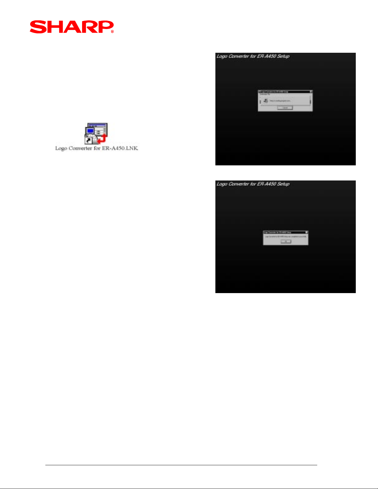
PC Setup for the Logo Converter Utility ..................................................................
Creating a Logo Image .............................................................................................
Sending the Image to the ER-A450T .......................................................................
Converting Images for the ER-02FD .......................................................................
Error Code Descriptions ...........................................................................................
Quick Start Procedures .............................................................................................
Contents
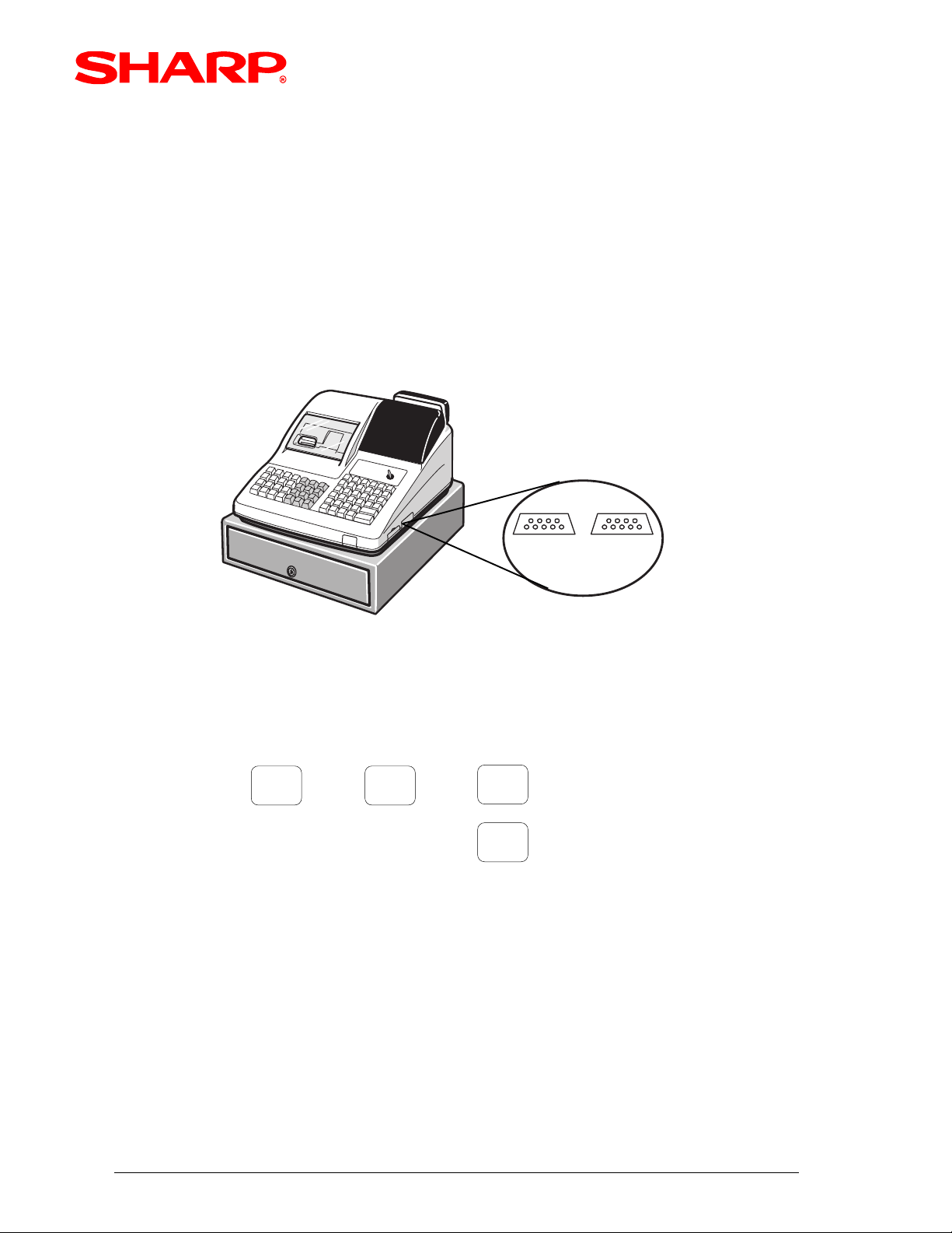
MODEL ER-A450T
I'm also here
to assist you !
Pg.
1
2
3
5
6
7
8
10
11
14
16
17
1.
2.
3.
4.
5.
6.
7.
8.
9.
Notice:
This software and/or documentation are furnished under license and may be used or copied in accordance with the terms
of such license.
Except as permitted by such license, no part of this software or documentation may be reproduced, stored in a retrieval
system, or transmitted, in any form or by any means, electronic, mechanical, recording, or otherwise, without the prior
written permission of Sharp Corporation.
Microsoft and Windows are either registered trademarks or trademarks of Microsoft Corporation in the United States and/
or other countries.
Designs and specifications are subject to change without notice.
Preliminary draft
LOGOCONV.exe Logo Converter Utility