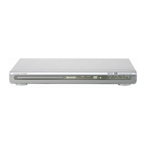
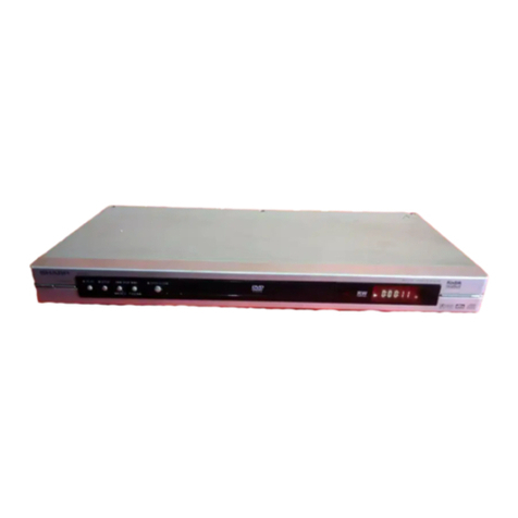
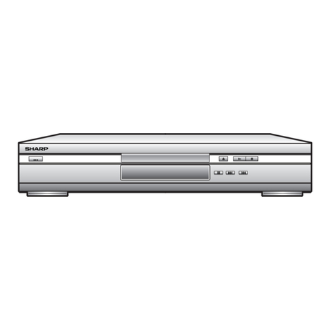
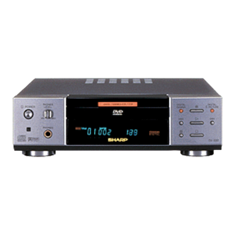
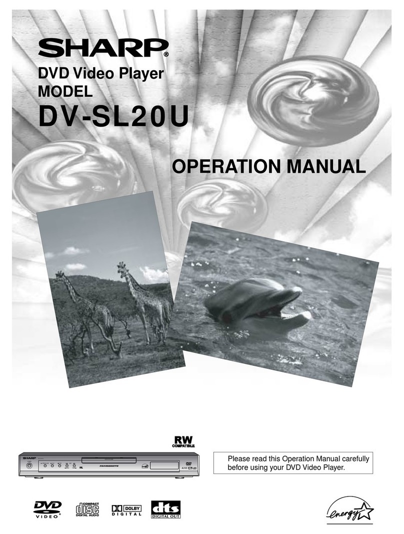
Sharp DV-SV 80 H User manual

1
SERVICE MANUAL
DV-SV 80 H
DV-SV 86 H
DV-SV 80S(G,S,Q,Y,R,RU,B)
DVD VIDEO PLAYER
DV-SV 80 H
DV-SV 86 H
DV-SV 80S(G,S,Q,Y,R,RU,B)
In the interests of user-safety (Required by safety regula-
tions in some countries) the set shpuld be restored to its
original condition and only parts identical to those specified
be used.
SHARP CORPORATION
CONTENTS
MODELS
9,'(2&'
',*,7$/9,'(2
1. IMPORTANT SAFEGUARDS AND PRECAUTIONS (DV-SV80) ............................... 2
2. SPECIFICATIONS ...................................................................................................... 3
3.GENERAL DESCRIPTION .......................................................................................... 4
3.1. MT1379 .................................................................................................................... 4
3.2. MEMORY ................................................................................................................
3.2.1. S DRAM MEMORY INTERFACE .........................................................................
3.3. DRIVE INTERFACES ..............................................................................................
3.4. FRONT PANEL ........................................................................................................
3. . REAR PANEL ...........................................................................................................
4. SYSTEM BLOCK DIAGRAM AND MT1379 PIN DESCRIPTION ................................ 6
4.1. MT1379 PIN DESCRIPTION .................................................................................... 6
4.2. SYSTEM BLOCK DIAGRAM .................................................................................... 8
. AUDIO OUTPUT ........................................................................................................ 9
6. AUDIO DACS ............................................................................................................. 9
7. VIDEO INTERFACE ................................................................................................... 9
7.1. VIDEO DISPLAY OUTPUT ....................................................................................... 9
8. FLASH MEMORY ..................................................................................................... 10
9. SERIAL EEPROM MEMORY ................................................................................... 10
10. AUDIO INTERFACE AUDIO SAMPLING RATE AND PLL
COMPONENT CONFIGURATION .............................................................................. 10
11. FRONT PANEL ....................................................................................................... 10
11.1. VFD CONTROLLER ............................................................................................. 10
12. CONNECTORS ....................................................................................................... 11
12.1. SCART CONNECTORS ....................................................................................... 11
12.2. CABLE DIAGRAM ................................................................................................ 12
13. CIRCUIT DESCRIPTION ....................................................................................... 13
13.1. POWER SUPPLY .................................................................................................. 13
13.2. FRONT PANEL .................................................................................................... 13
14. SOFWARE UPTATE ................................................................................................ 14
14.1. UNIVERSAL SERVICE PASSWORD FOR PARENTAL LEVEL = 1369 ................. 14
14.2. VERSION PAGE (HIDDEN MENU) ..................................................................... 14
14.3. BUILD NAMES FOR HARDWARE OPTIONS ..................................................... 14
14.4. REGION MANAGEMENT .................................................................................... 1
14. . CD UPTADE PROCEDURE ................................................................................ 1
14.6. TEST MODES ...................................................................................................... 17
1 . REPLACEMENT PART LIST ................................................................................... 17
16.CIRCUIT SCHEMATICS ......................................................................................... 18
16.1. MAIN BOARD ...................................................................................................... 18
16.2. POWER BOARD .................................................................................................. 2
16.3. SCART BOARD ................................................................................................... 26
16.4. FRONT PANNEL ................................................................................................. 27
S14M6DV-SV80H

2
1. IMPORTANT SAFEGUARDS AND PRECAUTIONS (DV-SV80)
CAUTION
BEFORE OPERATING YOUR NEW DVD PLAYER, PLEASE CAREFULLY READ THIS OPERATION MANUAL AND THEN SAVE
IT FOR FUTURE REFERENCE AS IT WILL BE USEFUL IF YOU HAVE ANY PROBLEMS OPERATING YOUR DVD PLAYER IN
THE FUTURE.
Note:
This unit c n be use only where the power supply
is AC 220V-240V, 50/60Hz. It c nnot be used
elsewhere.
CAUTION:
USE OF CONTROLS OR AD USTMENTS OR
PERFORMENCE OF PROCEDURES OTHER THAN
THOSE SPECIFIED HEREIN MAY RESULT IN
HAZARDOUS RADIATION EXPOSURE.
AS THE LASER BEAM USED IN THIS DVD PLAYER
IS HARMFUL TO EYES, DO NOT ATTEMPT TO
DISASSEMBLE THE CABINET. REFER SERVICING
TO QUALIFIED PERSONEL ONLY.
WARNING:
TO REDUCE THE RISK OF FIRE OR ELECTRIC
SHOCK, DO NOT EXPOSE THIS EQUIPMENT TO
RAIN OR MOISTURE.
TO REDUCE THE RISK OF FIRE OR ELECTRIC
SHOCK, AND ANNOYING INTERFERENCE, USE
THE RECOMMENDED ACCESSORIES ONLY.
This DVD pl yer is cl ssifield s CLASS 1 LASER
product.
The CLASS 1 LASER PRODUCT l bel is loc ted on the
re r cover.
This product c nt ins low power l ser device. To ensure
continued s fety do not remove ny cover or ttempt to g in
ccess to the inside of the product. Refer ll servicing to
qu lified personnel.
&/$ 66
/$6(5352'8&7
$8',2
)521 7
)521 7
9,'(2287 6&$57&2 11 (&72 5

3
2. SPECIFICATIONS
DVD/VIDEO CD/CD/CD-R/CD-RW/MP3/JPEG Pl yer
Power Requirements: 220 240 ~50 Hz Auto Adjust ble
Types of DiscsSupported: DVD: SS/SL 4.7 (DVD-5)
SS/DL 4.7 (DVD-9)
DS/SL 4.7 (DVD-10)
DS/DL 4.7 (DVD-18)
VCD
CD-DA
CD-R
CD-RW
MP-3
JPEG
Video Type MPEG-2 Video St nd rd Decoding (MPEG-1 supported)
Full-Screen Video Displ y of 720 x 576 (PAL) & 720 x 480 (NTSC)
pixels
50 nd 60 Hz fr me refresh r tes (PAL & NTSC)
Digit l bit-stre m processing r te up to 108Mbits/sec
Line resolution more th n 500 lines
Video Output An log Video:
(With using 6 x 10-bits / 27MHz video DACs)
CVBS: PAL / NTSC (Neg tive synchronised ), 1Vpp @ 75W (lo ded)
S-VIDEO: 1Vpp @ 75W (lo ded), c AT 0-286 Vpp (NTSC)
0-300Vpp (PAL) (lo ded)
or
Through 4-pin MiniDIN S-VIDEO connector
RGB + CVBS: Through Full Eurosc rt Output (Pin-8 Control)
Audio Type Dolby Digit l out nd Downmix
LPCM
DTS Digit l out
Audio Output Digit l Audio Outputs:
IEC 958
TOSLINK
An log Outputs:
24 Bit/ 96, 48, 44 1kHz down-s mpling DAC
2 RCA j ck outputs (Left / Right)
Left / Right udio outputs of Full Eurosc rt
Output / Ch nnel: 2 Vrms (0 dB fs, 1kHz)2.

4
3.GENERAL DESCRIPTION
3.1. MT1379
The MT1379 Progressive Sc n DVD-Pl yer Combo Chip is single-chip MPEG video decoding chip th t integr tes udio/video
stre m d t processing, TV encoder, four video DACs with M crovision. copy protection, DVD system n vig tion, system control
nd housekeeping functions.
The fe tures of this chip c n be listed s follows:
General Features:
Progressive sc n DVD-pl yer combo chip
Integr ted NTSC/PAL encoder.
Built-in progressive video output
DVD-Video, VCD 1.1, 2.0, nd SVCD
Unified tr ck buffer nd A/V decoding buffer.
Direct interf ce of 32-bit SDRAM.
Servo controller nd d t ch nnel processing.
Video Related Features:
M crovision 7.1 for NTSC/PAL interl ced video.
Simult neous composite video nd S-video outputs, or composite nd YUV outputs, or composite nd RGB outputs.
8-bit CCIR 601 YUV 4:2:2 output.
Decodes MPEG video nd MPEG2 m in profile t m in level.
M ximum input bit r te of 15Mbits/sec
Audio Related Features:
Dolby Digit l (AC-3) nd Dolby Pro Logic
Dolby Digit l S/PDIF digit l udio output
High-Definition Comp tible Digit l. (HDCD) decoding
Dolby Digit l Cl ss A nd HDCD certified
SRS TrueSurround
CD-DA
MP3

5
3.2. MEMORY
3.2.1. S DRAM MEMORY INTERFACE
The MT1379 provides glueless 16-bit interf ce to DRAM memory devices used s OSD, MPEG stre m nd video buffer
memory for DVD pl yer. The m ximum mount of memory supported is 16 MB of Synchronous DRAM (SDRAM). The memory
interf ce is configur ble in depth to support 128-Mb ddressing. The memory interf ce controls ccess to both extern l SDRAM
memories, which c n be the sole unified extern l re d/write memory cting s progr m nd d t memory s well s v rious
decoding nd displ y buffers.
3.3. DRIVE INTERFACES
The MT1379 supports the DV34 interf ce, nd other RF nd servo interf ces used by m ny types of DVD lo ders. These
interf ces meet the specific tions of m ny DVD lo der m nuf cturers.
3.4. FRONT PANEL
The front p nel is b sed round n Fut b VFD nd common NEC front p nel controller chip, (uPD16311). The MT1379
controls the uPD16311 using sever l control sign ls, (clock, d t , chip select). The infr red remote control sign l is p ssed
directly to the MT1379 for decoding.
3. . REAR PANEL
A typic l re r p nel is included in the reference design. This re r p nel supports:
Six ch nnel or two ch nnel udio outputs
Optic l nd co x S/PDIF outputs.
Composite, S-Video, nd SCART outputs
The six-video sign ls used to provide CVBS, S-Video, nd RGB re gener ted by the MT1379s intern l video DAC. The video
sign ls re buffered by extern l circuitry.
Six ch nnel udio output by the MT1379 in the form of three I2S (or simil r) d t stre ms. The S/PDIF seri l stre m is lso
gener ted by the MT1379 output by the re r p nel. The six ch nnel udio DACs (AK4356,PCM1606) re used for six ch nnel
udio output with MT1379, nd simil rly AK4382A ,CS4392 Audio DACs re used for two ch nnel udio output with MT1379.

6
4. SYSTEM BLOCK DIAGRAM AND MT1379 PIN DESCRIPTION
4.1. MT1379 PIN DESCRIPTION
6<0%2/ 7<3( 3,1180%(56 '(),1,7,21
'966 *URXQG *URXQGSLQIRULQWHUQDOGLJLWDOFLUFXLWU\
XUUHQWUHIHUHQFHLQSXW,WJHQHUDWHVUHIHUHQFH
,5() $QDORJ,QSXW XUUHQWIRUGDWD3// RQQHFWDQH[WHUQDO.
5HVLVWRUWRWKLVSLQDQG3//966
3//966 *URXQG *URXQGSLQIRU3//DQGDQDORJFLUFXLWU\
/3,23 $QDORJ2XWSXW 3RVLWLYHRXWSXWIRUORZSDVVILOWHU/)3
/3,21 $QDORJ2XWSXW 1HJDWLYHRXWSXWIRU/)3
/3)21 $QDORJ2XWSXW 1HJDWLYHRXWSXWRIORRSILOWHUDPSOLILHU/)$
/3),3 $QDORJ,QSXW 3RVLWLYHLQSXWRI/)$
/3),1 $QDORJ,QSXW 1HJDWLYHLQSXWRI/)$
/3)23 $QDORJ2XWSXW 3RVLWLYHRXWSXWRI/)$
-,7)2 $QDORJ2XWSXW 5)MLWWHUPHWHURXWSXW
-,7)1 $QDORJ,QSXW 1HJDWLYHLQSXWRIWKHRSHUDWLRQDODPSOLILHUIRU5)MLJJHUPHWHU
3//9'' 3RZHU 9SRZHUSLQIRUGDWD3//DQGUHODWHGDQDORJFLUFXLWU\
)22 $QDORJ2XWSXW )RFXVVHUYRRXWSXW3'0RXWSXWRIIRFXVVHUYRFRPSHQVDWRU
752 $QDORJ2XWSXW 7UDFNLQJVHUYRRXWSXW3'0RXWSXWRIWUDFNLQJVHUYRFRPSHQVDWRU
7UD\RSHQRXWSXWFRQWUROOHGE\PLFURFRQWUROOHU7KLVLV3:0RXWSXW
7523(13:0 $QDORJ2XWSXW IRU75:0(1K5: RULVGLJLWDORXWSXWIRU75:0(1K5:
3:0287 $QDORJ2XWSXW VWDQGQGJHQHUDO3:0RXWSXW
'9'' 3RZHU 9SRZHUSLQIRULQWHUQDOO\IXOO\GLJLWDOFLUFXLWU\
'02 $QDORJ2XWSXW 'LVNPRWRUFRQWURORXWSXW3:0RXWSXW
)02 $QDORJ2XWSXW )HHGPRWRUFRQWURO3:0RXWSXW
)* ,QSXW 0RWRU+DOOVHQVRULQSXW
+,*+$ ,QRXWa0$65
38 0LFURFRQWUROOHUDGGUHVV
+,*+$ ,QRXWa0$65
38 0LFURFRQWUROOHUDGGUHVV
$' ,QRXWa0$65 0LFURFRQWUROOHUDGGUHVVGDWD
'9'' 3RZHU
SRZHUSLQIRULQWHUQDOGLJLWDOFLUFXLWU\
$' ,QRXWa0$65 0LFURFRQWUROOHUDGGUHVVGDWD
,2$ ,QRXWa0$65
38 0LFURFRQWUROOHUDGUHVV,2
,2$ ,QRXWa0$65
38 0LFURFRQWUROOHUDGUHVV,2
$ 2XWSXWa0$65 )ODVKDGUHVV
,2$ ,QRXWa0$65
607 )ODVKDGUHVV
$3//966 *URXQG *URXQGSLQIRUDXGLRFORFNFLUFXLWU\
$3//9'' 3RZHU 9SRZHUSLQIRUDXGLRFORFNFLUFXLWU\
$/( ,QRXW
a0$65386
07
0LFURFRQWUROOHUDGGUHVVODWFKHQDEOH
,22( ,QRXWa0$65
607 )ODVKRXWSXWHQDEOHDFWLYHORZ,2
,2:5 ,QRXW
a0$65607 )ODVKZULWHHQDEOHDFWLYHORZ,2
,2 6 ,QRXW
a0$65386
07
)ODVKFKLSVHOHFWDFWLYHORZ,2
83B ,QRXW
0$6538607 0LFURFRQWUROOHUSRUW«
83B ,QRXW
0$6538607 0LFURFRQWUROOHUSRUW
,17 ,QRXW
a0$65386
07
0LFURFRQWUROOHULQWHUUXSWDFWLYHORZ
,5 ,QSXW607 ,5FRQWUROVLJQDOLQSXW
83B ,QRXW 0LFURFRQWUROOHUSRUW
8:5 ,QRXW
a0$65386
07
0LFURFRQWUROOHUZULWHVWUREHDFWLYHORZ
85' ,QRXW
a0$65386
07
0LFURFRQWUROOHUZULWHVWUREHDFWLYHORZ

7
6<0%2/ 7<3( 3,1180%(56 '(),1,7,21
5' '5$0GDWD '5$0GDWD
5:( 2XWSXWa0$65 '5$0ZULWHHQD OHDFWLYHORZ
&$6 2XWSXWa0$65 '5$0FROXPQDGUHVVVWUR HDFWLYHORZ
5$6 2XWSXWa0$65 '5$0URZDGUHVVVWUR HDFWLYHORZ
5&6 2XWSXWa0$65 '5$0FKLSVHOHFWDFWLYHORZ
%$ 2XWSXWa0$65 '5$0 DQNDGUHVV
5' ,QRXW
a0$65383'
607
'5$0GDWD
&/. 2XWSXWa0$65 '5$0FORFN
&/( 2XWSXWa0$65 '5$0FORFNHQD OH
5$ 2XWSXWa0$65 '5$0DGUHVV LWRUVHULDOGDWDFKDQQHO
5$
2XWSXWa0$65
'5$0DGUHVVHV
'09'' 3RZHU 93RZHUSLQIRU'5$0FORFNFLUFXLWU\
'0966 *URXQG *URXQGSLQIRU'5$0FORFNFLUFXLWU\
'40 2XWSXWa0$65 0DVNIRU'5$0LQSXWRXWSXW \WH
%$ 2XWSXWa0$65 '5$0 DQNDGGUHVV
5' ,QRXWa0$65
383'607 '5$0FRUUHVSRQGLQJGDWD
5' ,QRXWa0$65
383'607 '5$0GDWD9LGHRLQ'DWD3RUW$
5' ,QRXWa0$65
383'607 '5$0GDWD9LGHRLQ'DWD3RUW$
$%&. 2XWSXW0$ $XGLR LWFORFN
$/5&. ,QRXW0$3'607 $XGLR/5FKDQQHOFORFN7UDSYDOXHLQSRZHURQUHVHWH[WLQW
$&/. ,QRXW0$ $XGLR'$&PDVWHUFORFNDXGLRVDPSOHIUHTXHQF\
0&B'$7$ ,QSXW 0LFURSKRQHVHULDOLQSXW
63',) 2XWSXWa0$65
212)) 63',)RXWSXW
$6'$7$ ,QRXW0$3'607 $XGLRVHULDOGDWD/57UDSYDOXHLQSRZHURQUHVHWIDFWRU\WHVW
PRGHQRUPDOPRGH
$6'$7$ ,QRXW0$3'607 $XGLRVHULDOGDWDVXUURXQG/57UDSYDOXHLQSRZHURQUHVHW
$6'$7$ ,QRXW0$3'607 $XGLRVHULDOGDWDFHQWHUOHIW7UDSYDOXHLQSRZHURQUHVHW
$6'$7$ ,QRXW0$3'607 $XGLRVHULDOGDWDVXUURXQG/57UDSYDOXHLQSRZHURQUHVHWYLGHRLQ
GDWDSRUW
$6'$7$ ,QRXW0$3'607 $XGLRVHULDOGDWDFHQWHUOHIW7UDSYDOXHLQSRZHURQUHVHWYLGHRLQ
GDWDSRUW
'$&9''& 3RZHU 9SRZHUSLQIRU9ø'(2'$&FLUFXLWU\
95() $QDORJLQSXW %DQGJDSUHIHUQFHYROWDJH
)6 $QDORJ2XWSXW )XOOVFDOHDGMXVWPHQW
<89&,1 2XWSXW0$65 9LGHRGDWDRXWSXW LW&RPSHQVDWLRQFDSDFLWRU
'$&966& *URXQG *URXQGSLQIRU9,'(2'$&FLUFXLWU\
<89& 2XWSXW0$65 9LGHRGDWDRXWSXW LW&RPSHQVDWLRQFDSDFLWRU
'$&9''% 3RZHU 9SRZHUSLQIRU9ø'(2'$&FLUFXLWU\
<89< 2XWSXW0$65 9LGHRGDWDRXWSXW LW$QDORJ<RXWSXW
'$&966% *URXQG *URXQGSLQIRU9,'(2'$&FLUFXLWU\
<89&9%6 2XWSXW0$65 9LGHRGDWDRXWSXW LW$QDORJFRPSRVLWHRXWSXW
'$&9''$ 3RZHU 9SRZHUSLQIRU9ø'(2'$&FLUFXLWU\
<89* 2XWSXW0$65 9LGHRGDWDRXWSXW LW*UHHQRU<
'$&966$ *URXQG *URXQGSLQIRU9,'(2'$&FLUFXLWU\
<89% 2XWSXW0$65 9LGHRGDWDRXWSXW LW%OXHRU&%
<895 2XWSXW0$65 9LGHRGDWDRXWSXW LW5HGRU&5
,&( ,QSXW3'607 0LFURFRQWUROOHU,&(PRGHHQD OH

8
4.2. SYSTEM BLOCK DIAGRAM
A s mple system block di gr m for the MT1379 DVD pl yer bo rd design is shown in the
following figure:

9
. AUDIO OUTPUT
The MT1379 supports two-ch nnel nd six-ch nnel n log udio output. In system configur tion with six n log outputs,
the front left nd right ch nnels c n be configured to provide the stereo (2 ch nnel) outputs nd Dolby Surround, or the left nd
right front ch nnels for 5.1 ch nnel surround system.
The MT1379 lso provides digit l output in S/PDIF form t. The bo rd supports both optic l nd co xi l SPDIF outputs.
6. AUDIO DACS
The MT1379 supports sever l v ri tions of n I2S type bus, v rying the order of the d t bits (le ding or no le ding zero bit,
left or right lignment within fr me, nd MSB or LSB first) is possible using the MT1379 intern l configur tion registers. The
I2S form t uses four stereo d t lines nd three clock lines. The I2S d t nd clock lines c n be connected directly to one or
more udio DAC to gener te n log udio output.
The two-ch nnel DAC is n AKM AK4382A. The DACs support up to 192kHz s mpling r te.
The outputs of the DACs re differenti l, not single ended so buffering circuit is required. The buffer circuits use N tion l
LM833 op- mps to perform the low-p ss filtering nd the buffering.
7. VIDEO INTERFACE
7.1. VIDEO DISPLAY OUTPUT
The video output section controls the tr nsfer of video fr mes stored in memory to the intern l TV encoder of the MT1379. The
output section consists of progr mm ble CRT controller c p ble of oper ting either in M ster or Sl ve mode.
The video output section fe tures intern l line buffers which llow the outgoing lumin nce nd chromin nce d t to m tch
the intern l clock r tes with extern l pixel clock r tes, e sily f cilit ting YUV4: 2:2 to YUV4: 2:0 component nd s mple
conversion. A polyph se filter chieves rbitr ry horizont l decim tion nd interpol tion.
Video Bus
The video bus h s 8 YUV d t pins th t tr nsfer lumin nce nd chromin nce (YUV) pixels in CCIR601 pixel form t (4:2:2).
In this form t, there re h lf s m ny chromin nce (U or V) pixels per line s lumin nce (Y) pixels; there re s m ny
chromin nce lines s lumin nce.
Video Post-Processing
The MT1379 video post-processing circuitry provides support for the color conversion, sc ling, nd filtering functions through
combin tion of speci l h rdw re nd softw re. Horizont l up-s mpling nd filtering is done with progr mm ble, 7-t p
polyph se filter b nk for ccur te
non-integer interpol tions. Vertic l sc ling is chieved by repe ting nd dropping lines in ccord nce with the pplic ble
sc ling r tio.
Video Timing
The video bus c n be clocked either by double pixel clock nd clock qu lifier or by single pixel clock. The double clock typic lly
is used for TV displ ys, the single for computer displ ys.

10
8. FLASH MEMORY
The decoder bo rd supports 70ns Fl sh memories. Currently 4 configur tions re supported:
FLASH_512K_8b
FLASH_1024K_8b
FLASH_512Kx2_8b
FLASH_512Kx2_16b
The MT1379 permits both 8- nd 16-bit common memory I/O ccesses with remov ble stor ge c rd vi the host interf ce.
9. SERIAL EEPROM MEMORY
An I2C seri l EEPROM is used to store user configur tion (i.e. l ngu ge preferences, spe ker setup, etc.) nd softw re
configur tion.. Industry st nd rd EEPROM r nge in size from 1kbit to 256kbit nd sh re the s me IC footprint nd pinout. The
def ult device is 2kbit, 256kx 8, SOIC8 SGS Thomson ST24C02M1 or equiv lent.
10. AUDIO INTERFACE AUDIO SAMPLING RATE AND PLL COMPONENT CONFIGURATION
The MT1379 udio mode configur tion is select ble, llowing it to interf ce directly with low-cost udio DACs nd ADCs. The
udio port provides st nd rd I2S interf ce input nd output nd S/PDIF (IEC958) udio output. Stereo mode is in I2S form t
while six ch nnels Dolby Digit l (5.1 ch nnel) udio output c n be ch nneled through the S/PDIF. The S/PDIF interf ce consists
of bi-ph se m rk encoder, which h s low skew. The tr nsmit I2S interf ce supports the 112, 128, 192, 256, 384, nd 512
s mpling frequency form ts, where s mpling frequency Fs is usu lly 32 kHz, 44.1 kHz, 48 kHz, 96 kHz, or 192 kHz. The udio
s mples for the I2S tr nsmit interf ce c n be 16, 18, 20, 24, nd 32-bit s mples.
For Line r PCM udio stre m form t, the MT1379 supports 48 kHz nd 96 kHz. Dolby Digit l udio only supports 48 kHz. The
MT1379 incorpor tes built-in progr mm ble n log PLL in the device rchitecture in order to gener te m ster udio clock.
The MCLK pin is for the udio DAC clock nd c n either be n output from or n input to the MT1379. Audio d t out (TSD) nd
udio fr me sync (TWS) re clocked out of the MT1379 b sed on the udio tr nsmit bit clock (TBCK). Audio receive bit clock
(RBCK) is used to clock in udio d t in (RSD) nd udio receive fr me sync (RWS).
11. FRONT PANEL
11.1. VFD CONTROLLER
The VFD controller is NEC uPD16311. This controller is not processor, but does include simple st te m chine which
sc ns the VFD nd re ds the front p nel button m trix. The 16311 lso includes RAM so it c n store the current st te of ll
the VFD icons nd segments. Therefore, the 16311 need only be ccessed when the VFD st tus ch nges nd when the button
st tus is re d. The MT1379 c n control this chip directly using PIO pins or c n llow the front p nel PIC to control the VFD.

11
12. CONNECTORS
12.1. SCART CONNECTORS
Pinout of the sc rt connector:
1 à Audio Right Out
2 à Audio Right In
3 à Audio Left / Monu Out
4 à Audio Gnd
5 à Blue Gnd
6 à Audio Left / Mono In
7 à Blue
8 à Control Volt ge
9 à Green Gnd
10 à Comms D t 2
11 à Green
12 à Comms D t 1
13 à Red Gnd
14 à Comms D t Gnd
15 à Red
16 à F st Bl nking
17 à Video Gnd
18 à F st Bl nking Gnd
19 à Composite Video In
20 à Composite Video Out
21 à Shield
Some che per SCART c bles use unshielded wires, which is just bout ccept ble for short c ble lengths. For longer lengths,
shielded co- x c ble become essenti l.
Scart Signals:
Audio signals
0.5V RMS, <1K output imped nce, >10K input imped nce.
Red, Green, Blue
0.7Vpp ±2dB, 75R input nd output imped nce. Note th t the Red connection (pin 20) c n ltern tively c rry the S-Video
Chromin nce sign l, which is 0.3V.
Composite Video / CSync
1Vpp including sync, ±2dB, 75R input nd output imped nce.B ndwidth = 25Hz to 4.8MHz for norm l TV Video de-emph sis
to CCIR 405.1 (625-line TV)

12
Fast Blanking
75R input nd output imped nce. This control volt ge llows devices to over-ride the composite video input with RGB inputs,
for ex mple when inserting closed c ption text. It is c lled f st bec use this c n be done t the s me speeds s other video
sign ls, which is why it requires the s me 75R imped nces.
0 to 0.4V: TV is driven by the composite video input sign l (pin 19). Left unconnected, it is pulled to 0V by its 75R
termin tion.
1V to 3V: the TV is driven by the sign ls Red, Green, Blue nd composite sync. The l tter is sent to the TV on pin 19.
This sign l is useful when using TV to displ y the RGB output of devices such s home computers with TV-
comp tible fr me r tes. Tying the sign l to 5V vi 100R forms potenti l divider with the 75R termin tion,
holding the sign l t round 2V. Altern tively, if TTL level (0 to 5V) neg tive sync pulse is v il ble, this will
be high during the displ y periods, so this c n drive the bl nking sign l vi suit ble resistor.
Control Voltage
0 to 2V = TV, Norm l.
5 to 8V = TV wide screen
9.5 to 12V = AV mode
12.2. CABLE DIAGRAM
$
'
(
)
*
3/
3/
6&$57
%2$5'
/2$'(5
238
&DEOH
0RWRU
&DEOH
-
-
- - 3/
3/
)52173$1(/
32:(5
0$ 1%2$5'
,7(0 3$5712 '(6&5,37,21 &2'(
$-% &1$63:&)(5'9'
'-% &1$636,6:&%57)(58/ $:*
(-% &1$63:)(5
)-% &1$636,6:&%578/ $:*
*-% 32:(5&25'$66<0:)7=6$7(//,7(

13
13. CIRCUIT DESCRIPTION
13.1. POWER SUPPLY
Socket PL1 is the 220VAC input.
2.5A fuse F1 is used to protect the device g inst short circuit.
Line filters nd c p citors L1, C1, L5 nd L6 re used to block the p r sitic coming from the m ins. They lso prevent the
noise, produced in the circuit, from being injected to the line.
Volt ge is rectified by using diodes D1, D2, D3 nd D4. Using c p citor C3 (470mf) DC volt ge is produced. (310- 320VDC).
The current in the prim ry side of the tr nsformer TR3 comes to the SMPS IC (IC3 TOP223Y). The SMPS IC h s three-pin
TO-220 c se nd cooler is mounted on it. It h s built-in oscill tor, overcurrent nd overvolt ge protection circuitry nd runs
t 100kHz. It st rts with the current from the prim ry side of the tr nsformer nd follows the current from the feedb ck winding.
Volt ges on the second ry side re s follows: -22V, -12V, 3.3V, 5V, 15V.
D14 TL431 is const nt current regul tor. TL431 w tches the 5 volts nd supplies the required current to IC2. There re
LED nd photo tr nsistor in IC2. The LED inside the IC2 tr nsmits the v lue of the current from D14 to phototr nsistor.
Depending on the current g in of the phototr nsistor IC3 keeps the volt ge on the 5-volt-winding const nt.
Adjust ble volt ge regul tor IC5 (LM317) supplies 12 Volts.
When the device enters st nd-by mode, tr nsistor Q2 st rts to conduct nd pulls the djust pin of IC5 to ground, where this
cuts 12Volts off.
22 Volts is used to feed the VFD (V cuum Fluorescent Displ y) driver IC on the front p nel.
Tr nsistor Q4 nd zener diode D14 re used to regul te +12 Volts. This volt ge is used to feed op- mps on the b ck p nel.
13.2. FRONT PANEL
All the functions on the front p nel re controlled by U7 (MT1379) on the m inbo rd.
U7 sends the comm nds to IC2 uPD16311 vi socket PL1 (pins 3,4 nd 5).
There re 16 keys sc nning function, 2 LED outputs, 1 St nd-by output nd VFD drivers on IC2.
Pin 52 is the oscill tor pin nd is connected vi R5 56K.
LED D6 is red in st nd-by mode nd green when the device is on. When entering st nd-by mode, pin 48 goes HIGH (+5V)
nd controls the tr nsistor Q2 on the power bo rd.
V cuum fluorescent displ y MD2 is speci lly designed for DVD.
The sc nned keys re tr nsmitted vi IC2 pin 5 nd 6 to U1 on the m inbo rd.
IR remote control receiver module IC3 (TSOP1836) sends the comm nds from the remote control directly to U1.
Socket PL2 c rries the VFD fil ment volt ge nd 22 Volts.
13.3 BACK PANEL
There re 1 SCART connector (PL4), 2 pieces RCA udio j cks, for udio output, 1 co xi l digit l udio output JK3 nd 1 l ser
digit l udio output PL5 on the b ck p nel.
TOTX176 is used for l ser output.
For co xi l udio output SPDIF is used.
Q22 .. Q27 tr nsistors re to mute the udio outputs while switching the st te of the unit(power on/off)
There re two op- mps in U14, U16 nd U18. They re used for left,right,re r left nd right, subwoofer center udio ch nnels.
The feedb ck resistor is mplifying the g in.
SCART pin 8 controls 16:9 nd 4:3 mode using Q28,Q29 nd Q30.
When the pin8 output of the sc rt becomes 5 Volts, 4:3 mode is selected nd 16:9 mode is selected when this output becomes
0. The circuit is djusted to output 12 Volts for 4:3 mode nd 6 Volts for 16:9 mode.
Tr nsistors Q28,Q29 nd Q30 tr nsmit these volt ges when the device is turned on nd cuts them off when it is turned off.
FBL on pin 16 tr nsmits 5 Volts vi tr nsistors Q12 nd Q14 when the device is on.

14
Socket PL2, which is coming from the m inbo rd, tr nsmits RED, GREEN, BLUE nd VIDEO sign ls to SCART over the buffer
st ge.
LUMA nd CHROMA sign ls of S-Video re tr nsmitted to S-Video socket vi tr nsistors Q11 nd Q13 respectively.
14. SOFWARE UPTATE
14.1. UNIVERSAL SERVICE PASSWORD FOR PARENTAL LEVEL = 1369
14.2. VERSION PAGE (HIDDEN MENU)
To see Version P ge;
- Press DISPLAY button from remote
- Press 1-3-5-7 t Setup Menu
- Setup Menu screen refresh nd Version selection c n be seen under Preferences Setup
- Select Version for Version P ge
- First 6 lines cont ins current VERSION inform tion.
- 5th line is for customers
Other lines (Sub-Ver, 8032, Servo, Risc) for f ctory use only;
5th line cont ins build inform tion ex mple: EF82p
5th line cont ins h rdw re option ex mple: C2FN1.bin
- Press DISPLAY button on remote control to exit hidden menu.
5th line lso shows CD upd te file n me. It defines lso H rdw re options.
14.3. BUILD NAMES FOR HARDWARE OPTIONS
Option List:
1. OPU Option
2. VFD Option
3. DAC Option
4. L ngu ge Group
There is n ming st nd rd for softw re builds ccording to pl yers h rdw re options like;
VFD Type: N = New sm ll VFD
OPU Type: F = FUSS HITACHI HOP 1200
DAC Type: C2 = CS4392
Ex mple:
C2FN2.bin = CS4392, FUSS, NEW sm ll VFD, L ngu ge Group 2
Note: Upd te CD should h ve no volume ID.

15
14.4. REGION MANAGEMENT
At version P ge by using rrow keys you c n ch nge region.
14. . CD UPTADE PROCEDURE
1) Pl yer c n be upd ted utom tic lly with Upd te CD which cont ins proper file. Check hidden menu for upd te file n me.
2) Burn up CD* within proper upd te file
3) There should be no Volume N me for CD
Open Tr y nd pl ce upd te CD
4) You c n see Upgr de File Detected. Press Pl y to st rt OSD mess ge
5) Press Pl y button to st rt upgr de
6) You c n see File copying OSD mess ge for few second
7) Tr y is open utom tic lly
8) No need for CD in tr y; T ke it from tr y.
9) During upgr de procedure CD upgr de st rt, Ple se w it.. indic tor t OSD, nd UPG indic tor t VFD
10) Upgr de procedure t kes bout few minutes, ple se w it if tr y is open.
11) When CD upd te is finished tr y is closed, screen is refreshed, upd te is finished.
NOTE: * For NERO Burning Rom program
ide l configur tion;
Multisession selection should be No Multisession
File form t should be ISO9660 .Do not use Joliet
It is better to er se with Quick Er se if you use CD-RW before burning.
There should be no Volume l ble.
It m y be better to put some dummy files in Cd with upd te file.

16

17
14.6. TEST MODES
A. VFD Full Segment Test Mode
During pressing stop button on front p nel if you press St ndby button ll segments of VFD re highlighted.
B. Factory Test Short Cuts
At No Disc if you press, from Remote control:
C C 1 : S Video Set
C C 2 : RGB Set
C C 3 : 6ch off (For 6ch Models)
C C 4 :6ch on (For 6ch Models)
C C 5 :All Video Out En ble nd 6ch on
Note:
These short cuts for f ctory use only. If you use these short cuts for testing video outs. You should select RESET t
PREFERENCE PAGE in SETUP MENU.
To see Version P ge;
- Press DISPLAY button from remote
- Press 1-3-5-7 t Setup Menu
- Setup Menu screen refresh nd Version selection c n be seen under Preferences Setup
- Select Version for Version P ge
- First 6 lines cont ins current VERSION inform tion.
- 5th line is for customers
Other lines (Sub-Ver, 8032, Servo, Risc) for f ctory use only;
5th line cont ins build inform tion ex mple: EF82p
5th line cont ins h rdw re option ex mple: C2FN1.bin
- Press DISPLAY button on remote control to exit hidden menu.
5th line lso shows CD upd te file n me. It defines lso H rdw re options.
1 . REPLACEMENT PART LIST
,7(0 3$5712 '(6&5,37,21 &2'(
'9'0DLQERDUG -% 0$,16/,0)8660$1 &+:2(0&I
3RZHUERDUG -% 32:(5%'9'6$1.(10$1 :2(0&
'LVSOD\ERDUGLQFOXGHGZLUHKDUQHVV -% )52173'9'0$1 :2(0&
6&$57WHUPLQDOERDUG -% 6&$57$66<0$1 :2(0&
/RDGHUXQLW -% '9'/2$'(5/1+$%
)URQW3DQHOLQFOXGHGEXWWRQVDQGSDQHOV -% )5217$06/9%/8( $'7
7RSFDELQHW -% 723&29(506,/9(55 $'7
%RWWRPFDELQHW -% %27720&29(55
5HDU3DQHOLQFOXGHG3RZHUFRUG -% %$&.&29(5)8//&+$'7
2SHUDWLRQ0DQXDO -% .8/.%/$&.',$021'%''9'(1*507.$'7
5HPRWH&RQWUROXQLW -% 5&'9'8.6,/9(5$'7
&DUWRQ -% .$57.8%/$&.',$021'%''9'(1*5$'7

18
16.CIRCUIT SCHEMATICS
16.1. MAIN BOARD
12MB10F3 DV-SV80H SHEET 1/7

19
12MB10F3 DV-SV80H SHEET 2/7
20
12MB10F3 DV-SV80H SHEET 3/7
Other manuals for DV-SV 80 H
3
This manual suits for next models
8
Table of contents
Other Sharp DVD Player manuals

Sharp
Sharp DV-SV97H User manual

Sharp
Sharp DV-S1S(S) User manual

Sharp
Sharp DV-SV80S(G) User manual

Sharp
Sharp CD-DV600W User manual

Sharp
Sharp DV-600S User manual

Sharp
Sharp DV-SL700W User manual

Sharp
Sharp DV-SL10 User manual

Sharp
Sharp DV-SL1200W User manual

Sharp
Sharp DV-720H User manual

Sharp
Sharp DV-S11S(G) User manual

Sharp
Sharp DV-SV80S User manual

Sharp
Sharp DV-SL1000W User manual

Sharp
Sharp DV-SL800W User manual

Sharp
Sharp DV-SV 80 H User manual

Sharp
Sharp DV-SL10S(G) User manual

Sharp
Sharp DV-740H User manual

Sharp
Sharp DV-SL80X User manual

Sharp
Sharp DV-720X User manual

Sharp
Sharp DV-SV80S(S) User manual

Sharp
Sharp DV-AT4000 User manual