Sharp DV-SL10S User manual

1
DV-SL10S(G)/DV-SL10W/DV-SL10/DV-SL10X/DV-SL10S(Q)/DV-SL10S(S)/DV-SL10(RU)
S63C5DV-SL10S
SERVICE MANUAL
MODELS
DV-SL10S(G)
DV-SL10W
DV-SL10
DV-SL10X
DV-SL10S(Q)
DV-SL10S(S)
DV-SL10(RU)
SERVICE MANUAL DVD VIDEO PLAYER MODELS DV-SL10S(G)/DV-SL10W/DV-SL10/DV-SL10X/DV-SL10S(Q)/DV-SL10S(S)/DV-SL10(RU)
This document has been published to be used for
after sales service only.
The contents are subject to change without notice.
SHARP CORPORATION
DVD VIDEO PLAYER
Page
OPERATING CONTROLS AND FUNCTIONS .................................................................................. 1-1-1
BLOCK DIAGRAMS........................................................................................................................... 1-2-1
SCHEMATIC DIAGRAMS/ CBA’S AND TEST POINTS .................................................................... 1-3-1
WAVEFORMS.................................................................................................................................... 1-4-1
WIRING DIAGRAM ............................................................................................................................ 1-5-1
LEAD IDENTIFICATIONS.................................................................................................................. 1-6-1
EXPLODED VIEWS ........................................................................................................................... 1-7-1
DIFFERENT PARTS FROM ORIGINAL MODEL (DV-SL10H).......................................................... 1-8-1
CONTENTS
In the interests of user-safety (Required by safety regula-
tions in some countries) the set should be restored to its
original condition and only parts identical to those specified
be used.
This service manual supplement (DV-SL10S(G)/DV-SL10W/DV-
SL10/DV-SL10X/DV-SL10S(Q)/DV-SL10S(S)/DV-SL10(RU))
contains only the difference from the original model.
For all other data, see each original service manual for
DV-SL10H/DV-SL10S(Y)/DV-SL10S(R).

1-1-1 E5753IB
OPERATING CONTROLS AND FUNCTIONS
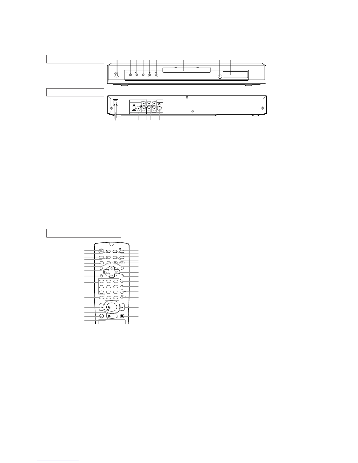
[ DV-SL10S(G)/DV-SL10S(Q) ]
REAR VIEW
!"
FRONT PANEL
REMOTE CONTROL
#$
$
%
$
$
%
!"
$$
$$
&
1. OPERATE
'( )*+',- '-. /012.3 '( (3 !!
2. OPEN/CLOSE
'( (/.4,0(). '-. 5+), '312
3. PLAY
'( )'13' (3 3.)67. 5+), /01281,9
4. STOP
'( )'(/ /01281,9
5. SKIP
H
/ REV
h
:(.) '( /3.;+(6) ,-1/'.3 (3 '31,9 563+4: /01281,9< /3.))
145 -(05 =(3 > ).,(45) =(3 1 3.;.3). ).13,-
6. SKIP
G
/ FWD
g
:(.) '( 4.?' ,-1/'.3 (3 '31,9 563+4: /01281,9< /3.)) 145
-(05 =(3 > ).,(45) =(3 1 =(3*135 ).13,-
7. Disc ray
8. Remo e sensor window
9. Display
10. MAIN (AC Power Cord)
,(44.,' '( 1 )'145135 (6'0.'
11. AUDIO OUT (Lef /Righ )
,(44.,' '( +4/6') (= 14 17/0+=+.3@ 3.,.+;.3 (3
)'.3.( )2)'.7
12. DIGITAL (Digi al audio ou )
,(44.,' '( +4/6') (= 1 5+:+'10 ,(1?+10 165+(
.A6+/7.4'
13. VIDEO OUT
,(44.,' '( '-. +5.( 4/6' (= 1
14. S-VIDEO OUT
,(44.,' '( 1 *+'- +5.( +4/6')
15. AV (TV)
,(44.,' ,180. '( 1
Cau ion: Do no ouch he inner pins of he jacks on he
rear panel. Elec ros a ic discharge may cause permanen
damage o he player.
10. CLEAR Bu on
.).') 1 ).''+4:>
11. REV Bu on
!1)' 3.;.3). /01281,9 '( 1 5.)+3.5 /(+4'>
12. PLAY Bu on
'13') /01281,9 (= '-. 5+), ,(4'.4')>
13. DIRECT SKIP Bu on
3.)) '( 0(,1'. 1 5.)+3.5 /(+4'>
14. STOP Bu on
'(/) (/.31'+(4 (= '-. 5+),>
15. OPEN/CLOSE Bu on
3.)) '( +4).3' 5+),) +4'( (3 3.7(;. '-.7 =3(7 '-. '312>
16. SETUP Bu on
3.)) '( .4'.3 '-. ).'6/ 7(5. (3 '( ,-14:. ).'6/ +'.7)>
17. MARKER Bu on
3.)) '( ,100 81,9 '-. $139.3 5+)/012>
18. MODE Bu on
,'+;1'.) /3(:3177. /01281,9 (3 3145(7 /01281,9
7(5.>$ ,'+;1'.) '-. )(645>
19. AUDIO Bu on
3.)) '( ).0.,' 1 5.)+3.5 165+( 014:61:. (3 )(645 7(5.>
20. ANGLE Bu on
3.)) '( ,-14:. '-. ,17.31 14:0. '( ).. '-. ).A6.4,. 8.+4:
/012.5 81,9 =3(7 1 5+==.3.4' 14:0.>
21. MENU Bu on
+)/012) '-. 7.46)>
22. Arrow Bu ons (
L
K
B
s
)
0.='3+:-'6/5(*4 ).0.,' 14 +'.7 +4 '-. 7.46
23. ENTER Bu on
3.)) '( 1,,./' 1 ).''+4:>
24. REPEAT Bu on
./.1') /01281,9 (= '-. ,633.4' 5+),@ '+'0.@ ,-1/'.3 (3 '31,9>
25. A-B REPEAT Bu on
./.1') /01281,9 (= 1 ).0.,'.5 ).,'+(4>
26. SKIP UP Bu on
012) 81,9 =3(7 '-. 8.:+44+4: (= '-. 4.?' ,-1/'.3 (3 '31,9>
27. SKIP DOWN Bu on
012) 81,9 =3(7 '-. 8.:+44+4: (= '-. ,633.4' ,-1/'.3 (3 '31,9>
28. FWD Bu on
!1)' =(3*135) /01281,9 '( 1 5.)+3.5 /(+4'>
29. STILL/PAUSE Bu on
16). /01281,9 '.7/(313+02=317.82=317. /01281,9>
1. OPERATE Bu on
3.)) '( '634 '-. /(*.3 (4 145 (==>
2. ON SCREEN Bu on
+)/012) '-. ,633.4' )'1'6) (4 '-. ),3..4 =(3 ,-.,9+4: /63
/().)>
3. DIMMER Bu on
3.)) '( ,-14:. '-. 14.0 +)/012 ).''+4:)>
4. GAMMA Bu on
3.)) '( 15B6)' '-. 801,9 /13') (= '-. /+,'63. 83+:-'.3>
5. ZOOM Bu on
4013:.) /13' (= 1 3./3(56,.5 +71:.>
6. SUBTITLE Bu on
3.)) '( ).0.,' 1 5.)+3.5 )68'+'0. 014:61:.>
7. TITLE Bu on
+)/012) '-. '+'0. 7.46>
8. RETURN Bu on
.'634) '( '-. /3.;+(6) (/.31'+(4>
9. 0-9 numerical key pad
).0.,' 4678.3.5 +'.7) +4 1 7.46
+10
6). '-+) 86''(4 '( .4'.3 4678.3 145 18(;.

1-1-2 E5753IB
1. Open the battery compartment cover.
2. Insert two AA batteries, with each one
oriented correctly.
3. Close the cover.
NOTES
Do not mix alkaline and manganese batteries.
Do not mix old and new batteries.
Loading the Batteries
Display
Displays During Operation
Stays on when the inserted
disc is being played back.
Lights up when a DVD
is inserted on the tray.
Lights up when the
inserted disc comes
to a pause.
Stays on when repeat chapter function is on.
Stays on when repeat track function is on.
Stays on when
the A-B repeat
function is on.
Stays on when
the repeat function is on.
Stays on when repeat
title function is on.
Displays how long a current title or track has been
played back.When a chapter or track has switched,
the number of a new title, chapter or track is displayed.
CD:
Lights up when a
CD is inserted on
the tray.
VCD:
Lights up when a
Video CD is
inserted on the tray.
Lights up when a
playback control is
activated.
Power on
No disc inserted or
playing DVD Menu
Tray open
Tray closed
Loading the Disc
Power off

1-1-3 E5753IB
[ DV-SL10W ]
243519876
OPERATE
OPEN/CLOSE PLAY STOP SKIP
REV FWD
FRONT PANEL
REMOTE CONTROL
STILL/PAUSEDIRECT SKIP
RETURN
ZOOM
MODE
SUBTITLE
MARKER
MENU
SKIP
REPEAT
A-B REPEAT
ANGLE AUDIO
CLEAR
TITLE
STOP
PLAY
FWD
REV
SETUP
DIMMER
ENTER
OPEN/
CLOSE
GAMMA
ON
SCREEN
OPERATE
1 2 3
6
54
7
C 0
+
10
8 9
1
2
3
5
7
9
10
11
12
13
8
4
6
14 29
28
26
27
25
24
23
22
21
19
17
16
15
18
20
1. OPERATE
to switch the player to ON or OFF
2. OPEN/CLOSE
to open/close the disc tray
3. PLAY
to start or resume disc playback
4. STOP
to stop playback
5. SKIP H/ REVh
goes to previous chapter or track during playback; press
and hold for 1.5 seconds for a reverse search
6. SKIP G/ FWD g
goes to next chapter or track during playback; press and
hold for 1.5 seconds for a forward search
7. Disc tray
8. Remote sensor window
9. Display
10. MAIN (AC Power Cord)
connect to a standard AC outlet
11. DIGITAL AUDIO OUT (coaxial)
connect to AUDIO inputs of a digital (coaxial) audio
equipment
12. AUDIO OUT (Left/Right)
connect to AUDIO inputs of an amplifier, receiver or
stereo system
13. VIDEO OUT
connect to the Video Input of a TV
14. COMPONENT VIDEO OUT
connect to a TV with Component video in jacks
15. S-VIDEO OUT
connect to a TV with S-Video inputs
Caution: Do not touch the inner pins of the jacks on the
rear panel. Electrostatic discharge may cause permanen
t
damage to the player.
11. REV Button
Fast reverse playback to a desired point.
12. PLAY Button
Starts playback of the disc contents.
13. DIRECT SKIP Button
Press to locate a desired point.
14. STOP Button
Stops operation of the disc.
15. OPEN/CLOSE Button
Press to insert discs into or remove them from the tray.
16. SETUP Button
Press to enter the setup mode or to change setup items.
17. MARKER Button
Press to call back the Marker display.
18. MODE Button
Activates programme playback or random playbac
k
mode.(CD/MP3) Activates the 3D sound.(DVD)
19. AUDIO Button
Press to select a desired audio language or sound mode.
20. ANGLE Button
Press to change the camera angle to see the sequenc
e
being played back from a different angle.
21.
MENU Button
Displays the DVD menus.
22. Arrow Buttons (LKBs)
(left/right/up/down) select an item in the menu
23. ENTER Button
Press to accept a setting.
24. REPEAT Button
Repeats playback of the current disc, title, chapter or track
.
25. A-B REPEAT Button
Repeats playback of a selected section.
26. SKIP UP Button
Plays back from the beginning of the next chapter or track.
27.
SKIP DOWN Button
Plays back from the beginning of the current chapter or track
.
28. FWD Button
Fast forwards playback to a desired point.
29. STILL/PAUSE Button
Pause playback temporarily/frame-by-frame playback.
1. OPERATE Button
Press to turn the power on and off.
2. ON SCREEN Button
Displays the current status on the TV screen for checking purposes.
3. DIMMER Button
Press to change the Panel Display settings.
4. GAMMA Button
Press to adjust the black parts of the picture brighter.
5. ZOOM Button
Enlarges part of a DVD-reproduced image.
6. SUBTITLE Button
Press to select a desired subtitle language.
7. TITLE Button
Displays the title menu.
8. RETURN Button
Returns to the previous operation.
9. 0-9 numerical key pad
select numbered items in a menu
+10
use this button to enter number 10 and above
1
0. CLEAR Button
Resets a setting.
12 1314 151110
AUDIO OUT VIDEO OUT
VIDEO
DIGITAL
RC
B
C
R
Y
COMPONENT
S-VIDEO
L
REAR VIEW

1-1-4 E5753IB
1. Open the battery compartment cover.
2. Insert two AA batteries, with each one
oriented correctly.
3. Close the cover.
NOTES
Do not mix alkaline and manganese batteries.
Do not mix old and new batteries.
Loading the Batteries
Display
Displays During Operation
Stays on when the inserted
disc is being played back.
Lights up when a DVD
is inserted on the tray.
Lights up when the
inserted disc comes
to a pause.
Stays on when repeat chapter function is on.
Stays on when repeat track function is on.
Stays on when
the A-B repeat
function is on.
Stays on when
the repeat function is on.
Stays on when repeat
title function is on.
Displays how long a current title or track has been
played back.When a chapter or track has switched,
the number of a new title, chapter or track is displayed.
CD:
Lights up when a
CD is inserted on
the tray.
VCD:
Lights up when a
Video CD is
inserted on the tray.
Lights up when a
playback control is
activated.
Power on
No disc inserted or
playing DVD Menu
Tray open
Tray closed
Loading the Disc
Power off

1-1-5 E5753IB
[ DV-SL10 ]
AUDIO OUT VIDEO OUT
VIDEO
DIGITAL
RC
B
C
R
Y
COMPONENT
S-VIDEO
L
12 1314 151110
REAR VIEW
243519876
OPERATE
OPEN/CLOSE PLAY STOP SKIP
REV FWD
FRONT PANEL
REMOTE CONTROL
STILL/PAUSEDIRECT SKIP
RETURN
ZOOM
MODE
SUBTITLE
MARKER
MENU
SKIP
REPEAT
A-B REPEAT
ANGLE AUDIO
CLEAR
TITLE
STOP
PLAY
FWD
REV
SETUP
DIMMER
ENTER
OPEN/
CLOSE
GAMMA
ON
SCREEN
OPERATE
1 2 3
6
54
7
C 0
+
10
8 9
1
2
3
5
7
9
10
11
12
13
8
4
6
14 29
28
26
27
25
24
23
22
21
19
17
16
15
18
20
1. OPERATE
to switch the player to ON or OFF
2. OPEN/CLOSE
to open/close the disc tray
3. PLAY
to start or resume disc playback
4. STOP
to stop playback
5. SKIP H/ REVh
goes to previous chapter or track during playback; press
and hold for 1.5 seconds for a reverse search
6. SKIP G/ FWD g
goes to next chapter or track during playback; press and
hold for 1.5 seconds for a forward search
7. Disc tray
8. Remote sensor window
9. Display
10. MAIN (AC Power Cord)
connect to a standard AC outlet
11. DIGITAL AUDIO OUT (coaxial)
connect to AUDIO inputs of a digital (coaxial) audio
equipment
12. AUDIO OUT (Left/Right)
connect to AUDIO inputs of an amplifier, receiver or
stereo system
13. VIDEO OUT
connect to the Video Input of a TV
14. COMPONENT VIDEO OUT
connect to a TV with Component video in jacks
15. S-VIDEO OUT
connect to a TV with S-Video inputs
Caution: Do not touch the inner pins of the jacks on the
rear panel. Electrostatic discharge may cause permanen
t
damage to the player.
11. REV Button
Fast reverse playback to a desired point.
12. PLAY Button
Starts playback of the disc contents.
13. DIRECT SKIP Button
Press to locate a desired point.
14. STOP Button
Stops operation of the disc.
15. OPEN/CLOSE Button
Press to insert discs into or remove them from the tray.
16. SETUP Button
Press to enter the setup mode or to change setup items.
17. MARKER Button
Press to call back the Marker display.
18. MODE Button
Activates programme playback or random playbac
k
mode.(CD/MP3) Activates the 3D sound.(DVD)
19. AUDIO Button
Press to select a desired audio language or sound mode.
20. ANGLE Button
Press to change the camera angle to see the sequenc
e
being played back from a different angle.
21.
MENU Button
Displays the DVD menus.
22. Arrow Buttons (LKBs)
(left/right/up/down) select an item in the menu
23. ENTER Button
Press to accept a setting.
24. REPEAT Button
Repeats playback of the current disc, title, chapter or track
.
25. A-B REPEAT Button
Repeats playback of a selected section.
26. SKIP UP Button
Plays back from the beginning of the next chapter or track.
27.
SKIP DOWN Button
Plays back from the beginning of the current chapter or track
.
28. FWD Button
Fast forwards playback to a desired point.
29. STILL/PAUSE Button
Pause playback temporarily/frame-by-frame playback.
1. OPERATE Button
Press to turn the power on and off.
2. ON SCREEN Button
Displays the current status on the TV screen for checking purposes.
3. DIMMER Button
Press to change the Panel Display settings.
4. GAMMA Button
Press to adjust the black parts of the picture brighter.
5. ZOOM Button
Enlarges part of a DVD-reproduced image.
6. SUBTITLE Button
Press to select a desired subtitle language.
7. TITLE Button
Displays the title menu.
8. RETURN Button
Returns to the previous operation.
9. 0-9 numerical key pad
select numbered items in a menu
+10
use this button to enter number 10 and above
1
0. CLEAR Button
Resets a setting.

1-1-6 E5753IB
1. Open the battery compartment cover.
2. Insert two AA batteries, with each one
oriented correctly.
3. Close the cover.
NOTES
Do not mix alkaline and manganese batteries.
Do not mix old and new batteries.
Loading the Batteries
Display
Displays During Operation
Stays on when the inserted
disc is being played back.
Lights up when a DVD
is inserted on the tray.
Lights up when the
inserted disc comes
to a pause.
Stays on when repeat chapter function is on.
Stays on when repeat track function is on.
Stays on when
the A-B repeat
function is on.
Stays on when
the repeat function is on.
Stays on when repeat
title function is on.
Displays how long a current title or track has been
played back.When a chapter or track has switched,
the number of a new title, chapter or track is displayed.
CD:
Lights up when a
CD is inserted on
the tray.
VCD:
Lights up when a
Video CD is
inserted on the tray.
Lights up when a
playback control is
activated.
Power on
No disc inserted or
playing DVD Menu
Tray open
Tray closed
Loading the Disc
Power off

1-1-7 E5753IB
[ DV-SL10X ]
VIDEO
COMPONENT
R
LYC
R
COAXIALOPTICAL
DIGITAL
AUDIO OUT VIDEO OUT
S-VIDEOC
B
1211 1314 1615
REAR VIEW
243519876
OPERATE
OPEN/CLOSE PLAY STOP SKIP
REV FWD
FRONT PANEL
1. OPERATE
to switch the player to ON or OFF
2. OPEN/CLOSE
to open/close the disc tray
3. PLAY
to start or resume disc playback
4. STOP
to stop playback
5. SKIP H/ REV h
goes to previous chapter or track during playback; press
and hold for 1.5 seconds for a reverse search
6. SKIP G/ FWD g
goes to next chapter or track during playback; press and
hold for 1.5 seconds for a forward search
7. Disc tray
8. Remote sensor window
9. Display
10. MAINS (AC Power Cord)
connect to a standard AC outlet
11. OPTICAL (Digital audio out)
connect to digital (optical) audio equipment
12. COAXIAL (Digital audio out)
connect to AUDIO inputs of a digital (coaxial) audio
equipment
13. AUDIO OUT (Left/Right)
connect to AUDIO inputs of an amplifier, receiver or
stereo system
14. VIDEO OUT
connect to the Video Input of a TV
15. COMPONENT VIDEO OUT
connect to a TV with Component video in jacks
16. S-VIDEO OUT
connect to a TV with S-Video inputs
Caution: Do not touch the inner pins of the jacks on the
rear panel. Electrostatic discharge may cause permanen
t
damage to the player.
REMOTE CONTROL
STILL/PAUSEDIRECT SKIP
RETURN
ZOOM
MODE
SUBTITLE
MARKER
MENU
SKIP
REPEAT
A-B REPEAT
ANGLE AUDIO
CLEAR
TITLE
STOP
PLAY
FWD
REV
SETUP
DIMMER
ENTER
OPEN/
CLOSE
GAMMA
ON
SCREEN
OPERATE
1 2 3
6
54
7
C 0
+
10
8 9
1
2
3
5
7
9
10
11
12
13
8
4
6
14 29
28
26
27
25
24
23
22
21
19
17
16
15
18
20
11. REV Button
Fast reverse playback to a desired point.
12. PLAY Button
Starts playback of the disc contents.
13. DIRECT SKIP Button
Press to locate a desired point.
14. STOP Button
Stops operation of the disc.
15. OPEN/CLOSE Button
Press to insert discs into or remove them from the tray.
16. SETUP Button
Press to enter the setup mode or to change setup items.
17. MARKER Button
Press to call back the Marker display.
18. MODE Button
Activates programme playback or random playbac
k
mode.(CD/MP3) Activates the 3D sound.(DVD)
19. AUDIO Button
Press to select a desired audio language or sound mode.
20. ANGLE Button
Press to change the camera angle to see the sequenc
e
being played back from a different angle.
21.
MENU Button
Displays the DVD menus.
22. Arrow Buttons (LKBs)
(left/right/up/down) select an item in the menu
23. ENTER Button
Press to accept a setting.
24. REPEAT Button
Repeats playback of the current disc, title, chapter or track
.
25. A-B REPEAT Button
Repeats playback of a selected section.
26. SKIP UP Button
Plays back from the beginning of the next chapter or track.
27.
SKIP DOWN Button
Plays back from the beginning of the current chapter or track
.
28. FWD Button
Fast forwards playback to a desired point.
29. STILL/PAUSE Button
Pause playback temporarily/frame-by-frame playback.
1. OPERATE Button
Press to turn the power on and off.
2. ON SCREEN Button
Displays the current status on the TV screen for checking purposes.
3. DIMMER Button
Press to change the Panel Display settings.
4. GAMMA Button
Press to adjust the black parts of the picture brighter.
5. ZOOM Button
Enlarges part of a DVD-reproduced image.
6. SUBTITLE Button
Press to select a desired subtitle language.
7. TITLE Button
Displays the title menu.
8. RETURN Button
Returns to the previous operation.
9. 0-9 numerical key pad
select numbered items in a menu
+10
use this button to enter number 10 and above
1
0. CLEAR Button
Resets a setting.
10

1-1-8 E5753IB
1. Open the battery compartment cover.
2. Insert two AA batteries, with each one
oriented correctly.
3. Close the cover.
NOTES
Do not mix alkaline and manganese batteries.
Do not mix old and new batteries.
Loading the Batteries
Display
Displays During Operation
Stays on when the inserted
disc is being played back.
Lights up when a DVD
is inserted on the tray.
Lights up when the
inserted disc comes
to a pause.
Stays on when repeat chapter function is on.
Stays on when repeat track function is on.
Stays on when
the A-B repeat
function is on.
Stays on when
the repeat function is on.
Stays on when repeat
title function is on.
Displays how long a current title or track has been
played back.When a chapter or track has switched,
the number of a new title, chapter or track is displayed.
CD:
Lights up when a
CD is inserted on
the tray.
VCD:
Lights up when a
Video CD is
inserted on the tray.
Lights up when a
playback control is
activated.
Power on
No disc inserted or
playing DVD Menu
Tray open
Tray closed
Loading the Disc
Power off

1-1-9 E5753IB
[ DV-SL10S(S) ]
12 13 14 1511
10
AV (TV)
AUDIO OUT VIDEO OUT
S-VIDEOVIDEODIGITAL
RL
REAR VIEW
243519876
OPERATE
OPEN/CLOSE PLAY STOP SKIP
REV FWD
FRONT PANEL
1. OPERATE
to switch the player to ON or OFF
2. OPEN/CLOSE
to open/close the disc tray
3. PLAY
to start or resume disc playback
4. STOP
to stop playback
5. SKIP H/ REV h
goes to previous chapter or track during playback; press
and hold for 1.5 seconds for a reverse search
6. SKIP G/ FWD g
goes to next chapter or track during playback; press and
hold for 1.5 seconds for a forward search
7. Disc tray
8. Remote sensor window
9. Display
10. MAIN (AC Power Cord)
connect to a standard AC outlet
11. AUDIO OUT (Left/Right)
connect to AUDIO inputs of an amplifier, receiver or
stereo system
12. DIGITAL (Digital audio out)
connect to AUDIO inputs of a digital (coaxial) audio
equipment
13. VIDEO OUT
connect to the Video Input of a TV
14. S-VIDEO OUT
connect to a TV with S-Video inputs
15. AV (TV)
connect SCART cable to a TV
Caution: Do not touch the inner pins of the jacks on the
rear panel. Electrostatic discharge may cause permanen
t
damage to the player.
REMOTE CONTROL
STILL/PAUSEDIRECT SKIP
RETURN
ZOOM
MODE
SUBTITLE
MARKER
MENU
SKIP
REPEAT
A-B REPEAT
ANGLE AUDIO
CLEAR
TITLE
STOP
PLAY
FWD
REV
SETUP
DIMMER
ENTER
OPEN/
CLOSE
GAMMA
ON
SCREEN
OPERATE
1 2 3
6
54
7
C 0
+
10
8 9
1
2
3
5
7
9
10
11
12
13
8
4
6
14 29
28
26
27
25
24
23
22
21
19
17
16
15
18
20
11. REV Button
Fast reverse playback to a desired point.
12. PLAY Button
Starts playback of the disc contents.
13. DIRECT SKIP Button
Press to locate a desired point.
14. STOP Button
Stops operation of the disc.
15. OPEN/CLOSE Button
Press to insert discs into or remove them from the tray.
16. SETUP Button
Press to enter the setup mode or to change setup items.
17. MARKER Button
Press to call back the Marker display.
18. MODE Button
Activates programme playback or random playbac
k
mode.(CD/MP3) Activates the 3D sound.(DVD)
19. AUDIO Button
Press to select a desired audio language or sound mode.
20. ANGLE Button
Press to change the camera angle to see the sequenc
e
being played back from a different angle.
21.
MENU Button
Displays the DVD menus.
22. Arrow Buttons (LKBs)
(left/right/up/down) select an item in the menu
23. ENTER Button
Press to accept a setting.
24. REPEAT Button
Repeats playback of the current disc, title, chapter or track
.
25. A-B REPEAT Button
Repeats playback of a selected section.
26. SKIP UP Button
Plays back from the beginning of the next chapter or track.
27.
SKIP DOWN Button
Plays back from the beginning of the current chapter or track
.
28. FWD Button
Fast forwards playback to a desired point.
29. STILL/PAUSE Button
Pause playback temporarily/frame-by-frame playback.
1. OPERATE Button
Press to turn the power on and off.
2. ON SCREEN Button
Displays the current status on the TV screen for checking purposes.
3. DIMMER Button
Press to change the Panel Display settings.
4. GAMMA Button
Press to adjust the black parts of the picture brighter.
5. ZOOM Button
Enlarges part of a DVD-reproduced image.
6. SUBTITLE Button
Press to select a desired subtitle language.
7. TITLE Button
Displays the title menu.
8. RETURN Button
Returns to the previous operation.
9. 0-9 numerical key pad
select numbered items in a menu
+10
use this button to enter number 10 and above
1
0. CLEAR Button
Resets a setting.

1-1-10 E5753IB
1. Open the battery compartment cover.
2. Insert two AA batteries, with each one
oriented correctly.
3. Close the cover.
NOTES
Do not mix alkaline and manganese batteries.
Do not mix old and new batteries.
Loading the Batteries
Display
Displays During Operation
Stays on when the inserted
disc is being played back.
Lights up when a DVD
is inserted on the tray.
Lights up when the
inserted disc comes
to a pause.
Stays on when repeat chapter function is on.
Stays on when repeat track function is on.
Stays on when
the A-B repeat
function is on.
Stays on when
the repeat function is on.
Stays on when repeat
title function is on.
Displays how long a current title or track has been
played back.When a chapter or track has switched,
the number of a new title, chapter or track is displayed.
CD:
Lights up when a
CD is inserted on
the tray.
VCD:
Lights up when a
Video CD is
inserted on the tray.
Lights up when a
playback control is
activated.
Power on
No disc inserted or
playing DVD Menu
Tray open
Tray closed
Loading the Disc
Power off

1-1-11 E5753IB
[ DV-SL10(RU) ]
AUDIO OUT VIDEO OUT
VIDEO
DIGITAL
RC
B
C
R
Y
COMPONENT
S-VIDEO
L
12 1314 151110
REAR VIEW
243519876
OPERATE
OPEN/CLOSE PLAY STOP SKIP
REV FWD
FRONT PANEL
1. OPERATE
to switch the player to ON or OFF
2. OPEN/CLOSE
to open/close the disc tray
3. PLAY
to start or resume disc playback
4. STOP
to stop playback
5. SKIP H/ REV h
goes to previous chapter or track during playback; press
and hold for 1.5 seconds for a reverse search
6. SKIP G/ FWD g
goes to next chapter or track during playback; press and
hold for 1.5 seconds for a forward search
7. Disc tray
8. Remote sensor window
9. Display
10. MAIN (AC Power Cord)
connect to a standard AC outlet
11. DIGITAL AUDIO OUT (coaxial)
connect to AUDIO inputs of a digital (coaxial) audio
equipment
12. AUDIO OUT (Left/Right)
connect to AUDIO inputs of an amplifier, receiver or
stereo system
13. VIDEO OUT
connect to the Video Input of a TV
14. COMPONENT VIDEO OUT
connect to a TV with Component video in jacks
15. S-VIDEO OUT
connect to a TV with S-Video inputs
Caution: Do not touch the inner pins of the jacks on the
rear panel. Electrostatic discharge may cause permanen
t
damage to the player.
REMOTE CONTROL
STILL/PAUSEDIRECT SKIP
RETURN
ZOOM
MODE
SUBTITLE
MARKER
MENU
SKIP
REPEAT
A-B REPEAT
ANGLE AUDIO
CLEAR
TITLE
STOP
PLAY
FWD
REV
SETUP
DIMMER
ENTER
OPEN/
CLOSE
GAMMA
ON
SCREEN
OPERATE
1 2 3
6
54
7
C 0
+
10
8 9
1
2
3
5
7
9
10
11
12
13
8
4
6
14 29
28
26
27
25
24
23
22
21
19
17
16
15
18
20
11. REV Button
Fast reverse playback to a desired point.
12. PLAY Button
Starts playback of the disc contents.
13. DIRECT SKIP Button
Press to locate a desired point.
14. STOP Button
Stops operation of the disc.
15. OPEN/CLOSE Button
Press to insert discs into or remove them from the tray.
16. SETUP Button
Press to enter the setup mode or to change setup items.
17. MARKER Button
Press to call back the Marker display.
18. MODE Button
Activates programme playback or random playbac
k
mode.(CD/MP3) Activates the 3D sound.(DVD)
19. AUDIO Button
Press to select a desired audio language or sound mode.
20. ANGLE Button
Press to change the camera angle to see the sequenc
e
being played back from a different angle.
21.
MENU Button
Displays the DVD menus.
22. Arrow Buttons (LKBs)
(left/right/up/down) select an item in the menu
23. ENTER Button
Press to accept a setting.
24. REPEAT Button
Repeats playback of the current disc, title, chapter or track
.
25. A-B REPEAT Button
Repeats playback of a selected section.
26. SKIP UP Button
Plays back from the beginning of the next chapter or track.
27.
SKIP DOWN Button
Plays back from the beginning of the current chapter or track
.
28. FWD Button
Fast forwards playback to a desired point.
29. STILL/PAUSE Button
Pause playback temporarily/frame-by-frame playback.
1. OPERATE Button
Press to turn the power on and off.
2. ON SCREEN Button
Displays the current status on the TV screen for checking purposes.
3. DIMMER Button
Press to change the Panel Display settings.
4. GAMMA Button
Press to adjust the black parts of the picture brighter.
5. ZOOM Button
Enlarges part of a DVD-reproduced image.
6. SUBTITLE Button
Press to select a desired subtitle language.
7. TITLE Button
Displays the title menu.
8. RETURN Button
Returns to the previous operation.
9. 0-9 numerical key pad
select numbered items in a menu
+10
use this button to enter number 10 and above
1
0. CLEAR Button
Resets a setting.

1-1-12 E5753IB
1. Open the battery compartment cover.
2. Insert two AA batteries, with each one
oriented correctly.
3. Close the cover.
NOTES
Do not mix alkaline and manganese batteries.
Do not mix old and new batteries.
Loading the Batteries
Display
Displays During Operation
Stays on when the inserted
disc is being played back.
Lights up when a DVD
is inserted on the tray.
Lights up when the
inserted disc comes
to a pause.
Stays on when repeat chapter function is on.
Stays on when repeat track function is on.
Stays on when
the A-B repeat
function is on.
Stays on when
the repeat function is on.
Stays on when repeat
title function is on.
Displays how long a current title or track has been
played back.When a chapter or track has switched,
the number of a new title, chapter or track is displayed.
CD:
Lights up when a
CD is inserted on
the tray.
VCD:
Lights up when a
Video CD is
inserted on the tray.
Lights up when a
playback control is
activated.
Power on
No disc inserted or
playing DVD Menu
Tray open
Tray closed
Loading the Disc
Power off

Digital Signal Process Block Diagram ( DV-SL10W, DV-SL10, DV-SL10X, DV-SL10(RU) )
E5754BLD
1-2-1 1-2-2
C 6
D 7
A 8
B 5
F 10
E 2
DVD-LD 14
CD-LD 12
PD-MONI 13
FS(+) 18
FS(-) 19
TS(+) 20
TS(-) 17
CN201
CN201
CN201
IC201
(SW)
IC105 (LATCH)
IC102 (SDRAM) IC101 (MICRO CONTROLLER)
FS
FS(+)
CD/DVD
FS(-)
TS(+)
TS(-)
TS
PICK-UP
UNIT
DETECTOR
CD/DVD 9
Q251,Q252
CD DVD
AMP
Q253,Q254
AMP
4
1 3
6
GND(DVD-PD)
15
GND(CD-PD)
16
GND(LD)
11
FROM SYSTEM
CONTROL/SERVO
BLOCK DIAGRAM
RF
SIGNAL
PROCESS
CIRCUIT
DVD/CD
FORMATTER
AUDIO
I/F
VIDEO
I/F
NTSC/PAL
ENCODER
DMA
BCU
INST.
ROM 32BIT
CPU
DATA
ROM
INTERRUPT
CONTROLLER
WATCH DOG
TIMER
CPU
I/F
TIMER
DECODER
I/F
CPU
I/F
READ
MEMORY
DATA
ROM
DSP
DECODER
PIXEL
OPERATION
I/O
PROCESSOR
INST.
ROM
DATA
ROM
INST.
ROM
DATA
ROM
INST.
ROM
SERIAL
D/A
GENERAL
I/O
INTERRUPT
CONTROLLER
TIMER
WATCH DOG
TIMER
32BIT CPU
STREAM
I/F
EXTERNAL
MEMORY
I/F
SDRAM
ECC
UMAC
124
125
122
123
128
129
126
127
131
130
135
133
132
134
78
DEBUG
BCU
INST
CACHE
D TYPE
LATCH
DATA
CACHE
D/A
D/A
D/A
TO VIDEO
/AUDIO
BLOCK
DIAGRAM
158
164
Y
C
Cr
Cb
VIDEO-Y
VIDEO-C
VIDEO-Cr
VIDEO-Cb
TO VIDEO
/AUDIO
BLOCK
DIAGRAM
181
SPDIF
175
PCM-BCK
176
PCM-DATA0
174
PCM-LRCLK
161
160
EXADT (0-15), EXADR (16-19)
EXADT (0-7)
EXADT (8-15)
EXADR (0-7)
EXADR (0-15)
EXADR (8-15)
SDRAM DATA(0-31)SDRAM DATA(0-31)
SDRAM ADDRESS(0-10)
SDRAM ADDRESS(0-10)
2
9
~
12
19
~
210
235
~
IC104 (LATCH)
D TYPE
LATCH
2
9
~
12
19
~
2
13
184
205
247
256
~~~
2
13
31
56
74
85
~~~
IC103 (FLASH ROM)
FLASH
ROM
29
36
38
45
~
~
DVD MAIN CBA UNIT
DATA(VIDEO/AUDIO) SIGNAL VIDEO SIGNAL DATA(AUDIO) SIGNAL FOCUS SERVO SIGNAL TRACKING SERVO SIGNAL
24
27
60
66
~~
EXADT (0-15)
EXADR (16-19)
~
1
9
16
25
48
~
*
*Note:
IC103 is not supplied separatery.
Be sure to replace with the DVD Main CBA unit when servicing IC103.
BLOCK DIAGRAMS

Video / Audio Block Diagram ( DV-SL10W, DV-SL10, DV-SL10X, DV-SL10(RU) )
E5754BLV
1-2-3 1-2-4
IC601 (AUDIO DAC)
7
8
12
11
DIGITAL
AUDIO OUT
JK1202
JK1404
AMP
Q1351
IC1201
Q1203
Q1201
Q1202
+3.3V
(AMP)
CN601 CN1601
11 11AUDIO-L
13 13AUDIO-R
12 12A-L-MUTE
14 14A-R-MUTE
10 10A-MUTE
AUDIO-L
OUT
1
2
3
13
14
15
16
FROM/TO
SYSTEM
CONTROL
/SERVO
BLOCK
DIAGRAM
FROM
DIGITAL
SIGNAL
PROCESS
BLOCK
DIAGRAM
SERIAL
PORT
SERIAL
CONTROL
4X/8X
OVERSAMPLING
DIGITAL FILTER
/FUNCTION
CONTROLLER
ENHANCED
MULTI-LEVEL
DELTA-SIGMA
MODULATOR
DAC LPF+AMP L-CH
R-CH
LPF+AMP
DAC
ZERO DETECT
SYSTEM CLOCK
1
2
67
5AUDIO-R
OUT
PCM-BCK
SPDIF
PCM-DATA0
PCM-LRCLK
ADAC-MD
ADAC-MC
ADAC-ML
PCM-SCLK
AV CBA
DVD MAIN CBA UNIT
AUDIO SIGNALDATA(AUDIO) SIGNAL
16 16
SPDIF
A-MUTE +3.3V
Q1204
WF6
3
WF4
WF5
CN601
5 5VIDEO-Y
7 7VIDEO-C
3 3VIDEO-Cb
1 1VIDEO-Cr
VIDEO-Y
VIDEO-C
VIDEO-Cb
VIDEO-Cr
JK1401
S-VIDEO OUT
CN1601
3 4
2
1
IC1402 (VIDEO DRIVER)
18
4dB
AMP
2dB
AMP
LPF DRIVER YC
21
2dB
AMP DRIVER
4dB
AMP
2dB
AMP
LPF DRIVER
15
4dB
AMP
2dB
AMP
LPF DRIVER
9
13
4dB
AMP
2dB
AMP
LPF DRIVER
11
COMPOSITE
VIDEO OUT
VIDEO-Cb
OUT
VIDEO-Y
OUT
VIDEO-Cr
OUT
JK1404
6
223
FROM DIGITAL
SIGNAL PROCESS
BLOCK DIAGRAM
VIDEO SIGNAL
WF1
WF2
WF3
+5V
FIBER OPTIC
TRANS MODULE
IC1204
DV-SL10X

Power Supply Block Diagram ( DV-SL10W, DV-SL10, DV-SL10X, DV-SL10(RU) )
E5754BLP1-2-5 1-2-6
IC1006
(SHUNT REGULATOR)
REG
NOTE :
The voltage for parts in hot circuit is measured using
hot GND as a common terminal.
AC1001
AC CORD F1001
LINE
FILTER
L1001
D1001, D1002
D1004, D1005
Q1003 Q1001
2
4
7
3
4
IC1001
ERROR
VOLTAGE DET
T1001
11
12
13
15
14
16
17
18
SWITCHING
SWITCHING
CONTROL
1
2
6
BRIDGE
RECTIFIER
HOT
AV CBA
HOT CIRCUIT. BE CAREFUL.
D1003
RECTIFIER
D1030
RECTIFIER
D1016
RECTIFIER
Q1016
Q1006
Q1005
Q1011
Q1012
Q1010
Q1015
Q1002
CN1001
Q1004
-FL
EV+5V
F2
F1
P-ON+12V
EV+3.3V
P-ON+5V
P-ON+3.3V
FROM/TO
CN401
1,2,3 EV+1.5V
4,5 EV+3.3V
14,15 EV+9V
13 P-ON+5V
17 P-ON+3.3V
+1.5V
REG.
IC1002
CAUTION !
Fixed voltage ( or Auto voltage selectable ) power supply circuit is used in this unit.
If Main Fuse (F1001) is blown, check to see that all components in the power supply
circuit are not defective before you connect the AC plug to the AC power supply.
Otherwise it may cause some components in the power supply circuit to fail.
Q1008
LATCH
D1006
SCHOTTKY
BARRIER
SCHOTTKY
BARRIER
D1008
CAUTION
FOR CONTINUED PROTECTION AGAINST FIRE HAZARD,
REPLACE ONLY WITH THE SAME TYPE FUSE.
T1.6A L 250V
Q1050
PWRCON
PWSW FROM SYSTEM
CONTROL/SERVO
BLOCK DIAGRAM
Q1014
DV-SL10X
DV-SL10W, DV-SL10,
DV-SL10(RU)
J1003

1-3-1 SC-FN2
Standard Notes
WARNING
Many electrical and mechanical parts in this chassis
havespecialcharacteristics. These characteristics often
pass unnoticed and the protection afforded by them
cannot necessarily be obtained by using replacement
components rated for higher voltage, wattage, etc.
Replacement parts that have these special safety
characteristics are identified in this manual and its
supplements; electrical components having such
featuresareidentifiedby the mark " !"intheschematic
diagram and the parts list. Before replacing any of these
components, read the parts list in this manual carefully.
The use of substitute replacement parts that do not
have the same safety characteristics as specified in the
parts list may create shock, fire, or other hazards.
Capacitor Temperature Markings
Mark Capacity
change rate Standard
temperature Temperatur
e
range
(B)
(F)
±10%
+30 - 80%
±15%
+30 - 80%
20°C
20°C
20°C
20°C
-25~+85°C
-25~+85°C
-25~+85°C
-10~+70°C
(SR)
(Z)
Capacitors and transistors are represented by the
following symbols.
SCHEMATIC DIAGRAMS / CBA’S AND TEST POINTS
Notes:
1. Do not use the part number shown on these draw-
ings for ordering. The correct part number is shown
in the parts list, and may be slightly different or
amended since these drawings were prepared.
2. All resistance values are indicated in ohms (K=103,
M=106).
3. Resistor wattages are 1/4W or 1/6W unless other-
wise specified.
4. All capacitance values are indicated in µF
(P=10-6 µF).
5. All voltages are DC voltages unless otherwise speci-
fied.
6. Electrical parts such as capacitors, connectors, di-
odes, IC's, transistors, resistors, switches, and fuses
are identified by four digits. The first two digits are
not shown for each component. In each block of the
diagram, there is a note such as shown below to
indicate these abbreviated two digits.
(Top View) (Bottom View)
(
Bottom View)
Electrolytic Capacitor
+
Transistor or Digital Transistor
NPN Transistor PNP Transistor
NPN Digital Transistor
PNP Digital
Transistor
(Top View)
(Top View)
E C B
E C B
Digital Transistor
CBA Symbols Schematic Diagram Symbols
E C B
(Top View)
(Top View)
E C B
E C B

1-3-2 SC-FN2
LIST OF CAUTION, NOTES, AND SYMBOLS USED IN THE SCHEMATIC DIAGRAMS ON THE FOLLOWING
PAGES:
1. CAUTION:
FOR CONTINUED PROTECTION AGAINST FIRE HAZARD, REPLACE ONLY WITH THE SAME TYPE FUSE.
2. CAUTION:
Fixed Voltage (or Auto voltage selectable) power supply circuit is used in this unit.
If Main Fuse (F1001) is blown, first check to see that all components in the power supply circuit are not defective
before you connect the AC plug to the AC power supply. Otherwise it may cause some components in the power
supply circuit to fail.
3. Note:
(1)Do not use the part number shown on the drawings for ordering. The correct part number is shown in the parts
list, and may be slightly different or amended since the drawings were prepared.
(2)To maintain original function and reliability of repaired units, use only original replacement parts which are listed
with their part numbers in the parts list section of the service manual.
4. Wire Connectors
(1)Prefix symbol “CN” means “connector” (can disconnect and reconnect).
(2)Prefix symbol “CL” means “wire-solder holes of the PCB” (wire is soldered directly).
5. Voltage indications for PLAY modes on the schematics are as shown below:
2315.0 PLAY mode
5.0
Unit: Volts
Indicates that the voltage
is not consistent here.
6. How to read converged lines
1
-D3
Distinction Area
Line Number
(1 to 3 digits)
Examples:
1. "1-D3" means that line number "1" goes to area "D3
".
2. "1-B1" means that line number "1" goes to area "B1
".
3
2
1
ABCD
1-B1
1-D3
AREA D3
AREA B1
7. Test Point Information
: Indicates a test point with a jumper wire across a hole in the PCB.
: Used to indicate a test point with a component lead on foil side.
: Used to indicate a test point with no test pin.
: Used to indicate a test point with a test pin.

DVD Main 2/3 Schematic Diagram (DV-SL10W, DV-SL10, DV-SL10X, DV-SL10(RU))
1-3-3 1-3-4 E5754SCD2

DVD Main 3/3 Schematic Diagram (DV-SL10W, DV-SL10, DV-SL10X, DV-SL10(RU))
1-3-5 1-3-6 E5754SCD3
Note:
IC103 is not supplied separately.
Be sure to replace with the DVD Main CBA unit when servicing IC103.
*
DVD MAIN 3/3
Ref No. Position
IC102 O-4
IC103 O-3
IC104 N-3
IC105 N-1
IC451 P-3
IC601 Q-1
CN601 R-1
ICS
CONNECTOR
This manual suits for next models
7
Table of contents
Other Sharp DVD Player manuals

Sharp
Sharp DV-SV80S(B) User manual

Sharp
Sharp DV-SV97S(B) User manual

Sharp
Sharp DV-S1S(Y) User manual

Sharp
Sharp DV-SV 80 H User manual

Sharp
Sharp DV-SL1200W User manual

Sharp
Sharp DV-MX1U User manual

Sharp
Sharp DV-S15H User manual

Sharp
Sharp DV-SV 80 H User manual

Sharp
Sharp DV-740H User manual

Sharp
Sharp DV-SV80S(S) User manual

Sharp
Sharp DV-SL8W User manual

Sharp
Sharp DV-S1S(S) User manual

Sharp
Sharp DV-600S User manual

Sharp
Sharp DV-NC100X User manual

Sharp
Sharp DV-SV80S(RU) User manual

Sharp
Sharp DV-600S User manual

Sharp
Sharp DV-SV80S User manual

Sharp
Sharp DV-760H User manual

Sharp
Sharp DV-NC80W User manual

Sharp
Sharp DV-SL2000W User manual