Sharp FO-3700 User manual

%
-m
FO-3700A
1---+'
SHARP
SERVICE
MANUAL
CODE:OOZF03700ASME
FACSIMILE
MODEL
FO-3700
CONTENTS
CHAPTER 1. GENERAL DESCRIPTION
[l]
Specifications ......................... l-l
[2]
A look at the machine ...................
1-2
[3]
Operation Panel .......................
1-3
[4]
Transmittable Documents ............... l-4
[5]
Installation ............................ l-5
[6]
Quick reference guide .................. l-9
CHAPTER 2. ADJUSTMENTS
[I]
Adjustments .......................... 2-l
[2]
Diagnostics and service soft switches ...... 2-2
[3]
Trouble shooting ...................... 2-13
[4]
Error code table ...................... 2-14
CHAPTER 3. MECHANISM BLOCKS
[l]
General description .................... 3-l
[2]
Disassembly/assembly procedures ........ 3-4
CHAPTER 4. DIAGRAMS
[l]
Blockdiagram .........................
4-l
[2]
Wiring diagram ........................ 4-2
[3]
Point to point diagram ................... 4-3
[4]
Connector signal name .................. 4-4
CHAPTER 5. CIRCUIT DESCRIPTION
[l]
Circuit description ...................... 5-l
[2]
Control PWB description ................
5-2
[3]
Description of CCD board ..............
5-11
[4]
TEULIU (with Speech PWB unit) board
circuit description .....................
5-l 1
[5]
Description of power supply ............. 5-l 4
CHAPTER 6. CIRCUIT SCHEMATICS AND PARTS
LAYOUT
[l]
Control circuit/PWB .................... 6-l
[2]
TEULIU circuit/PWB and sensor
circuit/PWB ...........................
6-7
[3]
Speech circuiff PWB ................... 6-l 3
[4]
Power supply circuit/PWB ..............
6-15
[5]
CCD circuit/PWB ..................... 6-l 7
[6]
Operation panel circuit/PWB ............ 6-l 8
[7]
LCD unit circuit/PWB ..................
6-20
(81
Print unit circuit/PWB ..................
6-22
CHAPTER 7. OPERATION FLOWCHART
[l]
Flowchart ............................ 7-l
[2]
Power on sequence ....................
7-7
CHAPTER 8. OHTERS
[l]
Service Tools .........................
8-1
[2]
IC signal name ........................
8-3
PARTS GUIDE
Parts marked with
“8”
is important for maintaining the safety of the set. Be sure to replace these parts with specified
ones for maintaining the safety and performance of the set.
This document has been published to be used
SHARP
CORPORATION
foraftersalesserviceonly.
The contents are subject to change without notice.

FO-3700A
Caution:
Please
use
the
per
guage
Part
No.
OJZC214460003
when
repairing
printes
section.
The
inkjet
cartridge
consumeable
cannot
be
exposed
to
the
atmosphese
for
prolong
periods.
CHAPTER
I.
GENERAL
DESCRIPTION
[I]
SPECIFICATIONS
Applicable
telephone
line:
Compatibility:
conflguratlon:
Compression
scheme:
Scanning
method:
Reeollltlon:
Recording
system:
Display:
Reception
modes:
Modemspeed:
Transmission
time’
:
Effective
recording
width:
Input
document
size:
Options:
Public switched telephone network/
PBX
IN-TS
(CCITT)
G3 mode
Hatfduplex, desktop transceiver
ModlIed
Huffman and Sharp special
mode.
Flat-bed, solid-state CCD
Effective
scanning
width:
210 mm max.
Automatic
document
feeder: Standard
(20
sheets max.)
Halftone
(grey
scale):
Standard (64 levels)
contrast control: AutornatkYDark selectable
StandardCopy
function:
Telephone
function:
Standard
(cannot be used if power fails)
Horizontal:
8 lines/mm
Vertical:
Standard
-
3.85 lines/mm
Fine/Hatftone
-
7.7 lines/mm
i
Thermal ink jet recordin@Plain bond
paper
7 x 5 dots, 1 line by
16digit
display
Auto/Manual/Answering machine
9600 bps with automatic fallback to
7200,4600,
or
2400
bps
Approx.
15
seconds
(Sharp spsclal mode)
203 mm (average)
Automatic feeding:
Width
-
148to216mm
Length
-
128 to 279 mm
Manual feeding:
width
-
148to216mm
Length
-
128 to 1000 mm
Option memory upgrade PWB
FO-1MD: 4Mbit DRAM (4bit x
1M)
--
Ppoe.
FO-PMD
(Not recommended)
T
Power
requirements:
Operating
temperature:
Recommend
temperate:
Power
consumption:
Dimensions:
(Wiiout
attachment)
230-240VAC,5OHz
5 to 35°C
15 to
35%
Stand-by: 13 W
Transmission: 20 W
Reception: 23 W
copy: 34 w
Width: 393 mm
Depth: 285 mm
Height 212 mm
Approx. (without attachments) 6.9 kg
Weight:
X
Based on ITU-TS
(CCITT)
Test Chart
#i
at standard resolution in
Sharp special mode, excluding time for protocol signals (i.e.,
ITU-
TS phase C time only).
<IMPORTANT
PLEASE
READ
FIRST>
TOavoid problems with supplies, plases don’t use supplies from other units. Please use new supplies, when supply changes are
reC@ed.
l-l

FO-3700A
L-Z---'*'
[2]
A
look
at
the
machine
Handset
Use the handset for ordinary
telephone conversations or to
listen for fax connection tones.
Operation panel
Original document out tray
Adjustable document guide
When transmittfng or copying
a document, set these guides
to the width of the document.
fwceived
document tray
Original document In tray
01
copied are placed face down
:
’
/
Paper tray \
Operation panel knob
Pull this knob to open
the operation panel.
POWER switch
Speaker
The dial tone is heard from
here when the SPEAKER
ed before dialing.
Handset jack
The handset cord is
Power cord
Extension telephone jack
P-
SET)
An extension telephone or
answering machine line can
be inserted into this jack.
Use this to set the
fax
machine to the type of
telephone line you are On.
(TEL.
UNE)
The telephone line is
inserted into this jack.
selector control
l-2

FO-3700A
[3]
Operation
Panel
Document rollers
These move the document
through the machine during
scanning.
Document rollers
Ink cartridge
This scans the document for
transmission and copying.
Liquid
crystal
display MEMORY key
Displays various messages during
Use this key to store a
operation and programming. scanned document in
memory before transmitting it.
SPEED DIAL
kei
Press this key to dial a
Speed Dial number.
\
\
RESOLUTION key
/
RECEPTlON
MODE key
Use this key to adjust the
Use this key to select the
resolution and contrast for mode of reception.
REDIAL key
Use this key to auto-
maticallv redial the
\
last number
dialled.
\
Also used as the
PBX
Recall
“R”
key after
pressing HOLD key.
Nur
Use
and
neric
keys
!
these keys to dial
store numbers.
FUNCllON key
Use this key to select
various special functions.
*
Prompts indicating
selections will appear
on the display.
-
Rapid Keys
Use these keys to dial
fax and voice numbers
automatically.
(Note that you must
attach the Rapid Key
labels.)
Press thii key to put the other party on
hold during a telephone conversation.
Also used in conjunction with the
RE-
DIAL key for
PBX
Recall.
/
SPEAKER key
1
iiiJfzL~;\
sTART,c~is%t!;y
STOP key
Press this key to dial a
Press this key to stop
Use this key to start
number without picking operations before they
transmission, reception,
up the handset.
are completed. or copying.
HOLD key
/
l-3

FO-3700A
--e.
[4]
Transmittable
Documents
1. Document Sizes
Normal size width
148-216mm
length 128-279mm
_:’
._.-
128mm
:
1
OOOmm
148mm 216mm 216mm
[Normal size] [Special size]
X
With special sizes, only one sheet can be fed into the machine
at a time. Insert next page into feeder as current page is being
scanned.
XX Use Document carrier sheet for smaller documents.
2. Paper Thickness
&
Weight
ADF 15 Thickness 0.12 mm
sheets
Normal size
_
Weight
52
-
1049/m’
ADF 20 Thickness
(
0.06-0.09 mm
sheets Weiaht
I
52
-
74.30/m2
I
Special size Thickness
/
0.12-0.20
mm
Weight
(52-157g/m*
I
3. Document Types
l Normal paper
Documents handwritten in pencil (No. 2 lead or softer), fountain
pen, ball point pen, or felt-tipped pen can be transmitted.
Documents of normal contrast duplicated by a copying machine
can also be transmitted.
. Diazo copy (blueprint)
Diazo copy documents of a normal contrast may be transmitted.
l Carbon copy
A carbon copy may be transmitted if its contrast is normal.
4. Cautions on
TransmitMg
Documents
l Documents written in yellow, greenish yellow, or light blue ink
cannot be transmitted.
l Ink. glue, and correcting fluid on documents must be dry before
the documents can be transmitted.
l All clips, staples and pins must be removed from documents
before transmission.
l
Patched (taped) documents should be copied first on a copier and
then the copies used for transmission.
l
All documents should be fanned before insertion into the feeder to
prevent possible double feeds.
5. Automatic Document Feeder Capacity
Number of pages that can be placed into the feeder at anytime is as
follows:
Normal size: max. 20 sheets (52
-
74.3
g/m2)
Special size: single sheet only (manual feed)
NOTES: l When you need to send or copy more pages than the
feeder limit, place additional pages in feeder when last
page in feeder is being scanned.
l
Place additional pages carefully and gently in feeder.
If force is used, double-feeding or a document jam may
result.
6. Readable Width
&
Length
The readable width and length of a document are slightly smaller than
the actual document size.
Note that characters or graphics outside the effective document scan-
ning range will not be read.
l
Readable
width
210 mm max.
b
+I
Readable width
l
Readable
length
This is the length of the document sent minus 4 mm from the top and
bottom edges.
4mm
Readable length
4mm
l-4

FO-3700A
7. Use of Document Carrier Sheet
A document carder sheet must be used for the following documents.
l Those with tears.
l
Those smaller than size 148 mm (W) x 128 mm (L).
l Carbon-backed documents
Ensure document is
straight
in the carrier.
Place the document
carrier in the document
feeder with the clear film
side down
Direction of insertion
NOTE: To transmit a carbon-backed document, insert a white
sheet of paper between the carbon back of the document
and the document carrier.
l
Those containing an easily separable writing substance (e.g., trac-
ing paper written on with a soft, heavy lead pencil).
NOTES: l When using the document carrier, carefully read the in-
structions written on the back.
l
If the document carrier is dirty, clean it with a soft, moist
cloth, and then dry it before using for transmission.
l
Do not place more than one document in the carrier at a
time.
[5]
Installation
1. Site selection
Take the following points into consideration when selecting a site for
this model.
ENVIRONMENT
l
The machine must be installed on a level surface.
l
Keep the machine away from air conditioners, heaters, direct sun-
light, and dust.
l
Provide easy access to the front, back, and sides of the machine.
In particular, keep the area in front of the machine clear, or the
original document may jam as it comes out after scanning.
l
The ambient temperature should be between 5’ and 35’C (Recom-
mend temperate 15 to 35’C). __
l The humidity should be
betweenJO%
and 85% (without conden-
sation).
ELECTRICITY
A230
-
240 V, 50 Hz, grounded (3-prong) AC outlet is required.
Caution!
l
Connection to a power source other than that specified will cause
damage to the equipment and is not covered under the warranty.
l If your area experiences a high incidence of lightning or power
surges, we recommend that you install a surge protector for the
power and telephone lines. Surge protectors can be purchased at
most telephone specialty stores.
1-5

FO-3700A
--+c'
2. Unpacking
Take the machine out of the box carefully, remove all packing
material. Make sure you have all the items listed below.
Received
document
tray
Handset
-
r
a/Document
carrier
-Rapid
key
labels
Original
document
out
tray
Handset
cord.
SyOperation
manual
Gy
Warranty
card
3. Installing the print cartridge
@Pull the operation panel knob on the
forward, and open the operation panel.
\Machine
@I
Gently remove the tape covering the nozzles on the print
right side of the machine cartridge.
l Be careful not to touch the copper ribbon or the ink nozzles,
0
Open the print cartridge container. Grasp the print cartridge by the
green
arrow
and remove it from the container.
and do not allow them to touch any surface or object. (Skin oil
and dust can cause poor print quality.)
@Insert the print cartridge into the cradle with the green arrow on
the cartridge top pointing to the green dot on the top of the cradle.
l-6

FO-3700A
@Push the green arrow forward toward the green dot, ‘snapping’
the cartddge into place.
@Close the operation panel.
4. Assembly and connections
i
@Connect the handset cord to the handset and the machine as
shown.
l The ends of the handset cord are identical, so they will go into
either jack.
Place the handset on the handset rest.
@Mount the original document tray.
lHold the tray vertically, bend it slightly at the center, and insert
the tabs into the holes on the top of the machine as shown.
0
Mount the received document tray.
l Insert the tabs on the tray into the holes on the back of the
machine.
lIf desired, flip the tray extender out.
@Mount the paper tray.
lSlide the tray in as shown until it clicks into place.
@Mount the original document out tray.
lPlace the original document out tray on the paper tray. Slide it
in or out to fit the length of the original.
Insert the small modular plug which terminates the
FOBOTP
adap-
tor line cord into the jack on the back of the machine marked TEL.
LINE.
Plug the F080TP adaptor into the telephone jack on the
wall.
Plug the power cord into a 230
-
240 V, grounded
(9prong)
AC
outlet.
Press the power switch to turn on the power.
Adjust the volume switches on the left side of the machine:
l
RINGING
VOLUME:
Set the switch at high
(H),
medium
(M),
or
low
(L)
as desired.
l
SPEAKER
VOLUME:
Adjust the setting from high
(H)
to low
(L)
as desired.
Set the mode of dialing with the DIAL switch. Select
7”
if you are
on a touch-tone line, or
“P”
if you are on a pulse dial (rotary) line.
.
.
Be sure to make the correct setting, or you will not be able to
make a call.
WARNING
NOTICE:
For all units installed in New Zealand,
only the
T
setting for tone dialing is permitted. The P setting for
pulse dialing does not operate properly and must not be used.
1-7

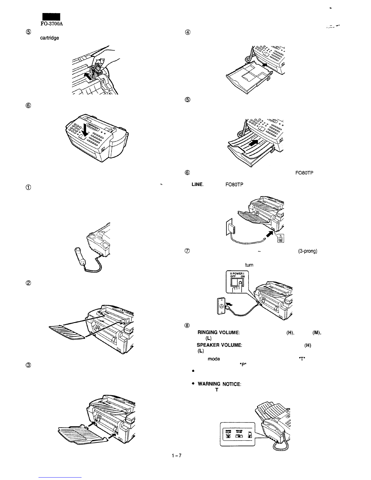
5. Loading printing paper
Selecting paper
The inkjet printer in your FO-3700 is designed to work well with most
types of plain paper. Bond paper generally produces the best results,
and plain paper manufactured for high-quality photocopying is also
good. However, variation in paper composition may significantly af-
fect print quality, and you should therefore test paper (printing on both
sides) before purchasing large quantities to be assured of the quality
you desire.
Size
and
weight
A4 size paper from 60 to 90
g/m*
can be used.
Printing
side
Plain paper has a ‘print’ side which should be used to obtain the best
print quality. The print side is not visible to the naked eye, so check
the label on the end of the package before removing the paper. The
print side will be indicated by an arrow, symbol, or wording. Remove
the number of sheets you wish to use from the package, and load
them in the paper tray print side up as described below.
Note:
Do not use paper which is folded, curled, or tom, as it may jam in the
prfnter.
Loading paper
A maximum of 100 sheets of paper can be loaded in the paper tray.
Note: Do not remove the paper tray from the machine to load paper
(if the tray is not correctly in the machine when paper is
loaded, the paper sensor will not be able to detect the paper).
@
Remove the original document out tray.
@Pull the tray extender out slightly.
@Fan the paper, and then tap the edge against a flat surface to
even the stack.
P
FO-3700A
--+s
@Insert the paper into the tray, print side up.
l
Make sure it fits squarely against the inside of the machine.
@Push the tray extender back in.
l
Make sure it fits snugly against the paper.
@Replace the original document out tray.
About
the
printable
area
The area of the page on which the FO-3700 can print is slightly
smaller than the page itself. The following dimensions are averages,
and there may be slight deviation from these dimensions depending
on how the paper is loaded in the tray.
Printing width: 203 mm
Printing length: The length of the page minus 1.5 mm from the top,
and 12 mm from the bottom.
The FO-3700 has been set at the factory to automatically reduce the
size of received documents to 92%. This can be configured for 100%
reception by user switch. This ensures that data at the extreme edges
of A4 size documents is not lost.
Note: If you receive a document which is too long to be printed on
one sheet of paper, the remainder will be printed on a second
paw.
l-8

[6]
Quick
reference
guide
Use this guide as a convenient reminder for operating the machine after you have read the
detailed instructions for each procedure in the manual. r-----------Y
Note: Steps which are optional are enclosed in a dotted frame:
i
L----.------l
Transmitting documents
Normal
Dialling
I
Redialling
_
-
_
_
-
-
_
Load
+
j
=‘a”-
j
+
Lift handset
document
:
0
:
,-_._---_I
3
Wait for
reception tone
s,ARTlcw”
-
-
-
_
_
-
_
Load
+
i
RE80LuTyxI
i
+
Dial (press
+
document
:o:
numeric keys)
,__--____I
____---__
Load
+
i
“wwm~
j
+
Press Rapid
document
:
0
:
Key
srIRrzw”
_
-
_
_
_
. .
-
_
LOad
j)-REMlmjjSPEEDDLU
Enter Speed Dial
document
10:
0
+
number (press 2
+
1_-_____-1 numeric keys)
Load
document
Making voice calls
Normal
Diailing
Lift handset Lift handset if
press
&AKER
+
Dial (press
numeric keys)
-3
you pressed
SPEAKER
Rapid
Key
Dialling
Lift handset
+
press
Rap’d Lift handset
if
or Key
+
you pressed
press SPEAKER SPEAKER
Speed
Dlalllng
Lift handset
-3-o”+
Lift handset if
or
Enter Speed Dial number
+
you
pressed
press SPEAKER (press 2 numeric keys) SPEAKER
Redialling
77
-b
Lift handset
Operations using the FUNCTION key
3
The following chart shows how
to
access
FUNCTION
key operations. Once you have accessed
$
the desired operation, follow the instructions which appear in the display. 8
*
Answering
machine
settings
‘To
0
0
0
+
# or
YC
(Press until desired itemappears)
Timer
operations
Printing
out
lists
ress
until desired item appears)
Entry
mode
settings
Setting
User
Switches
ress until desired item appears)
Relay
Request
(
ress until desired item appears)
Broadcasting
Multi-copying
YfxD

FO-3700A
.I-
-*
CHAPTER
2.
ADJUSTMENTS
[l]
Adjustments
General
The following adjustments and settings are provided for this model,
make adjustments and/or settings as necessary.
1;.
Adjustments
Adjustments of output voltage (FACTORY ONLY)
1:
Install the power supply unit in the machine.
2:
Set
the
recording paper and document.
3. When the document is loaded, power is supplied to the output
1
lines. Confirm that outputs are within the limits below.
Output voltage settings
I
Output
I
Voltage limits
1
Foctoryad
1
+12v
11.4V
-
12.6V
None
-12v
I
-12.6V
-
-11.4V
None
+5v
VM
(+24V)
1
4.75V
-
5.25V
-23.3V
-
24.7V None
VRI
_
.~
’(Top view)
‘1..
.-
‘:
Connector-
No.
_
CNPW
Pin No.
1
MG
2
MG
3
i24V
4+24V
5DG
6
+5v
7
AG
6
+12v
9
-12v
Fig. 1
2-
2. Settings
(1) Telephone/Fax setting
Perform the following adjustments and settings for the telephone and
facsimile functions.
a) Ringing volume
The desired telephone ring volume can be selected from among
three levels: high, middle, and low.
b) Speaker volume
When the SPEAKER key is pressed, the speaker volume is ad-
justed with this control.
c) Dial mode selector
(tine selector)
Select
P(Pulse)
or T(Tone) according to the type of the telephone
line.
P: Pulse dial telephone mode (10 PPS)
T: Tonedial tone telephone mode (Tone)
3.
IC
protectors
replacement
:
ICPs
(IC Protectors) are installed to protect the
motor.driver
circuit.
ICPs
protect various
ICs
and electronic circuits from an overcurrent.
The location of
ICPs
is shown below: :
CNCCD
I
1
(1)
Fl
(ICP-20) is installed in order to protect
IC’s
from an overcur-
rent generated in the motor drive circuit. If
Fl
is open, replace it
with a new one.
In addition to the replacement of
Fl,
the factor causing
Fl
to
open must also be repaired. If not,
Fl
will open again.
Replacement parts
ICP-N20 (Sharp code: VHVICPNZOI1)

FO-3700A
[2]
Diagnostics
and
service
soft
switches
1. Diagnostics description
(1) Entering the diagnostic mode
Press the keys in the following sequence
)m]+a-+a+@
+@+m,
and the following display will appear.
ROM1
:m
(This code is ROM version name.)
Then press the ‘START/COPY’ key. Select the desired item by
pressing
mar
q
key or rapid key. Press the
LSTARTIC~PY
1
key
to go into the selected diagnostic mode.
(2) Diagnostic items
06
1
PANEL CHECK MODE
07
1
CHECK
PAlTERN
08
1
PROOlJCTtiHECK
09
(
SIGNALSEND MODE
(3) Description of diagnostic items
01
SOFT SWITCH MODE
Used to change the soft switch settings.
After setting soft switch 22, the following display will appear.
[PRINT SFTSW LIST] and
11:
YES OTHER: NO]
Then ‘SOFT SWITCH TABLE’ list is printed by
pressinga
key.
..****t~*.*...*.........*.**.*******~~.*.*.*.*~**.***.**.~~***.~****
l l
.
6oPT6wIfcpTABm
l
.
wo1-00000010 sn1-00000110
.
l
mlO2-00001000
6wl240000000
l
l
wo340000000
5*1340010000
l
.
mo4-00000000 sm4-00000001
l
l
sm5-00000100
811540000010
t
l
8*0640000101
wl6-10001000
l
.
slm7-00001100
sll7-00000000
l
l
8*06-01010010
wlsl10010010
l
l
810940001000
wl9-00010000
l
.
sm0-00000000 w20-10000000
.
t
.
.*.**.*..t***..***.~*.*.**.*...~*.*.*********..***~.***.***.*****.**
02 AU
BLACK
PRINT
Used to check the printer head. All black pattern printable area
of page is printed.
03 ROM
&
RAM CHECK
Used to check the program ROM and the work RAM area of the
machine and the printer, and check the status of the printer. The
ROM check is used for ROM, and a read/write matching test is
used for the
RAM.
-‘-
**
The result of the machine check is given by a number of beeps,
and the total result is given by printing the ‘ROM & RAM
CHECK TABLE’ list.
number of beeps
1
0 beep
1
NO ERROR
r6
beeps
1~
DRAM
ERROR
(opti
I
*tt~.*~~tt*t**ttt.tt*~*****..***.***~*****.**””******..**~.**..*..~*
.
l
l
Ral4lwlc5cx~
l
l
-MUI-
l
.
PLW
-0x
VW..
PCMB
.
l
WAN-ox
l
l
Drwl-w
*
l
OPRWDW(=POSElDP
l
.
l
l
-PP.nmrR-
l
l
Rml
-OK
vru.
AoO.58
l
.
RAN
-011
l
l
OK
OUT OF INK
normal
1
The ink is missing.
04
AUTO FEEDER MODE
Used to check auto feed function by inserting and ejecting docu-
ments.
Place documents in the hopper before entering this mode. then
press the
1sTART/copy[
key to start the test. As the document
sensor is actuated, the document size is displayed.
05
AGING MODE
If a document is placed in the hopper, a copy is taken first. If no
document is present, a sheet of test patterns is printed out every
60 minutes.
(Total 10 sheets)
06
PANEL CHECK MODE
Used to check proper key operation, Each key entry is displayed
on the LCD.
The test results will be also printed.
*****tt**t.*t.t**.**..***~**.***..***.*..*.******.*~...****.**..*.*.
l
l
l
PAlULCEEClSLI6T
l
91
23
4
5
l
l 6
76 9
*
.
l o
:
SO-D-
RXDIAL SOLD
l
l 6PxaKrx
PXSO~IW
POLLIn
ItDmlx PNJl
l
l
6TArwcoPY
P.xcsP’p1044
PwcTIw
01
02
l
l 03 04 05 06 07
.
l
06
09
10
11
12
t
l 13
14
15 16 17
.
l
16
19 20
6mP
l
l
ADTO’
l
PNmLaucxox
l
l
.
.*.**.***..~.*..*.t.~...****.~*.****~.**.~..~~*.*.*..*~*****..****..
2-2

.
07 CHECK PATTERN
Used to check the nozzles of the print head. The following pat-
tern is printed out on the sheet, A total of two sheets will be
produced.
@Frame line:
The frame line shows the print area of a page.
The horizontal ruled line at the lower end is specified with
soft SW 18 bit 3. 4, and 5.
Q
Nozzle test:
The pattern is used to check for a clog in the 46 nozzles of
the print head.
@I
Vertical stripes 1
@Vertical stripes 2
@Light grey
@All-black block:
Three all-black blocks for checking print density
8
All white
@Paper feed accuracy check pattern:
Used to check eccentricity of the paper feed motor.
08
PfloDucTcHEc~
-
(Diags,
07,06,
and 03 take place in succession)
Used to carry out the CHECK PATTERN, PANEL CHECK
MODE, and ROM
&
RAM CHECK CAPITAL CETIERS succes-
sively.
09 SIGNAL SEND MODE
Pressing the [START/COPY
1
key after entering this mode will
transmit modem signals out of the TEL Line, in the following
order. Used to check the modem. (Monitor from (This is also
audible from the speaker of the machine) the TEL line socket to
check signals.)
[l]
No signal (CML signal turn on)
[2] 9600bps(V.29)
[3] 7200bps(V.29)
(41
4600bps(V.27ter)
(51
24OObps(V.27ter)
(61
3OObps(FlAG)
(7
21
OOHz(CED)
[a] 11
OOHz(CNG)
[9]
PSEVDC RINGER
FO-3700A
___a
._
10 MEMORY CLEAR
Used to clear the memory. The soft switches and the user
switches will be set to initial states. The following will be printed.
11
12
FACTORY USE ONLY
FSK SEND MODE
Delivers various signals of 300bps in the following data pattern
at the level set by the soft switch.
ooooo+
11111~010101+11110+00001
13.14. Diag
#13,
#14 are used together.
1. Press the Start key on the receive data unit first then the
send unit.
13 ENTRY DATA SEND
Used to send the data registered in memory by signals of
2400bps, and copy the registering contents.
Registering contents
[l]
rapid number
[2]
speed number
[3]
the contents registered in the entry mode
!(But
date & time is excluded.)
14
[4]
relay
tx
data
[5]
soft switch settings
ENTRY DATA RCV.
This mode is the reception mode of ENTRY DATA SEND. The
received data is registered in the memory, and ‘TELEPHONE
LIST’, ‘PASSCODE LIST’. ‘USER SWITCH LIST’. ‘SOFT
SWITCH LIST’ are printed.
15
TEL. NUMBER SET
The TEL number and name registered in rapid number 01 can
be copied to all rapid numbers. The first 3 characters of the
copied name is changed such as
‘R02’.
Additionafly, the TEL number and name registered in speed
number 01 can be copied to all speed numbers. The first 3
characters of the copied name is changed such as ‘SO2’.
16 CCD ADJUST MODE
Used to execute copy operation. When the
[m)
key is
pressed, the unit goes into the waft state to adjust the CCD line
alignment. When the START/COPY key is pressed again, the
copy operation is resumed.
17
PAPER EXIT MODE
Used to check the recording paper feed function by inserting
and ejecting recording paper. This mode will continue until
recording paper is out, or the
lm
key
is pressed.
18
PRINTER SELF TEST
19
Used to check the state of the printer. This the check prints the
check pattern provided by the printer driver.
INK TEST MODE
Used to check the state of the printer. A check pattern as
with diagnostic 07 is produced when this mode is entered.
2-3

FO-3700A
I-
.0*
2. Soft switch description
Soft switch list
;W Bit Item Switch setting and function Default Note
JO.
No.
1
0
1
Line density choice
FINE
)
STANDARD
0
USER
fax automatic switching switching to fax only
S
W
3
registration
4 Total communication hours and
N
O
Yes 0
pages print
5
Reserved
-
-
0
6Reserved
-
-
0
7CSI transmission Not transmitted transmitted
0
a
Communication error treatment Not transmission error Transmission error
0
d standard contrast
Halftone contrast control
Halftone MTF correction
2-4

FO-3700A
.,---+
8 4
2
1
(Binary)
No.
=5
6
7
a
(Bit No.)
Mode signal transmission level
ON (OVER
-16dBm)
r of Busy tone detection
5
Reduce of copy and manual No.5
00
0
SWITCH
6
receive
No.6 0
1
0
footer off 92 %100%
USER
footer on 91 % 100%
SWITCH
7
Reduce of auto receive
No.7
000
a
No.8
0
1
0
2-5

FO-3700A
DTMF detection time
8 4 2 1 (Binary)
on number of times
PAlTERN
2-6

FO-3700A
--
128
64 32 16 8 4 2
1
(Binary)
23 4 5
6 7 8
(BitNo.)
No.
=
1 2
3
4 (Bit No.)
8 4
2
1 (Binary)
No.=5 8 78 (BitNo.)
Soft switch setup
Soft
swftch
settings stored in memory can be changed by entering
data from the keyboard. SW1 through SW20 constitutes soft
switches. See the soft switch listing on page 2-4 and 2-7 for the
function of
SW1
through SW20 settings.
How to make soft switch
set&ings
To enter the softswitch mode, make the following key entries in se-
quence.
‘FUNCTION’,
V,
‘*‘,
‘8’,
‘#‘,
‘7’.
‘START/COPY’, ‘START/COPY’
SW1 bii No.1 through No.8 will be displayed.
Bit No. 12345678
Make settings in the same way as for SW2. Proceed to the settings of
SW3 to SW20 in the same manner
When the cursor is on SW20 data No.8 position as shown below,
press the
9’
key to finalize all settings.
Bit No.
12345678
Display
SW20
=
,
0
0
0
0
0
0
.$#g
To finish the settings halfway between SW1 and
SW20,
press the
STOP key. in this case, the setting being performed to the SW No. on
display will be nullified while settings perfomted to the preceding SW
Nos. remain in effect.
Display
1
SW01
=
0 0 0 0 0 0 1 0
1
Press the
‘#.
or
•3~’
key and bring the cursor (blinking pointer) to the
bii No. which is to be changed. (The
‘#’
key moves the cursor to the
right, and the
‘*’
key to the left.)
Press the FUNCTION key to change the setting between 1 and 0.
When the cursor is on data No.8 position, press the
V’
key to display
SW2 data No.1 through No.8. pressing the START/COPY button
shifts cursor to the next soft switch
Bit No. 12345678
DiplaY
swo2=
0 0 0 0 1 0 0 0
Soft switch functional description
SW1 No.1 Line density choice
Used to set the transmission mode which is automatically selected
when the MODE key is not pressed. In copy mode, however, the fine
mode is automatically selected unless the MODE key is manually set
to another mode.
0: Standard
1: Fine
default: 0
SW1
No.2.3
Resewed
Set to ‘0’.
2-7

FO-3700A
SW1
No.4 Activity
report
print
This soft switch is used to select; whether or not to print out the
activity report when the memory is full. An activity report can be
printed when the foilowing key entry command is made.
‘FUNCTION’,
‘2’.
‘#‘,
‘START/COPY
After producing the activity report, all the data in the memory will be
cleared.
When the switch function is set to
‘0’
(NO), the data in the memory
will be deleted from the oldest as it reaches the maximum memory
capadty.
0:
NO (first data lost when memory is full)
1: YES (when memory is full)
default
0
SW1
No.5
-
5
Reserved
Set
to
‘0’.
SW1
No.7
Raserved
Set
to ‘I’.
SW1
No.8
Automatic
switching
mode
This soft switch is used to set the auto tek%x select mode or to set
the normal fax mode.
0: Switching to fax only
1: TEL/FAX automatic switching
Default: 0
i
SW2
No.1
Resewed
Set
to
‘0’.
i
SW2 No.2
Reception
4888
BPS
fixed
When line conditions warrant that the reception take place at 4900
BPS repeatedly. It may improve the success of reception to start at
4900 BPS. This improves the receiving document quality and reduces
handshake time due to fallback during training.
0: NO
1: YES
Default: 0
SW2 No.3
Reserved
Set to
‘0’.
SW2 No.4
CED
tone-signal
interval
For international communication, the
219OHz
CED tone may act as
an echo suppresser switch, causing a communication problem.
Though this soft switch is normally set to
‘o’,
it should be set to ‘1’ so
as to change the timer between CED tone and DIS signal from 75ms
to 500ms to eliminate the communication problem caused by echo.
0: 75
ms
1: 5ooms
Default: 0
SW2
No.5
Line
equaber
Used to set the Line equalizer function.
On --f
7.2kn-1
--a
Off-tOh
0:
Off-tOkm
1:
On47.2km
Default: 1
SW2 No.8
-
7
Reserved
Set
to ‘0’.
SW2
No.8
‘NOZZLE
CLOGGED’
display
select
You can select whether the prompt ‘NOZZLE CLOGGED’ is dis-
played or not when nozzie on the printer cartridge dogged.
0: Not display
1: Display
Default: 0
SW3
No.1
MAXpage
length
for
transmit,
receive
and
copy
Used to set the maximum page length.
To avoid possible paper jam, the page length is
non-rally
limited to 1
meter for copy or transmit, and 1.5 metres for receive.
It is possible to set it to ‘No limir to transmit
a-long
document, such
as a computer print from, etc. (In this case, the receiver must also be
set to no limit.)
0:
1 m max. for copy and trensmit,
1,5m
max. for receive (std)
1: No limit
Default: 0
-
4,
._-
SW3
No.2
Footer
print
When set to
‘l’,
the date of reception, the sender’s machine No., and
the page
Noare
automatically recorded at the end of reception.
0: off
1: On
Default: 1
SW3
No.3
Sender’s
phone
number
registration
Used to make a choice of whether the registered sender’s phone
number can be changed or not. If the switch is set to ‘l’, new
registration of the senders phone number is disabled to prevent ac-
cidental wrong input.
0:
canbechanged
1: cannot be changed
Default: 0
SW3
No.4
Total
communication
hours
and
pages
print
Used to make a choice of whether the total communication time and
pages are recorded in the activity report.
0: Yes
1: No
Default: 0
SW3
No.5,8
Resewed
Set to
‘0’.
SW3
No.7
CSI
transmission
CSI signal contains the sender’s phone number registered in the
machine.
0: Transmitted
1: Not transmitted
Default: 0
SW3 No.8
Communication
error
treatment
(reception)
in
RTN
sending
Used to determine communication error treatment when RTN is sent
by occurrence of a received image error in
63
reception. When it is
set to ‘l’, communication error is judged as no error.
0: Transmission error
1: Not transmission error
Default: 0
SW4
No.1
Protocol
Monitor
1
If set to
‘1’.
protocol is printed at communication error.
0: off
1: On
Default: 0
SW4
No.2
Dialing
pause
The length of the pause inserted between telephone numbers of
direct dial contraction. can be adjusted. Selection of 4
set
or 2
set
pause is available.
0:
2smds
1:
4seconds
Default: 0
SW4 No.3
Reserved
Set to
‘0’.
SW4
No.4
NSF
receive
acknowladge
in
G3
transmit
mode
Used to make a choice of whether reception of NSF (DIS) is acknow-
ledged after receiving two
NSFs
(DISs)
or receiving one NSF (two
DISs).
It may be useful for overseas communication to avoid an echo sup-
presser problem, if set to 1
0:
1 for NSF reception, 2 for DIS reception
1:
2times
Default: 0
SW4
No.5
Non-modulation
carrier
in
V29
transmission
moda
Though transmission of non-modulated carrier is not required for
transmission by the V29 modem according to the
CCITT
Recommen-
dation, it may be pemritted to send non-modulation carder before the
image signal to avoid an echo suppresser problem.
It may be useful for overseas communication to avoid an echo sup-
presser problem, if set to 1.
0: No
1: Yes
Default: 0
2-8

I
.
8
Modem
speed
m
mtine the initial modem speed. The default is 9600bps.
i
&essary
to program it to a slower speed when frequent
’
is encountered, in order to save the time required for
!
Ad
‘J29
GBPS
72OOBPS
. V27ter
489OBPS
::
249OBPS
-it. owl
j
No.1
DTMF
3
digits
at
remote
reception
J
to make
a
choice of whether to use the 3 digits code or 2 digits
efor remote receive.
0: No
On+CO+
1: Yes
l*+lOn
,efault
0 5+++503c
:
1
sx49on
W15
No.2
DTMF
datection
cycle/off
time
-,\,’
Used to choose the cycle time and off time.
-’
Normally set to
‘0’.
When the DTMF signal not detected, You
c;an
set
to ‘1’. The DTMF detection is shortened.
0: Cycle time 93ms
Off
time
28ms
1:
Cycletime58ms
Off time 8rns
1
Default: 0
SW15
No.3
A.M
mode
CNG
detecting
Choke is made whether the CNG signal is not detected in
A.M
(Answering machine) mode.
0: Yes
1: No
Default: 0
SW15
No.4
Protection
from
echo
Used to protect from echo in reception.
0: No
1: Yes
Default: 0
SW15
No.5
CNG
detection
time
(Lower
limit)
Used to determine the lower limit of CNG detect time.
0:
ON
325rns
OFF 2450ms
1:
ON225ms
OFF
215Orns
--
Default: 0
SW15
No.8
CNG
detection
time
(Upper
limit)
Used to determine the upper limit of CNG detect time.
0:
ON
675ms
OFF
3559rns
1:
ON775ms
OFF 3859rns
Default: 0
SW15
No.7,8
Number
of
CNG
signal
detection
In
AA
mode
Used for detection of CNG in 1
-
4 pulses in answering machine
mode.
00: 1 time
01: 2 times
10: 3times
11:
4tklles
Default: 10
SW16
No.1
Number
of
CNG
signal
detection
at
the
TEUFAX
automatic
switching
mode
Used for detection of CNG in one or two pulses in the TEL/FAX
automatic switching mode
0: Once
1: Twice
Default: 1
SW1
6
No.2
-
4
Reserved
Set to
‘0’.
SW16
No.5
Time
format
Choice is made for the format of time display
0: 12 hours mode (AM/PM)
1: 24hoursmode
Default: 1
SWIG
No.8,7
Date
format
Used to set entry of date into activity report and LED format accord-
ing to specifications of country.
00: day/month/year
01: month/day/year
10: year/month/day
11:
year/month/day (Japan mode: month is not English)
Default: 00
SW1
6
No.8
Vertical
resolution
Used to set the Vertical resolution.
0: 300 dpi
1: 7.7 line/mm
Default: 0
/
SW1 7 No.1
-
8 Off hook hold
Used to set ‘Off hook hold’ time by binary input.
00000000: 0 second
11111111: 255seconds
Default: 00000000
SW18
No.1
Cut
off
mode
(Copy
mode)
When in copy, if the scanned data is out of the range of recording, the
operator has one of the choices below using the switch.
0:
Continue: Data is printed onto the next page.
1:
Cutoff:
Data scanned out of the limit is cut off.
Default: 1
SW18
No.2
Cut
off
mode
(Corn.
mode)
When receiving, if the data is out of the range of recording, the
operator has one of the choices below using the switch.
0: Continue
1: cutoff
Default: 0
SW18
No.3,4
Paper
select
Used to set the media size. (Letter /A4
/
Legal) check pattern only
00:
Letter size
01: A4
10: Legal
Default: 01
SW18
No.5
Extended
print
area
Used to choose of extended print area enable or disable.
0: Disable
1: Enable
Default: 0
SW18
No.6
-
8
Vertical
scale
method
Used to choose of Vertical scale method.
Method used to create the additional rows needed to provide the
proper vertical size.
099: Blank rows
001: Duplicate last row
010: Smoothing
011: Constant line density (Duplication)
196:
Constant line density (Smoothing)
Default: 010
2-11

FO-3700A
Blank
rows
Duplicate last row
Smoothing
Constant line density using duplication
Constant line density using smoothing
0x03
0 x 04
SW19
No.1
-
4
Number
of
rings
for
auto
receive
When the machine is set in the auto receive mode, the number of
rings before
answer
is made
can-e
selected. It may be set from one
to nine
rings
using
a
binary number. Since the facsimile telephone
could be used as an ordinary telephone if the handset is taken off the
hook before connection is made to the facsimile while ringing, it
should be programmed to the user’s choice. If a facsimile calling beep
is heard when the handset is taken off the hook, press the
START/COPY key and put the handset on the hook to have the
facsimile start receiving. If it is set to above 9, receive rings are
automatically set to 1.
0001: 1 time
I
1001: 9 times
Default: 0001
SW19
No.5
-
8
Automatic
Switching
from
manual
to
auto
receive
mode
Choice is made to after how many rings in the manual receive mode
it should be automaticaily changed to the facsimile answer mode or
remain in the manual receive mode. Entering a binary number 0 will
force the machine to remain in the manual answer mode. If a number
between 1 and 9 is entered, the machine will go into the answer
mode after the given number of rings. However, it can be used as an
ordinary telephone if the handset is taken off the hook before this
programmed number has elapsed. Entry of a number above 9 will set
the machine to 0.
0000: Does not change
0001: 1 times
3.
1001: 9 times
Default: 0000
SW20
No.1
-
4
Dummy
ringer
transmission
level
(dB)
Pseude-ringer sending level setting
OdBm
-
-15dBm.
0000:
OdBm
L
1111: -15dB
Default: 1000 (-8dBm)
SW20
No.5
-
8
Reserved
Set to ‘0’.
SW20
No.7
Remote
operation
auto
disable
Selection of remote operation (5,
*)
inhibition after passing a certain
time from reception of Remote operation auto disable.
0: Not inhibited.
1:
Inhibited automatically after 7 sec.
Default: 0
SW20
No.8
Reserved
Set to ‘0’.
2-12
Table of contents
Other Sharp Fax Machine manuals
Popular Fax Machine manuals by other brands

Panasonic
Panasonic KX-F3000 Service manual and technical guide

Panasonic
Panasonic KXF1050 - FAX operating instructions

Sagem
Sagem PHONEF@X INTERNET 390-i user manual

Konica Minolta
Konica Minolta bizhub C220 Series Operation guide

Brother
Brother FAX-335MCS Specifications

Samsung
Samsung SF-331P Quick install guide