Sharp UX-68 User manual

UX-68DE
FO-78DE
No. 00ZUX68DE/SME
CHAPTER 1. GENERAL DESCRIPTION
[1] Specifications ............................................ 1-1
[2] Operation panel......................................... 1-2
[3] Refer to the service manual of UX-40DE.
[4] Refer to the service manual of UX-40DE.
[5] Quick reference guide ............................... 1-8
CHAPTER 2. ADJUSTMENTS
[1] Adjustments............................................... 2-1
[2] Diagnostics and service soft switch .......... 2-2
[3] Troubleshooting...................................... 2-19
[4] Error code table....................................... 2-20
CHAPTER 3. MECHANISM BLOCKS
[1] Refer to the service manual of UX-40DE.
[2] Refer to the service manual of UX-40DE.
CHAPTER 4. DIAGRAMS
[1] Block diagram ............................................4-1
[2] Wiring diagram .......................................... 4-2
[3] Point-to-point diagram............................... 4-3
CHAPTER 5. CIRCUIT DESCRIPTION
[1] Circuit description...................................... 5-1
[2] Circuit description of control PWB..............5-2
[3] Circuit description of TEL/LIU PWB .......... 5-9
[4] Circuit description of
power supply PWB............................5-12
[5] Circuit description of CIS unit...................5-12
CHAPTER 6. CIRCUIT SCHEMATICS AND
PARTS LAYOUT
[1] Control PWB circuit ................................... 6-1
[2] TEL/LIU PWB circuit ................................. 6-9
[3] Power supply PWB circuit ...................... 6-13
[4] Operation panel PWB circuit ................... 6-15
CHAPTER 7. OPERATION FLOWCHART
[1] Refer to the service manual of UX-40DE.
[2] Refer to the service manual of UX-40DE.
CHAPTER 8. OTHERS
[1] Refer to the service manual of UX-40DE.
[2] Refer to the service manual of UX-40DE.
PARTS GUIDE
CONTENTS
FACSIMILE
UX-68
MODEL FO-78
Parts marked with " " are important for maintaining the safety of the set. Be sure to replace these parts with specified ones for
maintaining the safety and performance of the set.
This document has been published to be used
for after sales service only.
The contents are subject to change without notice.
SHARP CORPORATION
SERVICE MANUAL
Illustration: UX-68
This service manual is omitted because it is partly common to UX-40DE of the service manual of the previous
issue. Those common parts are to refer to the service manual of UX-40DE (00ZUX40DE/SME).

UX-68DE
FO-78DE
(Danish) ADVARSEL !
Lithiumbatteri-Eksplosionsfare ved fejlagtig håndtering.
Udskiftning må kun ske med batteri af samme fabrikat og type.
Levér det brugte batteri tilbage til leverandoren.
(English) Caution !
Danger of explosion if battery is incorrectly replaced.
Replace only with the same or equivalent type
recommended by the equipment manufacturer.
Discard used batteries according to manufacturer’s
instructions.
(Finnish) VAROITUS
Paristo voi räjähtää, jos se on virheellisesti asennettu.
Vaihda paristo ainoastaan laitevalmistajan suosittelemaan
tyyppiin. Hävitä käytetty paristo valmistajan ohjeiden
mukaisesti.
(French) ATTENTION
Il y a danger d’explosion s’ il y a remplacement incorrect
de la batterie. Remplacer uniquement avec une batterie du
même type ou d’un type recommandé par le constructeur.
Mettre au rébut les batteries usagées conformément aux
instructions du fabricant.
(Swedish) VARNING
Explosionsfare vid felaktigt batteribyte.
Använd samma batterityp eller en ekvivalent
typ som rekommenderas av apparattillverkaren.
Kassera använt batteri enligt fabrikantens
instruktion.
(German) Achtung
Explosionsgefahr bei Verwendung inkorrekter Batterien.
Als Ersatzbatterien dürfen nur Batterien vom gleichen Typ oder
vom Hersteller empfohlene Batterien verwendet werden.
Entsorgung der gebrauchten Batterien nur nach den vom
Hersteller angegebenen Anweisungen.
CAUTION FOR BATTERY REPLACEMENT

UX-68DE
FO-78DE
CHAPTER 1. GENERAL DESCRIPTION
[1] Specifications
Automatic dialing: Rapid Key Dialing: 5 numbers
Speed Dialing: 35 numbers
Fax paper: Initial starter roll (included with machine):
10 m
Recommended replacement roll:
FO-20PR, 30m
Modem speed: 9600 bps with automatic fallback to lower
speeds
Transmission time* : Approx. 15 seconds
Resolution: Horizontal: 8 dots/mm
Vertical:
Standard: 3.85 lines/mm
Fine/Halftone: 7.7 lines/mm
Super fine: 15.4 lines/mm
Automatic document feeder: 5 pages max. (80g/cm2paper)
Halftone (grayscale): 64 levels
Display: 16-digit LCD display
Compression scheme: MR, MH, Sharp (H2)
Applicable telephone line: Public switched telephone network/PBX
Compatibility: ITU-T (CCITT) G3 mode
Input document size: Automatic feeding:
Width: 148 to 216 mm
Length: 140 to 297 mm
Manual feeding:
Width: 148 to 216 mm
Length: 140 to 600 mm
Effective scanning width: 210 mm max.
Effective printing width: 210 mm max.
Contrast control: Automatic/Dark selectable
Reception modes: Fax, Tel, Tel/Fax, A.M.
Copy function: Yes
Telephone function: Yes (cannot be used if power fails)
Noise emission: Less than 70 dBA (Measured
according EN 277779 (DIN 45635))
Power requirements: 220-230 V AC, 50 Hz
Operating temperature: 5 - 35°C
Humidity: Maximum: 85 % RH
Power consumption: Standby: 2.6 W
Maximum: 115 W
Dimensions: Width: 304 mm
Depth: 236 mm
Height: 122 mm
Weight: Approx. 2.6 kg
* Basedon ITU-T(CCITT)Test Chart #1 atstandardresolutioninSharp
special mode, excluding time for protocol signals (i.e., ITU-T phase C
time only).
Note: The facsimile machine is Year 2000 compliant.
As a part of our policy of continuous improvement, SHARP reserves the right to make design and specification changes for procduct
improvement without prior notice. The performance specifications figures indicated are nominal values of production units. There may be some
deviation from these values in individual units.
1 – 1

UX-68DE
FO-78DE
[2] Operation panel
1. Zielwahltasten (Rapid Dial keys)
Press one of these keys to dial a fax number automatically.
2. AUFN. (REC/MEMO key)
Press this key to record a phone conversation or a
message.
3. ZURÜCK (REPEAT key)
Press this key to repeat playback of a message.
4. WIEDERG./VOR (PLAY/SKIP key)
Press this key to play recorded messages. During
playback, press it to skip forward to the next message.
5. LCD-Anzeige (Display)
This displays messages and prompts during operation and
programming.
6. LÖSCHEN (DELETE key)
Press this key to erase recorded messages.
7. FUNKTION (FUNCTION key)
Press this key to select various special functions.
8. Taste LAUTSTÄRKE (VOLUME keys)
Press this keys to adjust the volume of the speaker when
the SPEAKER key has been pressed, the volume of the
ringer at all other times.
9. Zifferntasten (Number keys)
Use these keys to dial numbers, and enter numbers and
letters when storing auto-dial numbers.
10. KURZWAHL (SPEED DIAL key)
Press this key to dial a fax or voice number using an
abbreviated 2-digit Speed Dial number.
11. WAHLWDH. (REDIAL key)
Press this key to automatically redial the last number
dialed.
12. Taste START/SPEICHER (START/MEMORY key)
Press this key to send or receive a document or to scan a
document into memory before sending it.
13. Taste STOP (STOP key)
Press this key to cancel operation before it is completed.
14. KOPIE/HILFE (COPY/HELP key)
When a document is in the feeder, press this key to make
a copy of a document. At any other time, press this key to
print out the Help List, a quick reference guide to the
opeation of your fax machine.
15. Taste AUFLÖSUNG/EMPFANGSART
(RESOLUTION/RECEPTION MODE key)
When a document is in the feeder, press this key to adjust
the resolution for faxing or copying. At any other time,
press this key to select the reception mode (an arrow in the
display will point to the currently selected reception mode).
16. LAUTSPR. (SPEAKER key)
Press this key to listen the line and fax tones through the
speaker when faxing a document.
Note: This is not a speakerphone. You must pick up the
handset to talk with the other party.
17. ALPHAWAHL/R (SEARCH/R key)
Press this key to search for an auto-dial number, or, if you
are on a P.B.X. extension, press this key to transfer a call.
18. BEDIENFELD ENTRIEGELN (Panel release)
Grasp this finger hold and pull toward you to open the
operation panel.
TEL FAX
GHI
PQRS
JKL
ABC DEF
MNO
WXYZ
TUV
ABCDE/
STOP
KOPIE/
HILFE
START/
SPEICHER
FUNKTION
LAUTSTÄRKE
KURZWAHL
WAHLWDH.
ALPHAWAHL
LAUTSPR.
AUFLÖSUNG/
EMPFANGSART
123
654
789
0
TEL/FAX ANRUFB.
ABRUF
12
1 8 9 105 7 11
151413 16 1718
R
SYMBOLE
AUFN. ZURÜCK
WIEDERG./VOR
LÖSCHEN
2 3 4 6
1 – 2

UX-68DE
FO-78DE
1 – 8
[5] Quick reference guide
ENTERING YOUR NAME AND NUMBER
1. Press:
FUNKTION
3
Display shows: OWN NUMBER SET
2. Press:
3. Enter your fax number (max. of 20 digits) by pressing the number keys.
•To insert a space between digits, press the # key.To enter "+", press the key.
•If you make a mistake, press the SPEED DIAL key to backspace and clear the
mistake.
4. Press:
5. Enter your name by pressing the appropriate number keys as shown below.
•Toenter twolettersinsuccessionthat requirethe samekey, pressthe SPEAKER
key after entering the first letter.
SENDING FAXES
AUFLÖSUNG/
EMPFANGSART
FAX
TEL
FAX
TEL
05—NOV 10:30
ANRUFB.
TEL/FAX
ANRUFB.
TEL/FAX
05—NOV 10:30
FAX
TEL
FAX
TEL
05—NOV 10:30
ANRUFB.
TEL/FAX
ANRUFB.
TEL/FAX
05—NOV 10:30
START/
SPEICHER
Place your document (up to 5 pages)
face down in the document feeder.
Normal Dialing
1. Lift the handset or press
2. Dial the fax number.
3. Wait for the reception tone (if a person answers, ask them to press their Start
key).
4. Press:
Rapid Key Dialing
Press the appropriate Rapid Key. Transmission will begin automatically.
Speed Dialing
1. Press:
2. Enter 2-digit Speed Dial number.
3. Press:
RECEIVING FAXES
Press the RESOLUTION/RECEPTION MODE key until the arrow in the display
points to the desired reception mode (make sure the document feeder is empty).
LAUTSPR.
KURZWAHL
FAX mode: The fax machine automatically answers on the set number of rings
and receives the incoming document.
TEL mode:
TEL/FAX mode: This mode is convenient for receiving both faxes and voice calls.
When a call comes in, the fax will detect whether it is a voice call (including manu-
ally dialed fax transmissions), or an automatically dialed fax.
A.M. mode: Select this mode when you go out to receive both voice messages
and faxes.
SETTING THE DATE AND TIME
1. Press:
Display shows: DATE & TIME SET
2. Press:
3. Enter two digits for the Day (01 through 31).
4. Enter two digits for the Month (01 through 12).
5. Enter four digits for the Year (Ex: 2000).
6. Enter two digits for the Hour (01 through 23).
7. Enter two digits for the Minute (00 through 59).
8. When finished, press:
STORING AND CLEARING AUTO DIAL NUMBERS
1. Press:
Display shows: FAX/TEL# MODE
2. Press 1to store a number or 2to clear a number.
3. Enter a 2-digit Speed Dial number (from 01 to 05 for Rapid Key Dialing, or 06
to 40 for Speed Dialing) (If you are clearing a number, go to Step 7.)
4. Enter the full fax/telephone number.
5. Press:
6. Enter the name of the location by pressing number keys (Refer to the letter
entry table in
ENTERING YOUR NAME AND NUMBER
.)
7. Press:
A =
B =
C =
D =
E =
F =
G =
H =
I =
J =
K =
L =
M =
N =
O =
P =
Q =
R =
S =
T =
U =
V =
W =
X =
Y =
Z =
SPACE =
•To change case, press the REDIAL key.
Press # or to scroll through symbols and special characters.
6. When finished, press:
START/
SPEICHER
STOP
FUNKTION
3
FUNKTION
3
Beep
START/
SPEICHER
RECEIVING
START/
SPEICHER
START/
SPEICHER
START/
SPEICHER
STOP
START/
SPEICHER
START/
SPEICHER
STOP
START/
SPEICHER
START/
SPEICHER

UX-68DE
FO-78DE
M E M O
1 – 9

UX-68DE
FO-78DE
CHAPTER 2. ADJUSTMENTS
[1] Adjustments
General
Sincethefollowing adjustments and settings are providedfor thismodel,
make adjustments and/or setup as necessary.
1. Adjustments
Adjustments of output voltage (FACTORY ONLY)
1. Install the power supply unit in the machine.
2. Set the recording paper and document.
3. When the document is loaded, power is supplied to the output lines.
Confirm that outputs are within the limits below.
Output voltage settings
2. IC protectors replacement
ICPs (IC Protectors) are installed to protect the motor driver circuit.
ICPsprotect various ICs andelectroniccircuitsfrom an overcurrent con-
dition.
The location of ICPs are shown below:
1DG
2 +5V
3MG
4MG
5 +24V
6 +24V
7DG
8 PSAVE
2 – 1
TEL/LIU PWB POWER SUPPLY PWB
CNL IUA CN2
CNPW
CONTROL PWB
CNL IUB
CNLIUB
CNLIUA
Output Voltage limits
+5V 4.75V ∼ 5.25V
+24V 24.0V ∼ 26.0V
Connector
No. CNPW
Pin No.
CNLIUA CNPW
CONTROL PWB
(TOP SIDE)
CNMT
FU100
CNLIUB
(1)FU100 (KAB2402) is installed in order to protect IC’s from an over-
current generated in the motor drive circuit. If FU100 is open, replace
it with a new one.
3. Settings
Setting is not required since the required mode is TONE ONLY.

UX-68DE
FO-78DE
[2] Diagnostics and service soft switch
1. Operating procedure
(1) Entering the diagnostic mode
Press FUNC →9 →→ 8 →# →7 , and the following display will appear.
ROM Ver. FPB0 After 2 sec: DIAG MODE
FPB0
Then press the START key and country name selected by country select will appear. Select the desired item with the key or the # key or select
with the direct key. Enter the mode with the START key.
(Diag•specifications)
If the diag mode cannot be set, repeat the diag mode operation, per-
forming the following operation.
After the power is turned on and "WAITAMOMENT" is indicated, press
the STOP key.
In relation with the process response (request from Production
Engineering)"WAITAMOMENT"clockindicationmayappeardepending
onSTOPkeytiming.IftheSTOPkey is helddown, "MEMORYCLEAR?"
appears.
FUNC DIAG MODE
9 8 7
START —Soft switch mode
START AROM & RAM check
START —Aging mode
START —Panel check mode
START BCheck pattern
START CSignal send mode
START
START
KEY
STOP
KEY
+
"Power ON"
Memory clear
(Work + Backup)
FPB0
START —Memory clear Shading mode
START
START
All black mode
START
EAuto feeder mode
START
D
Message print
Flash memory check
START
—
—
—
START Flash memory clear
—
START Country selct
—
2 – 2
2. Diagnostic items
ITEM DIRECT
No. key Contents Function
1 — SOFT SWITCH MODE Soft switches are displayed and changed. List can be output.
2 A ROM & RAM CHECK ROM is sum-checked, and RAM is matched. Result list is output.
3 — AGING MODE 10 sheets of check patterns are output every 5 minutes per sheet.
4 — PANEL CKECK MODE Panel keys are tested. Result list is output.
5 B CHECK PATTERN 2 sheets of check patterns are output.
6 C SIGNAL SEND MODE Various signals of FAX communication are output.
7 — MEMORY CLEAR Back-up memory is cleared, and is set at delivery.
8 — SHADING MODE Shading compensation is performed in this mode.
9 D ALL BLACK PRINT To check the print head, whole dots are printed over the interval of 2 m.
10 E AUTO FEEDER MODE Insertion and discharge of document are tested.
11 — MESSAGE PRINT The display message of each language is printed out together with the English equivalent.
12 —
FLASH MEMORY CHECK
Checks flash memory write/read.
13 —
FLASH MEMORY CLEAR
Checks flash memory clearing.
14 — COUNTRY SELECT The software parameter that it agreed in each country name is set up.

UX-68DE
FO-78DE
3. Diagnostic items description
3. 1. Soft switch mode
The soft switches are provided so that each operation mode can be set
by using the operation panel.
In this mode, these switches can be checked and set.
The contents of these switches are backed up.
The available soft switches are SW-A1 to SW-K1.
The content of soft switches is shown in page 2-5 to 2-18.
The contents are set to factory default settings.
3. 2. ROM & RAM check
ROM executes the sum check, and RAM executes the matching test.
The result will be notified with the number of short sounds of the buzzer
as well as by printing the ROM & RAM check list.
Number of short sounds of buzzer 0 →No error
1 → ROM error
2 → RAM error (32Kbyte)
3. 3. Aging mode
If any documentisfirst present,copyingwill beexecutedsheet by sheet.
If no document is present, the check pattern will be printed sheet by
sheet. This operation will be executed at a rate of one sheet per 5min-
utes, and will be ended at a total of 10 sheets.
3. 4. Panel check mode
This mode is used to check whether each key operates properly or not.
Press the key on the operation panel, and the key will be displayed on
thedisplay.Therefore,pressallkeys.Atthistime,finallypress the STOP
key.
When the STOP key is pressed, the keys which are not judged as
"pressed" will be printed on the result list.
• LED part of the contact image sensor (CIS) is kept on during the term
fromwhen "START"of the panel testmode to end withthe STOPkey.
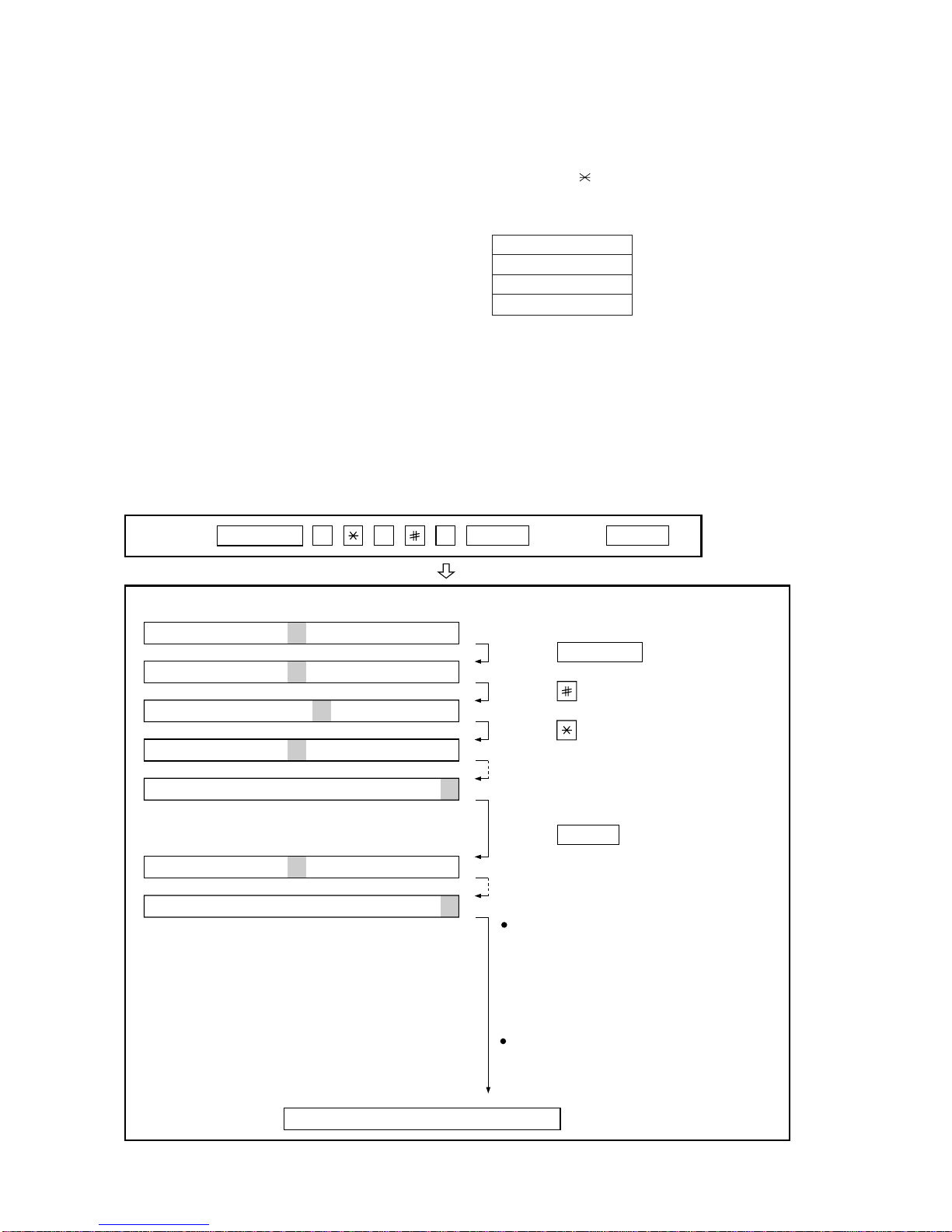
3. 5. Check pattern
Thismode is used to checkthe status of print head.Twosheetsofcheck
patternare printed. The following informationof check pattern is printed.
1
Vertical stripes (alternate white and black lines) Approx. 35 mm
2
Full black Approx. 70 mm
3
Full white Approx. 35 mm
3. 6. Signal send mode
This mode is used to send various signals to the circuit during FAX com-
munication. Every push of START key sends a signal in the following
sequence.Moreover,thesignalsoundisalsooutput to the speaker when
the line monitor of the soft switch is on.
[1] No signal (CML signal turned on)
[2] 9600bps
[3] 7200bps
[4] 4800bps
[5] 2400bps
[6] 300bps (FLAG)
[7] 2100Hz (CED)
[8] 1100Hz (CNG)
[9] Pseudo Ring (models with auto TEL/FAX changeover function)
[10] END
3. 7. Memory clear
This mode is used to clear the backup memory and to reset to the fac-
tory default settings.
The content of each setting will be cleared.
Note: Be sure to execute the memory clear mode whenever you change
the country select setting. The default settings of the soft switches
varyaccording to the destinations.Therefore, if you do not execute
the memory clear after changing the country select setting, some
functions may not work.
3. 8. Shading mode
The mode is used for the shooting compensation. For reading, set up
the special original paper.
The shooting compensation memorizes the reference data of white and
black for reading.
Moreover, the memorized data is not erased even if memory clear mode
is executed.
3. 9. All black print
This mode is used to check the state of the printing head and inten-
tionally overheat it. Whole dots are printed over the interval of 2 m. If it is
overheatedor the printing sheet is jammed, press STOP key for the end.
3. 10. Auto feeder mode
In this mode, a document is inserted and discharged to check the auto
feed function.
After this mode is started, set a document, and the document feed will
be automatically tested.
2 – 3
1
2
3
RANK 0 or 1
Note:
There is a selection RANK 0 or 1 depending on resistance value of the
thermal head. RANK 0 or RANK 1 is printed at the tail of check pattern
to identify.

UX-68DE
FO-78DE
3. 11. Message print
Usedtoprintthedisplayedmessage of communication for translate each
language.
3. 12. Flash memory check
Data is written into and read from the flash memory to check the data
conformity. When the unit enters this mode, the check is started.
3. 13. Flash memory clear
Data in the flash memory is cleared (memory clear). When the unit en-
ters this mode, the check is started.
*Operation of hardware and signal in the flash memory check mode and
flash memory clear mode, and the result of check.
The result is announced by the buzzer beeps. The result of check is
printed.
Beeps
0 →No error
1 →Memory error
2 – 4
Press FUNCTION 9 8 7 STARTSTART
Press FUNCTION key.
Press key.
Press key.
Bit1 - 8 are set.
Soft SW-A2 - SW-K1 are set.
S F T SW-A1 = 1 0 0 0 0 0 0 0
S F T SW-A2 = 0 0 0 0 0 0 0 0
S F T SW-K1 = 0 0 0 0 0 0 0 0
Press key during setting.
To finish the settings halfway between
SW-A1 and SW-K1, press the STOP
key. In this case, the setting being done
to the SW No. on display will be nullified
while settings done to the preceding
SW Nos. remain in effect.
The soft switch mode is terminated.
S F T SW-A1 = 0 0 0 0 0 0 0 0
START
DATA No. 1 2 3 4 5 6 7 8
When the COPY key is pressed, the
contents of soft switches are printed.
3. 14. Country select
This mode is used to set line connecting parameters which correspond
to each destination.
When the country select mode is selected, and then the START key is
pressed, the destination (country name) currently set will be displayed.
By pressing the # or key, selectable destinations (country names) are
displayed. When the destination (country name) you want to choose is
displayed, press the START key. Each parameter will be stored in RAM.
Destinations (Country names) you can select are as follows:
COUNTRY NAME
AUSTRIA (AT)
GERMANY (DE)
FRANCE (F)
Note: Be sure to execute the memory clear mode whenever you
change the country select setting. The default settings of the
soft switches vary according to the destinations. Therefore, if
you do not execute the memory clear after changing the coun-
try select setting, some functions may not work.
Do not set a country select setting which is different from that
of the destination of the machine. Some functions will not work
because the function and the PWB specifications are different.
4. How to make soft switch setting
To enter the soft switch mode, press the following key entries in se-
quence.

UX-68DE
FO-78DE
1 Protect from echo No Yes 0
2 Forced 4800bps reception Yes No 0
3 Footer Print Yes No 0
4 Length limitation of copy/send/receive No limit Copy/Send:60cm 0
Receive:1.5m
5 CSI transmission Not transmitted Transmitted 0
6 DIS receive acknowledgement during G3 Twice NSF:Once 0
transmission DIS:Twice
7 Non modulated carrier for V29 transmission Yes No 0
mode
8 Reserved 0
Modem speed V.29 V.27 ter
9600bps 7200bps 4800bps 2400bps
1 No. 1 0 0 0 0 0
2 No. 2 0 0 0 0 0
3 No. 3 0 1 1 0 0
4 No. 4 1 1 0 0 1
5 Reserved 0
6 H2 mode No Yes 0
7 Communication error treatment in RTN No communication error Communication error 0
sending mode(Reception)
8 CNG transmission No Yes 0
CED tone signal interval 1000ms 750ms 500ms 75ms
1 No. 1 1 1 0 0 0
2 No. 2 1 0 1 0 0
3 MR Coding No Yes 0
4 Reserved 0
5 Reserved 0
6 Reserved 0
7 Reserved 0
8 Reserved 0
1 Signal Transmission level Binary input 0
2 (0~-31 dBm setting by 1dBm step) No. = 16 8 4 2 1 1
3 1 2 3 4 5 0
4 0 1 0 0 0 0
5 0
6 Protocol monitor(Error print) Printed at com. error Not printed 0
7 Protocol monitor Yes No 0
8 Line monitor Yes No 0
Digital equalization setting(Reception) 7.2km 0km
1 No. 1 1 0 1
2 No. 2 1 0 1
Digital equalization setting(Transmitter) 7.2km 0km
3 No. 3 1 0 0
4 No. 4 1 0 0
Digital equalization setting(Reception 7.2km 0km
5 for Caller ID) No. 5 1 0 0
6 No. 6 1 0 0
7 Error criterion 10 ~ 20 % 5 ~ 10 % 0
8 Anti junk fax check Yes No 1
5. Soft switch description
• Soft switch
SW
NO. DATA
NO. ITEM Switch setting and function
10
SW
l
A1
SW
l
A2
SW
l
A3
2 – 5
SW
l
A4
SW
l
A5
Remarks
Initial
setting

UX-68DE
FO-78DE
1 Auto gain control(MODEM) Enable Disable 1
2 End Buzzer Yes No 1
3
Disconnect the line when DIS is received in RX mode
No Yes 1
4 Equalizer freeze control(MODEM) On Off 0
5 Equalizer freeze control 7200 bps only No Yes 0
6 CNG transmission in manual TX mode Yes No 1
7
Initial compression scheme for sharp fax in TX mode
MR mode H2 mode 0
8 Modem speed automatic down when RX Yes No 0
level is under -40dBm
EOL detect timer 5 seconds 13 seconds 20 seconds25 seconds
1 No. 1 0 0 1 1 0
2 No. 2 0 1 0 1 1
3 Reserved 0
4 Reserved 0
5 Reserved 0
6 Reserved 0
7 Reserved 0
8 Reserved 0
1 Reserved 0
2 Auto dial fax transmission by REDIAL key Yes No 0
3 Reserved 0
4 Recall interval Binary input 0
5 (0~15.5min setting by 0.5min step) No. = 16 8 4 2 1 1
6 4 5 6 7 8 0
7 0 1 0 1 0 1
8 0
1 Recall times(0~15times setting) Binary input 0
2 No. = 8 4 2 1 0
3 1 2 3 4 1
4 0 0 1 0 0
5 Dial tone detection(Before auto dial) No Yes 1
6 Reserved 0
7 Busy tone detection(After auto dial) No Yes 1
8 Busy tone detection pulse number 4 pulses 2 pulses 0
(After auto dial)
Waiting time after dialing
45 seconds 55 seconds 90 seconds 140 seconds
1 No. 1 0 0 1 1 1
2 No. 2 0 1 0 1 0
3 PBX connection Yes No 0 OPTION
4 Reserved 0
PBX recall function(R key select) NO OPERATION FLASH
5 No. 5 0 1 1
6 No. 6 0 1 1
PBX select ID FLASH OPTION
7 No. 7 0 1 0
8 No. 8 0 1 0
1 Dial pausing(sec/pause) 4 sec 2 sec 1
2 Dial mode Tone Pulse 1
3 Pulse →Tone change function by key Enable Disable 1
4 Dial pulse make/break ratio(%) 40/60 33/67 1
Auto dial mode Delay timer of before line
0 second 1.5 seconds 3.0 seconds 4.5 seconds
5 connect No. 5 0 0 1 1 0
6 No. 6 0 1 0 1 1
7 Reserved 0
8 Reserved 0
SW
NO. DATA
NO. ITEM Switch setting and function
10
SW
l
A6
2 – 6
Remarks
Initial
setting
SW
l
B3
SW
l
B2
SW
l
A7
SW
l
B1
SW
l
B4

UX-68DE
FO-78DE
Auto dial mode Delay timer of after line 1.7s 2.0s 2.5s 3.0s 3.6s 4.0s 5.5s 7.0s
1 connect No. 1 0 0 0 0 1 1 1 1 1
2 No. 2 0 0 1 1 0 0 1 1 0
3 No. 3 0 1 0 1 0 1 0 1 1
4
Fax signal detection after telephone mode dial
Yes No 0
5
Recalling fixed only one time when dialing was
Yes No 0
unsuccessful without detecting busy tone signal
6 Reserved 0
7 Reserved 0
8 Reserved 0
1 DTMF signal transmission level Binary input 1
2 (Low frequency 0~15.5dBm setting No. = 16 8 4 2 1 0
3 by 0.5dBm step) 1 2 3 4 5 0
4 1 0 0 0 1 0
5 1
6 Reserved 0
7 Reserved 0
8 Reserved 0
1 DTMF signal transmission level Binary input 0
2 (High frequency 0~15.5dBm setting No. = 16 8 4 2 1 1
3 by 0.5dBm step) 1 2 3 4 5 1
4 0 1 1 0 0 0
5 0
6 Reserved 0
7 Reserved 0
8 Reserved 0
Reading Slice(Binary) Factory Dark Light
Daker in
setting dark
1 No. 1 0 0 1 1 0
2 No. 2 0 1 0 1 0
Reading Slice(Half tone) Factory Dark Light
Daker in
setting dark
3 No. 3 0 0 1 1 0
4 No. 4 0 1 0 1 0
5 Line density selection Fine Standard 0
6 Reserved 0
7 MTF correction in half tone mode No Yes 0
8 Reserved 0
1 Number of rings for auto receive Binary input 0 OPTION
2 (0~15rings setting) No. = 8 4 2 1 0
3 1 2 3 4 1
4 0 0 1 0 0
5 Automatic swiching manual to auto receive Yes No 0
function
CI detect frequency
As PTT 11.5Hz 13.0Hz 20.0Hz
6 No. 6 0 0 1 1 0
7 No. 7 0 1 0 1 0
8 Reserved 0
2 – 7
SW
NO. DATA
NO. ITEM Switch setting and function
10
SW
l
B5
SW
l
B6
SW
l
B7
SW
l
C1
SW
l
D1
Remarks
Initial
setting

UX-68DE
FO-78DE
1 Reserved 0
2 Reserved 0
3 Reserved 0
4 Reserved 0
5 Reserved 0
6 Caller ID function Yes No 0 OPTION
7 Reserved 0
8 Reserved 0
1 CI off detection timer Binary input 0
2 (0~1550ms setting by 50ms step) No. = 16 8 4 2 1 1
3 1 2 3 4 5 1
4 0 1 1 1 0 1
5 0
6 Reserved 0
7 Reserved 0
8 Reserved 0
1 DTMF type Caller ID RX level Binary input 1
2 (0~-44dBm setting by 1dBm step) No. = 32 16 8 4 2 1 0
3 1 2 3 4 5 6 1
4 1 0 1 1 0 0 1
5 0
6 0
7 Reserved 0
8 Reserved 0
Pseudo ringing time at the TEL/FAX
9sec 15sec 30sec 60sec 90sec 120sec 150sec 180sec
1 automatic switching mode No. 1 0 0 0 0 1 1 1 1 0
2 No. 2 0 0 1 1 0 0 1 1 1
3 No. 3 0 1 0 1 0 1 0 1 0
4 Number of CNG signal detection at the Twice Once 1
TEL/FAX automatic switching mode
5 CNG detect time at TEL/FAX mode 3 sec 5 sec 0
6 Post answer tone(TEL/FAX mode) No Yes 1
7 Type of post answer tone LA-SI-DO tone 800Hz single tone 0
8 Pseudo ringer ON/OFF cycle 1 sec ON / 4 sec OFF 1 sec ON / 2 sec OFF 1
1 Pseudo ringer sound output level to the line Binary input 1
2 (0~-15dBm setting by 1dBm step) No. = 8 4 2 1 0
3 1 2 3 4 1
4 1 0 1 0 0
Post answer tone transmission level Binary input
5 (0~-15dBm setting by 1dBm step) No. = 8 4 2 1 1
6 5 6 7 8 0
7 1 0 0 1 0
8 1
1 Reserved 0
Action select when DTMF "#" is received during
A.M. Remote
phone/fax automatic switching mode
No Action No Action
operation
Disconnect line
2 No. 2 0 0 1 1 0
3 No. 3 0 1 0 1 0
4 Reserved 0
5 Reserved 0
6 Reserved 0
7 Reserved 0
8 Reserved 0
SW
NO. DATA
NO. ITEM Switch setting and function
10
2 – 8
Remarks
Initial
setting
SW
l
D2
SW
l
D3
SW
l
D4
SW
l
E1
SW
l
E2
SW
l
E3

UX-68DE
FO-78DE
DTMF detection time 50ms 80ms 100ms 120ms
1 No. 1 0 0 1 1 0
2 No. 2 0 1 0 1 0
3 Protection of remote reception(5 ) Yes No 0
detection
4 Remote reception with GE telephone Compatible Not compatible 1
5 Remote operation code figure by external Binary input 0 OPTION
6 TEL (0~9) No. = 8 4 2 1 1
7 5 6 7 8 0
8 0 1 0 1 1
1 CNG detection in STAND-BY mode Yes No 1 OPTION
Number of CNG detect(AM mode) 1 pulse 2 pulses 3 pulses 4 pulses
2 No. 2 0 0 1 1 0
3 No. 3 0 1 0 1 1
Number of CNG detect(STAND-BY mode) 1 pulse 2 pulses 3 pulses 4 pulses
4 No. 4 0 0 1 1 0
5 No. 5 0 1 0 1 1
6 Reserved 0
7 Reserved 0
8 Reserved 0
1 Reserved 0
2 Reserved 0
3 Reserved 0
4 Reserved 0
5 Reserved 0
6 Reserved 0
7 Reserved 0
8 Reserved 0
1 Reserved 0
2 Reserved 0
3 Reserved 0
4 Reserved 0
5 Reserved 0
6 Reserved 0
7 Reserved 0
8 Reserved 0
1 Reserved 0
2 Reserved 0
3 Reserved 0
4 Reserved 0
5 Reserved 0
6 Reserved 0
7 Reserved 0
8 Reserved 0
1 Quiet detect level setting Binary input 1
2 (0~-44dBm setting by 1dBm step) No. = 32 16 8 4 2 1 0
3 1 2 3 4 5 6 1
4 1 0 1 1 0 0 1
5 0
6 0
7 Fax switching when A.M. full Yes No 0 OPTION
8 Reserved 0
SW
NO. DATA
NO. ITEM Switch setting and function
10
2 – 9
SW
l
F1
SW
l
F2
SW
l
G1
SW
l
G2
SW
l
G3
SW
l
G4
Remarks
Initial
setting

UX-68DE
FO-78DE
1 Busy tone continuous sound detect time 5sec 10sec 1
2 Busy tone detect continuation sound detect No Yes 1
during OGM
3 Busy tone detect continuation sound detect No Yes 0
4 Busy tone detect intermittent sound detect No Yes 1
during OGM
5 Busy tone detect intermittent sound detect No Yes 0
Busy tone detection pulse number 2pulses 4pulses 6pulses 10pulses
6 No. 6 0 0 1 1 0
7 No. 7 0 1 0 1 1
8 Reserved 0
1 Reserved 0
2 Reserved 0
3 Reserved 0
4 Reserved 0
5 Reserved 0
6 Reserved 0
7 Reserved 0
8 Reserved 0
ICM recording time 4min 15s 30s 60s OPTION
1 No. 1 0 0 1 1 0
2 No. 2 0 1 0 1 0
A.M. Quiet time 1 2s 3s 4s 5s
3 No. 3 0 0 1 1 0
4 No. 4 0 1 0 1 0
A.M. Quiet time 2 0s 1s 2s 3s
5 No. 5 0 0 1 1 1
6 No. 6 0 1 0 1 0
7 Key input buzzer on/off switch On Off 0
(Two way recording mode)
8 Reserved 0
A.M. Quiet detect time Binary input
1 No. = 16 8 4 2 1 0
2 1 2 3 4 5 0
3 0 0 1 1 0 1
4 1
5 0
6 Reserved 0
7 Reserved 0
8 Reserved 0
1 Two way alarm Yes No 1
2 Max OGM record time 15s 60s 0
3 Two way record function Disable Enable 0
4 Toll saver Disable Enable 0 OPTION
5 FAX reception in case of detecting No sound Yes No 1
detect after ICM recording
6 Reserved 0
7 Reserved 0
8 Transfer dial recall Disable Enable 0
SW
l
H1
SW
l
H2
SW
NO. DATA
NO. ITEM Switch setting and function
10
2 – 10
Remarks
Initial
setting
SW
l
I3
SW
l
I1
SW
l
I2

UX-68DE
FO-78DE
AGC Maximum Gain (line) 10~25dB (1dB step)
Binary input
1 No. = 8 4 2 1 1
2 1 2 3 4 1
3 1 1 0 0 0
4 0
AGC Maximum Gain (mic) 10~25dB (1dB step)
Binary input
5 No. = 8 4 2 1 1
6 5 6 7 8 1
7 1 1 1 1 1
8 1
AGC Eref access code (line) -0~-30dB (2dB step)
Binary input
1 No. = 8 4 2 1 1
2 1 2 3 4 1
3 1 1 0 1 0
4 1
AGC Eref access code (mic) -0~-30dB (2dB step)
Binary input
5 No. = 8 4 2 1 1
6 5 6 7 8 1
7 1 1 1 1 1
8 1
AGC
Gain Adaptation Threshold (line) Binary input
1 No. = 8 4 2 1 1
2 1 2 3 4 1
3 1 1 1 1 1
4 1
AGC
Gain Adaptation Threshold (mic) Binary input
5 No. = 8 4 2 1 1
6 5 6 7 8 1
7 1 1 1 1 1
8 1
AGC
Slew Rate (line) Slow Normal Little fast Fast
1 No. 1 0 0 1 1 0
2 No. 2 0 1 0 1 1
AGC
Slew Rate (mic) Slow Normal Little fast Fast
3 No. 3 0 0 1 1 0
4 No. 4 0 1 0 1 1
5 Reserved 0
6 Reserved 0
7 Reserved 0
8 Reserved 0
OGM/ICM output level (0~-31dBm setting by Binary input
1 1dBm step) No. = 16 8 4 2 1 0
2 1 2 3 4 5 0
3 0 0 1 0 1 1
4 0
5 1
6 AM OGM announce only mode Yes No 0 OPTION
7 Reserved 0
8 Reserved 0
SW
l
I4
SW
NO. DATA
NO. ITEM Switch setting and function
10
2 – 11
SW
l
I5
SW
l
I6
SW
l
I8
SW
l
I7
Remarks
Initial
setting

UX-68DE
FO-78DE
1 Sender’s phone number setting Cannot change Change allowed 0
2 Summer time No Yes 0
Ringer volume Off Low Middle High OPTION
3 No. 3 0 0 1 1 1
4 No. 4 0 1 0 1 0
5 Reserved 0
6 Reserved 0
7 Polling key Yes No 0 OPTION
8 Reserved 0
1 Reserved 0
2 Reserved 0
Speaker volume Very Low Low Middle High Very High OPTION
3 No. 3 0 0 0 0 1 0
4 No. 4 0 0 1 1 0 1
5 No. 5 0 1 0 1 0 0
6 Speaker monitor function Yes No 1
7 Saving energy start timing 5sec 180sec 0
8 Saving energy mode Enable Disable 1
Communication results printout Error Send only Always No print OPTION
1(Transaction report) No. 1 0 0 0 0 0
2 No. 2 0 0 1 1 0
3 No. 3 0 1 0 1 0
4 Time format 12 hour 24 hour 0
5 Date format Month-Day-Year Day-Month-Year 0
6 Reserved 0
7 Reserved 0
8 Reserved 0
1 Entering diag mode by pressing SPEED key Yes No 0
2 Reserved 0
3 Reserved 0
4 Reserved 0
5 Reserved 0
6 Reserved 0
7 Reserved 0
8 Reserved 0
SW
NO. DATA
NO. ITEM Switch setting and function
10
2 – 12
SW
l
J1
SW
l
J2
Remarks
Initial
setting
SW
l
J3
SW
l
K1

UX-68DE
FO-78DE
• Soft switch function description
SW-A1 No. 1 Protect from echo
Used to protect from echo in reception.
SW-A1 No. 2 Forced 4800BPS reception
When line conditions warrant that receptions take place at 4800 BPS
repeatedly.
It may improve the success of receptions by setting at 4800BPS.
This improves the receiving document quality and reduces handshake
time due to fallback during training.
SW-A1 No. 3 Footer print
When set to "1", the date of reception, the sender machine No., and the
page No. are automatically recorded at the end of reception.
SW-A1 No. 4 Length limitation of copy/send/receive
Used to set the maximum page length.
To avoid possible paper jam, the page length is normally limited to 0.6
meter for copy or transmit, and 1.5 meters for receive.
It is possible to set it to "No limit" to transmit a long document, such as a
computer print form, etc. (In this case, the receiver must also be set to
no limit.)
SW-A1 No. 5 CSI transmission
(CSI TRANSMISSION) is a switch to set whether the machine sends or
does not send the signal (CSI signal) informing its own telephone No. to
theremotefaxmachinewheninformationis received. When "nonsending"
is set, the telephone No. is not output on the remote transmitting ma-
chine if the remote transmitting machine has the function to display or
print the telephone No. of receiving machine, using this CSI signal.
SW-A1 No. 6 DIS receive acknowledgment during G3 transmission
Used to make a choice of whether reception of DIS(NSF) is acknowl-
edged after receiving two DISs(NSFs) or receiving one DIS (two NSFs).
It may be useful for overseas communication to avoid an echo suppres-
sion problem, if set to 1.
SW-A1 No. 7 Non modulated carrier for V29 transmission mode
Thoughtransmission of a nonmodulated carrier is not required for trans-
missionby the V29 modem according to the CCITT Recommendation, it
may be permitted to a send nonmodulated carrier before the image sig-
nal to avoid an echo suppression problem.
It may be useful for overseas communication to avoid an echo suppres-
sion problem, if set to 1.
SW-A1 No. 8 Reserved
Set to "0".
SW-A2 No. 1 ~ No. 4 Modem speed
Used to set the initial modem speed. The default is 9600BPS.
It may be necessary to program it to a slower speed when frequent line
fallback is encountered, in order to save the time required for fallback
procedure.
SW-A2 No. 5 Reserved
Set to "0".
SW-A2 No. 6 H2 mode
Used to determine reception of H2 mode (15 sec transmission mode).
When set to OFF, H2 mode reception is inhibited even though the trans-
mitting machine has H2 mode function.
SW-A2 No. 7 Communication error treatment in RTN sending mode
(Reception)
Used to determine communication error treatment when RTN is sent by
occurrence of a received image error in G3 reception. When it is set to
"1", communication error is judged as no error.
SW-A2 No. 8 CNG transmission
When set to "0", this model allows CNG transmission by pressing the
Start key in the key pad dialing mode. When set to "1", CNG transmis-
sion in the key pad dialing mode cannot be performed. In either case,
CNG transmission can be performed in the auto dial mode.
2 – 13
TX RX
CED
DIS
T
SW-A3 No. 1, No. 2 CED tone signal interval
For international communication, the 2100Hz CED tone may act as an
echo suppression switch, causing a communication problem.
Though SW-A3 No. 1 and No. 2 are normally set to 0, this selfing is used
to change the time between the CED tone signal to eliminate the com-
munication caused by echo.
SW-A3 No. 3 MR coding
Used to select the MR coding enable or disable.
SW-A3 No. 4 ~ No. 8 Reserved
Set to "0".
SW-A4 No. 1 ~ No. 5 Signal transmission level
(0~-31 dBm setting by 1dBm step)
Used to control the signal transmission level in the range of -0dB to
-31dB.
The factory setting is at -11dB(HK), -9dB(SG) (MODEM output).
SW-A4 No. 6 Protocol monitor (Error Print)
If set to "1", protocol is printed at communication error.
SW-A4 No. 7 Protocol monitor
Normally set to "0". If set to "1", communication can be checked, in case
of trouble, without using a G3 tester or other tools.
When communication FSK data transmission or reception is made, the
datais taken into thebuffer.Whencommunicationis finished, the datais
analyzed and printed out. When data is received with the line monitor
(SW4-No. 8) set to "1" the reception level is also printed out.
SW-A4 No. 8 Line monitor
Normally set to "0". If set to "1", the transmission speed and the recep-
tion level are displayed on the LCD. Used for line tests.
SW-A5 No. 1, No. 2 Digital equalization setting (Reception)
Line equalization when reception is to be set according to the line char-
acteristics.
Setting should be made according to distance between the telephone
and the telephone company central switching station.
SW-A5 No. 3, No. 4 Digital equalization setting (Transmitter)
Line equalization when transmission is to be set according to the line
characteristics.
Setting should be made according to distance between the telephone
and the telephone company central switching station.
SW-A5 No. 5, No. 6 Digital equalization setting
(Reception for Caller ID)
Line equalization when reception for CALLER ID is to be set according
to the line characteristics.
Setting should be made according to distance between the telephone
and the telephone company central switching station.
SW-A5 No. 7 Error criterion
Used to select error criterion for sending back RTN when receiving im-
age data.
SW-A5 No. 8 Anti junk fax check
When using the Anti junk fax function, set to "1".
SW-A6 No. 1 Auto gain control(MODEM)
When this mode is enabled, if the reception signal level is under 31dBm,
the modem itself controls the signal gain automatically.
SW-A6 No. 2 End buzzer
Settingthisbit to 0 will disable the end buzzer(includingthe error buzzer/
on-hook buzzer).

UX-68DE
FO-78DE
SW-A6 No. 3 Disconnect the line when DIS is received in RX mode
Bit1 = 0 : When DIS signal is received during RX mode, disconnect the
line immediately.
Bit1 = 1 : When DIS signal is received during RX mode, wait for the next
signal.
SW-A6 No. 4 Equalizer freeze control (MODEM)
This switch is used to perform reception operation by fixing the equal-
izer control of modem for the line which is always in unfavorable state
and picture cannot be received.
* Usually, the control is executed according to the state of line where the
equalizer setting is changed always.
SW-A6 No.5 Equalizer freeze 7200BPS only
SettingwhichspecifiesSW-A6No.4controlonlyinconditionof7200BPS
modem speed.
SW-A6 No. 6 CNG transmission in manual TX mode
When set to "1", fax transmit the CNG signal in case of manual
transmissiom mode (User press the START key after waiting for the fax
answering signal from handset or speaker).
SW-A6 No. 7 Initial compression scheme for sharp fax in TX mode
When set to "0", if the other fax is Sharp model, fax transmit the docu-
ment by H2 mode.
When set to "1", even if the other fax is Sharp model, fax transmit the
document by MR mode.
SW-A6 No. 8 Modem speed automatic down when RX level is under
-40dBm
When set to "1", if fax signal level is under -40dBm during reception,
machine selects the slower modem speed automatically.
It is effective when noises occur on the received document due to the
long distance communications.
SW-A7 No. 1, No. 2 EOL (End Of Line) detect timer
Usedto make a choice of whether to use the 5 or 13 or20 or 25 seconds
timer for detection of EOL.
This is effective to override communication failures with some facsimile
models that have longer EOL detection.
SW-A7 No. 3 ~ No. 8 Reserved
Set to "0".
SW-B1 No. 1 Reserved
Set to "0".
SW-B1 No. 2 Auto dial fax transmission by REDIAL key
When set to "1", if original documents are set to the feeder and you
press REDIAL key, machine will dial and transmit the ducuments auto-
matically.
When set to "0", operator needs to press the START key after FAX re-
ception tone is heard.
SW-B1 No. 3 Reserved
Set to "0".
SW-B1 No. 4 ~ No. 8 Recall interval
(0~15.5min setting by 0.5min step)
Choice is made for a redial interval for speed and rapid dial calls.
Use a binary number to program this with 0.5min steps. If set to 0 acci-
dentally, 0.5min will be assumed.
SW-B2 No. 1 ~ No.4 Recall times (0~15times setting)
Choice is made as to how many redials there should be.
SW-B2 No. 5 Dial tone detection (Before auto dial)
Used to set YES/NO of dial tone detection in auto dialing.
SW-B2 No. 6 Reserved
Set to "0".
SW-B2 No. 7 Busy tone detection (After auto dial)
Used to set YES/NO of busy tone detection after auto dialing.
SW-B2 No. 8 Busy tone detection pulse number (After auto dial)
Used for detection of busy tone in 2 or 4 pulses.
SW-B3 No. 1, No. 2 Waiting time after dialing
This is waiting time for the opponent's signals after dialing.
45 / 55 / 90 / 140 seconds settings are available.
SW-B3 No. 3 PBX connection
Used to select according to the connected line: PBX (Private Branch
Exchange).
SW-B3 No. 4 Reserved
Set to "0".
SW-B3 No. 5, No. 6 PBX recall function (R key select)
Usedto set the operation modeof PBX recall when theR key is pressed.
Setting is made according to the type of PBX.
No. 5=1, No. 6=1:Time break recall (=Flash) is performed.
SW-B3 No. 7, No. 8 PBX select
Used to select the operation mode of PBX recall in auto dialing.
No.7=1, No. 8=1:Timebreak recall (=Flash) is performed before dialing.
No. 7=0, No. 8=0:The PBX ID digit is automatically added when dialing
to external line. PBX ID is up to 3 digits and entered in
Option settings mode.
SW-B4 No. 1 Dialing pause (sec/pause)
Pauses can be inserted between telephone numbers of direct dial con-
nection. Selection of 4 sec or 2 sec pause is available.
SW-B4 No. 2 Dial mode
When using the pulse dial, set to 0. When using the tone dial, set to 1.
SW-B4 No. 3 Pulse →Tone change function by key
When setting to 1, the mode is changed by pressing the key from the
pulse dial mode to the tone dial mode.
SW-B4 No. 4 Dial pulse make/break ratio (%)
When using the 33% make ratio pulse dial, set to 0.
When using the 40% make ratio pulse dial, set to 1.
SW-B4 No. 5, No. 6 Auto dial mode Delay timer of before line con-
nect
Delay time between the dial key input and line connection under the
auto dial mode.
2 – 14
RAPID A CML RELAY ON
DIALLING
No.5=0 No.6=0 : 0sec
No.5=0 No.6=1 : 1.5sec
No.5=1 No.6=0 : 3.0sec
No.5=1 No.6=1 : 4.5sec
SW-B4 No. 7, No. 8 Reserved
Set to "0".
Other manuals for UX-68
1
This manual suits for next models
1
Table of contents
Other Sharp Fax Machine manuals

Sharp
Sharp FO-P610 User manual

Sharp
Sharp MX-FXX1 User manual

Sharp
Sharp UX-4000M - UX 4000 B/W Laser Printer User manual

Sharp
Sharp FO-90A User manual

Sharp
Sharp UX-P410 User manual

Sharp
Sharp FO-50 User manual

Sharp
Sharp UX-84 User manual

Sharp
Sharp UX-B700 User manual

Sharp
Sharp AR-FX7 User manual

Sharp
Sharp FO-475 User manual