Sharp UX-B20 User manual

SERVICE MANUAL
MODEL SELECTION CODE DESTINATION
UX-B20 U U.S.A.
UX-B20/B25 C Canada
UX-B20U/UX-B20C/B25C
No. 00ZUXB20U/SME
FACSIMILE
UX-B20
UX-B25
MODEL
SHARP CORPORATION
CONTENTS
Parts marked with " " are important for maintaining the safety of the set. Be sure to replace these parts with specified ones for
maintaining the safety and performance of the set.
This document has been published to be used
for after sales service only.
The contents are subject to change without notice.
CHAPTER 1. GENERAL DESCRIPTION
[1] Specifications ................................................. 1-1
[2] Operation panel.............................................. 1-2
[3] Transmittable documents ............................... 1-3
[4] Installation ...................................................... 1-4
[5] Quick setup guide ........................................ 1-10
[6] Quick reference guide .................................. 1-11
CHAPTER 2. ADJUSTMENTS
[1] Adjustments ................................................... 2-1
[2] Diagnostics and service soft switch ............... 2-2
[3] Troubleshooting ........................................... 2-23
[4] Error code table............................................ 2-24
CHAPTER 3. MECHANISM BLOCKS
[1] General description ........................................ 3-1
[2] Ink jet printer .................................................. 3-3
[3] Disassembly and assembly procedures......... 3-6
CHAPTER 4. DIAGRAMS
[1] Block diagram ................................................ 4-1
[2] Wiring diagram ............................................... 4-2
[3] Point-to-point diagram.................................... 4-3
CHAPTER 5. CIRCUIT DESCRIPTION
[1] Circuit description........................................... 5-1
[2] Circuit description of control PWB ................5-2
[3] Circuit description of LIU PWB ....................5-15
[4] Circuit description of power supply PWB......5-17
[5] Circuit description of CIS unit ......................5-17
CHAPTER 6. CIRCUIT SCHEMATICS AND PARTS
LAYOUT
[1] Control PWB circuit .......................................6-1
[2] LIU PWB circuit ........................................... 6-11
[3] Power Supply PWB circuit...........................6-16
[4] Operation Panel PWB circuit .......................6-18
[5] Ink PWB circuit ............................................6-21
CHAPTER 7. OPERATION FLOWCHART
[1] Protocol .........................................................7-1
[2] Power on sequence.......................................7-2
CHAPTER 8. OTHER
[1] Service tools ..................................................8-1
[2] Changing the record paper size ....................8-4
[3] Rewriting version up the FLASH ROM ..........8-5
Parts Guide
Illustration: UX-B20U

– i –
UX-B20U/UX-B20C/B25C

UX-B20U/UX-B20C/B25C
1 – 1
FAXUX-B20U/UX-B20C/B25CService ManualService ManualMarketE
CHAPTER 1. GENERAL DESCRIPTION
[1] Specifications
Print cartridge yield*:
(at 4% coverage**)
Paper tray capacity:
Recording system:
Print resolution:
Effective printing width:
Memory size*:
Modem speed:
Transmission time*:
Compatibility:
Compression scheme:
Automatic dialing:
Telephone function:
Applicable telephone line:
Reception modes:
Automatic document
feeder:
Initial cartridge
Quality mode OFF: Approx. 300 letter
pages
Quality mode ON: Approx. 200 letter
pages
Replacement cartridge: SHARP
UX-C70B
Quality mode OFF: Approx. 600 letter
pages
Quality mode ON: Approx. 400 letter
pages
Letter: Approx. 100 sheets (20-lb.copier
paper at room temperature; maximum
stack height should not be higher than
the line on the tray)
Legal: 10 sheets
Recommended paper weight: 20-lb.
Copy Bond
Thermal inkjet
600 x 600 dpi
8.0" (203 mm) max.
448 KB (approx. 24 average pages)
9,600 bps with auto fallback to lower
speeds
Approx. 15 seconds
ITU-T (CCITT) G3 mode
MR, MH, MMR
30 numbers
Yes (cannot be used if power fails)
Public switched telephone network
TEL/FAX
Letter/A4: 10 sheets max. (20 lb. paper)
Legal: 5 sheets max.
Input document size:
Effective scanning width:
Scanning resolution:
Halftone (grayscale):
Contrast control:
Copy function:
Display:
Power requirements:
Power consumption:
Operating temperature:
Humidity:
Dimensions (without attach-
ments):
Weight (without attach-
ments):
Automatic feeding:
Width: 5.8 to 8.5" (148 to 216 mm)
Length(10 sheets): 5.5 to 11"
(140 to 279 mm)
Length(5 sheets): 5.5 to 14"
(140 to 356 mm)
Manual feeding:
Width: 5.8 to 8.5" (148 to 216 mm)
Length: 5.5 to 23.6" (140 to 600 mm)
8.3" (210 mm) max.
Horizontal: 203 pixels/inch (8 dots/
mm)
Vertical:Standard: 98 lines/inch
(3.85 lines/mm)
Fine/Halftone: 196 lines/inch
(7.7 lines/mm)
Super fine: 391 lines/inch
(15.4 lines/mm)
64 levels
Automatic/Dark selectable
Single / Multi (99 copies/page)
16-digit LCD display
120 V AC, 60 Hz
Stand-by: 4.5 W
Maximum: 30 W
60 - 90°F (15 - 32°C)
25 - 80 % RH
Width: 13.9" (354 mm)
Depth: 9.7" (247 mm)
Height: 5.4" (138 mm)
Approx. 7.0 lbs. (3.2 kg)
*Quality mode is initially turned on. To turn off Quality mode.
**Based on Sharp Standard Chart at standard resolution, excluding
time for protocol signals (i.e., ITU-T phase C time only).
As a part of our policy of continuous improvement, SHARP reserves the right to make design and specification changes for product improvement
without prior notice. The performance specifications figures indicated are nominal values of production units. There may be some deviations from
these values in individual units.

UX-B20U/UX-B20C/B25C
1 – 2
[2] Operation panel
146
23
1. Display
This displays messages and prompts to help you operate the
machine.
2. FLASH key
This key is used for Call Waiting and other special service
that requires subscription from your phone company. Your
phone company will provide you with details on how to use
the key.
3. RESOLUTION / RECEPTION MODE key
When a document is in the feeder, press this key to adjust
the resolution for faxing or copying. At any other time, press
this key to select the reception mode (an arrow in the display
will point to the currently selected reception mode).
4. INK key
Press this key before installing or replacing the print cartridge
to move the print cartridge holder to the replacement
position.
5. Arrow keys
Use these keys to scroll through and select setting, and to
search for auto-dial numbers.
6. FUNCTION key
Press this key to followed by the arrow keys select special
functions and settings.
7. Number key
Use these keys to dial numbers, and enter numbers and
letters when storing auto-dial numbers.
8. POLL key
Press this key after dialing another fax machine to receive a
document (previously loaded in the other machine's feeder)
without assistance from the operator of the other machine.
9. HOLD key
Press this key to put the other party on hold during a phone
conversation.
10. SPEAKER key
Press this key to listen to the line and fax tones through the
speaker when faxing a document.
11. STOP key
Press this key to cancel operations before they are completed.
12. START/MEMORY key
Press this key after dialing to begin fax transmission. Press
this key before dialing to send a fax through memory. The
key can also be pressed in the date and time display to show
the percentage of memory currently used.
13. COPY/HELP key
When a document is in the feeder, press this key to make a
copy of a document. At any other time, press this key to print
out the Help List, a quick reference guide to the
operation of your fax machine.
7
5
8 9 10 11
ZA
RESOLUTION/
RECEPTION
INK
5
12 13
Illustration: UX-B20U

UX-B20U/UX-B20C/B25C
1 – 3
[3] Transmittable documents
1. Document Sizes
Use document carrier sheet for smaller documents.
• With special sizes, only one sheet can be fed into the machine at a
time. Insert next page into feeder as current page is being scanned.
2. Paper Thickness & Weight
3. Document Types
• Normal paper
Documents handwritten in pencil (No. 2 lead or softer), fountain
pen, ball-point pen, or felt-tipped pen can be transmitted.
Documents of normal contrast duplicated by a copying machine
can also be transmitted.
• Diazo copy (blue print)
• Diazo copy documents of a normal contrast may be transmitted.
• Carbon copy
A carbon copy may be transmitted if its contrast is normal.
4. Cautions on Transmitting Documents
• Documents written in yellow, greenish yellow, or light blue ink can-
not be transmitted.
• Ink, glue, and correcting fluid on documents must be dry before the
documents can be transmitted.
• All clips, staples and pins must be removed from documents before
transmission.
• Patched (taped) documents should be copied first on a copier and
then the copies used for transmission.
• All documents should be fanned before insertion into the feeder to
prevent possible double feeds.
5. Automatic Document Feeder Capacity
Number of pages that can be placed into the feeder at anytime is as
follows:
Normal size: max. ADF 10 pages
Special size: single sheet only (manual feed)
NOTE: •When you need to send or copy more pages than the feeder
limit, place additional pages in feeder when last page in feeder
is being scanned.
•Place additional pages carefully and gently in feeder.
If force is used, double-feeding or a document jam may result.
6. Readable Width & Length
The readable width and length of a document are slightly smaller than
the actual document size.
Note that characters or graphics outside the effective document scan-
ning range will not be read.
•Readable width
8.3” (210mm), max
•Readable length
This is the length of the document sent minus 0.16” (4mm) from the
top and bottom edges.
Normal size Width 148 - 216 mm
Length 140 - 279 mm
10 sheets 1sheet(Manual)
Paper weight 70 kg
80 g/m2
70 kg ~ 135 kg
52 g/m2~ 157g/m2
Paper thickness (ref.) 0.1 mm 0.1 mm ~ 0.18mm
Paper size LGL (216 mm x 355.6 mm)
A4 (210 mm x 297 mm)
LTR (216 mm x 279 mm)
Feeder capacity A4/LTR: 10 sheets max.
LGL : 1 sheets max.
(Min.)
(Max.)
Letter
size
(Max.)
140mm
279mm
600m
m
148mm 216mm
[Normal size]
216mm
[Special size]
Readable widt
h
0.16"(4mm)
0.16"(4mm)
Readable length

UX-B20U/UX-B20C/B25C
1 – 4
[4] Installation
1. Site selection
Take the following points into consideration when selecting a site for
this model.
ENVIRONMENT
• The machine must be installed on a level surface.
• Keep the machine away from air conditioners, heaters, direct sun-
light, and dust.
• Provide easy access to the front, back, and sides of the machine.
In particular, keep the area in front of the machine clear, or the orig-
inal document may jam as it comes out after scanning.
• The temperature should be between 60 - 90°F (15 - 32°C).
• The humidity should be between 25% and 80% (without conden-
sation).
ELECTRICITY
AC 120V, 60Hz, grounded(3-prong) AC outlet is required.
Caution!
• Connection to a power source other than that specified will cause
damage to the equipment and is not covered under the warranty.
• If your area experiences a high incidence of lightning or power
surges, we recommend that you install a surge protector for the
power and telephone lines. Surge protectors can be purchased at
most telephone specialty stores.
If the machine is moved from a cold to a warm place...
Condensation may form on the reading glass if machine is moved from
a cold to a warm place, this will prevent proper scanning of documents
for transmission. Turn on the power and wait approximately 2 hours
before using machine.
TELEPHONE JACK
A standard RJ-11C single-line wall telephone jack must be located
near the machine. This is the telephone jack commonly used in most
homes and offices.
• Plugging the fax machine into a jack which is not RJ-11C single-line
wall telephone jack may result in damage to the machine or your
telephone system. If you do not know what kind of jack you have, or
need to have one installed, contact the telephone company.
2. Removing the packing tape
1) Open the operation panel.
2) Open the print compartment cover.
3) Remove the tape.
4) Close the print compartment cover and then the operation panel.
3. Connecting the handset
Connect the handset as shown and place it on the handset rest.
• The ends of the handset cord are identical, so they will go into
either jack.
• Make sure the handset cord goes into the jack marked with a
handset symbol on the side of the machine!
• Use the handset to make ordinary phone calls, or to transmit
and receive faxes manually.

UX-B20U/UX-B20C/B25C
1 – 5
4. Attaching the paper tray
1) Attach the paper tray.
2) Attach the paper tray extension.
5. Loading printing paper
You can load letter or legal size paper in the paper tray. Recom-
mended paper weight is 20-lb. Copy Bond. The maximum number of
sheets is as follows:
Letter size: Approx. 100 sheets (20-lb. copier paper at room tempera-
ture; maximum stack height should not be higher than the line on the
tray)
Legal size: 10 sheets (20-lb. copier paper at room temperature)
1) Fan the paper, and then tap the edge against a flat surface to even
the stack. Make sure the stack edges are even.
2) Insert the stack of paper into the tray, PRINT SIDE UP.
• If paper remains in the tray, take it out and combine it into a sin-
gle stack with the new paper.
• Be sure to load the paper so that printing takes place on the
print side of the paper. Printing on the reverse side may result
in poor print quality.
•GENTLY LOAD PAPER INTO THE PAPER TRAY.
•DO NOT FORCE IT DOWN INTO THE FEED SLOT.
Note: Do not use paper that has already been printed on, or
paper that is curled.
6. Connecting the power cord
Plug the power cord into a 120 V, 60 Hz, grounded AC (3-prong) out-
let.
Caution!
• Do not plug the power cord into any other kind of outlet. This will
damage the machine and is not covered under the warranty.
•Make sure you have removed all of the packing tape before
plugging in the power cord. Plugging in the power cord without
doing so may damage the machine.
• The machine does not have a power on/off switch, so the power is
turned on and off by simply plugging in or unplugging the power
cord.
• “CHECK CARTRIDGE” normally appears in the display the first
time you plug in the machine. This message appears until you
install the print cartridge.
Note: If you area experiences a high incidence of lightning or power
surges, we recommend that you install surge protectors for the power
and telephone lines. Surge protectors can be purchased at most tele-
phone specialty stores.
Click!
The stack
should not be
higher than this line.

UX-B20U/UX-B20C/B25C
1 – 6
7. Installing the print cartridge
Follow these steps to install or replace the print cartridge.
• When replacing the print cartridge, be sure to use a SHARP UX-
C70B cartridge.
Caution! Do not open the print compartment cover or insert your hand
in the machine while it is printing.
Note: Keep print cartridges sealed in their packages until you are
ready to install them. It is recommended that you do not use a car-
tridge that has been left unused for a long time after opening, as the
print quality may be considerably degraded.
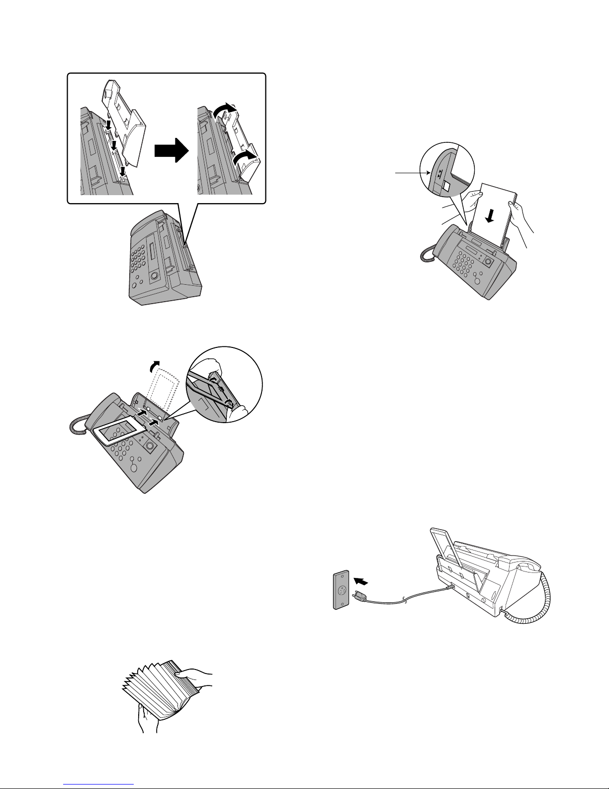
• Make sure the machine’s power cord is plugged in and paper is
laded before installing or replacing the print cartridge.
• If a document is inserted in the feeder, remove the document
before installing or replacing the print cartridge.
1) Press .
• Make sure the handset is on its cradle. If the handset is not on
the cradle, pressing will have no effect.
• The print cartridge holder moves to the cartridge replacement
position.
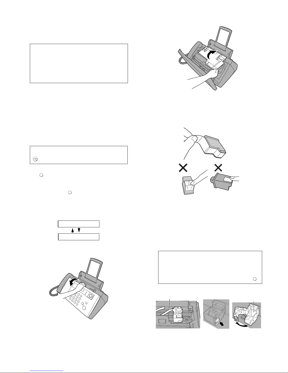
2) Open the operation panel.
3) Open the print compartment cover.
4) Remove only the tape from the new cartridge.
•Important: Make sure you remove all of the tape.
•CAUTION! DO NOT touch the gold contact area on the car-
tridge.
5) Make sure the cartridge holder has moved slightly away from the
right side of the compartment, and then pull the green lever and
open the cartridge holder cover.
• If you are replacing the cartridge, remove the old cartridge. If
you are going to use the old cartridge again, place it in an air-
tight container.
•CAUTION! DO NOT touch the contact area inside the cartridge
holder, or pull on the cable that is connected to the cartridge
holder.
Note: if the print compartment cover is left open for
approximately 30 minutes with a cartridge installed,
the cartridge will automatically return to its home
position. To make the cartridge return to the cartridge
replacement position when this has happened, press .
Print cartridge yield (at 4% coverage)
Initial cartridge
Quality mode OFF: Approx. 300 letter pages
Quality mode ON: Approx. 200 letter pages
Replacement cartridge (SHARP UX-C70B)
Quality mode OFF: Approx. 600 letter pages
Quality mode ON: Approx. 400 letter pages
Quality mode is initially turned on. To turn off Quality mode, see page 1-8.
If PRINTER ERROR or PRINTER ERROR/CHECK PAPER appears...
In the event that the display shows either of the above messages, you must clear the
error before installing the print cartridge. The error can usually be cleared by pressing
, or if a paper jam has occurred, by removing the paper jam.
INK
INK
Display:
PRESS INK KEY
REPLACE INK &
INK
Gold contact area
Cable

UX-B20U/UX-B20C/B25C
1 – 7
6) Insert the new print cartridge into the cartridge holder.
7) Place your index finger on the tab as shown and close the cartridge
holder cover with your thumb. Make sure the cover clicks into
place.
8) Close the print compartment cover.
9) Close the operation panel, pressing down firmly to make sure it
clicks into place.
10)Press to make the print cartridge holder return to its home
position.
11)Press (NEW) if the cartridge you installed is new.
Press (OLD) if the cartridge you installed is old.
12)Press .
If you selected “OLD” in the previous step, this completes the
installation procedure. (Note: If you find that print quality is not sat-
isfactory after reinstalling the old cartridge, align the cartridge as
explained.)
If you selected “NEW”, the display will show the alternating mes-
sages at right. Continue with the following steps to align the print
cartridge.
13)Press to print an alignment page. (To enter an alignment
value without printing an alignment page, press .)
14)In the alignment page that the machine prints, locate the line that
comes closest to forming a completely straight line.
Display:
PRESS INK KEY
REPLACE INK &
INK
1=NEW, 2=OLD
CHANGE CARTRIDGE
Display when "NEW" is
selected:
OK: PRESS START
NEW CART. OK?
START/
MEMORY
1=PRINT,2=SET
ALIGN CARTRIDGE
Display when "NEW" is
selected:
In
t
h
i
s
e
x
a
m
p
l
e
,
"
1
5
"
c
o
m
e
s
c
l
o
s
e
s
t
t
o
f
o
ff
r
m
i
n
g
a
s
t
r
a
i
g
h
t
l
i
n
e
.
E
N
T
E
R
(
0
-
3
0
)
1
5
A
f
t
f
f
e
r
t
h
e
a
l
i
g
n
m
e
n
t
p
a
g
e
i
s
p
r
i
n
t
e
d
,
t
h
e
d
i
sp
l
a
y
s
h
o
w
s
:

UX-B20U/UX-B20C/B25C
1 – 8
15)Press the number keys to enter the number of the straightest line.
Example:
• If you make a mistake, press and then repeat the entry.
16)Press .
• This completes the alignment procedure.
8. Setting the paper size
The machine has been set at the factory to scale received faxes to let-
ter size paper. If you loaded legal paper, you must change the paper
size setting to LEGAL.
9. Quality mode (using more/less ink)
If you prefer a higher quality image when printing faxes and copies,
turn on Quality mode. If you wish to use less ink or speed up ink drying
time, turn off Quality mode.
• Quality mode is initially turned on.
10. High-quality fax print setting (fast/slow printing
of faxes)
The high-quality fax print setting controls the speed at which faxes are
printed. If you prefer a higher quality image at a slower printing speed,
turn on this setting. If you prefer a faster printing speed over image
quality, turn off the setting.
Note: This setting only affects the printing speed. It does not affect the
amount of ink used.
• The high-quality fax print setting is initially turned off.
11. Connecting the telephone line cord
Insert one end of the line cord into the jack on the back of the machine
marked TEL. LINE. Insert the other end into a standard (RJ11C) sin-
gle-line wall telephone jack.
START/
MEMORY
1
Press once and twice.
2
Press once and once.
3
Press once.
4
Select the paper size:
LETTER: LEGAL:
5
Press to return to the date and time display.
The display briefly shows
your selection, then:
PAPER SIZE SET
COPY CUT-OFF
1=LETTER,2=LEGAL
Display:
PRINT SET-UP
Note: If at any time the display shows the alternating
messages at right, check the printing paper. If the tray is
empty, add paper. If there is paper in the tray, take it out
and then reinsert it. When you are finished, press
.
START/
MEMORY
ADD PAPER &
PRESS START KEY
1
Press once and twice.
2
Press once and 3 times.
3
Press once.
4
Press to turn on Quality mode, or
toturnitoff.
5
Press to return to the date and time display.
HQ FAX PRINT
The display briefly shows
your selection, then:
QUALITY MODE
1=YES, 2=NO
Display:
PRINT SET-UP
1
Press once and twice.
2
Press once and 4 times.
3
Press once.
4
Press to turn on high-quality fax
print, or to turn it off.
5
Press to return to the date and time display.
HQ COPY
The display briefly shows
your selection, then:
1=YES, 2=NO
HQ FAX PRINT
Display:
PRINT SET-UP
Setting the dial mode
The fax machine is set for tone dialing. If you are on a pulse dial line, you must
set the fax machine for pulse dialing. Press the panel keys as follows:
1
Press once and 3 times.
2
Press once and 3 times.
3
Press once.
4
Select the dial mode:
TONE: PULSE:
5
Press to exit.
Display:
The display briefly shows
your selection, then:
OPTION SETTING
DIAL MODE
DISTINCTIVE
1=TONE, 2=PULSE

UX-B20U/UX-B20C/B25C
1 – 9
12. Clearing a jammed document
If the original document doesn’t feed properly during transmission or
copying, or DOCUMENT JAMMED appears in the display, first try
pressing the START/MEMORY key. If the document doesn’t feed out,
remove it as explained below.
Important:
Do not try to remove a jammed document without releasing it as
explained below. This may damage the feeder mechanism.
1) Open the operation panel.
2) Gently and remove the document.
• Be careful not to tear the document.
3) Close the operation panel, pressing down firmly to make sure it
clicks into place.
13. Clearing jammed printing paper
Gently pull the jammed paper out of the machine, taking care not to
tear it. After removing the jammed paper, press to clear the
error message (PAPER JAMMED) from the display.
• Normal operation cannot be resumed until you press to clear
the error message.

UX-B20U/UX-B20C/B25C
1 – 10
[5] Quick setup guide
Plug the power cord into a
120-V grounded outlet.
Connect the phone line cord to the
TEL. LINE jack and a wall jack.
1
4
IMPORTANT!!
Should you require any
assistance setting up or
operating your product,
please
DO NOT RETURN YOUR
PRODUCT TO THE
STORE.
After referring to the setup guide
and operation manual, if you still
require assistance please
consult our web page at
www.sharpusa.com. From our
web page you will be able to
directly e-mail our customer
support team.
If you would like personal
assistance, please call our
Customer Assistance Center at
1-877-794-8675.
Connect the handset.
3
Load paper.
Note: If you are loading legal paper, see
of the operation manual to change the
paper size setting to LEGAL.
1. Open the
operation panel.
3. Remove the
packing tape.
4. Close the print
compartment cover.
Do not force
paper down into
the feed slot
The stack should
not be higher
than this line
1. Fan the paper.
56
7
Install the Print Cartridge.
2. Open the
operation panel.
4. Remove only the tape from the
new cartridge.
IMPORTANT:Makesureyou
remove all of the tape.
3. Open the print
compartment cover.
5. Make sure the cartridge holder has moved slightly away
from the right side of the compartment, and then pull the
green lever and open the cartridge holder cover.
Do not pull on the cable or touch the gold contact area.
7. Place your index finger on the tab and close
the cartridge holder cover with your thumb.
Caution! Do not touch
the gold contact area.
8. Close the print compartment cover
and then the operation panel.
10.a. Press to select NEW.
b. Press
c. Press to print an alignment page.
START/
MEMORY
11.In the alignment page that the machine
prints, locate the line that comes closest
to forming a completely straight line.
Enter the number of that line.
Example:
(If you make a mistake, press and
then repeat the entry.)
12. Press .
START/
MEMORY
1=PRINT,2=SET
ALIGN CARTRIDGE
6. Insert the new print cartridge
into the cartridge holder.
Note: To enter your name and fax number and set the date and time so that they
appear at the top of each fax you send, see page Chapter 1 of your operation manual.
Cable
Display:
1=NEW, 2=OLD
CHANGE CARTRIDGE
Gold contact area
2. Open the print
compartment cover.
5. Close the
operation panel.
Click!
If the tabs do not go into the
holes, turn the extension over.
2. Gently insert paper into the paper tray,
printsideup
..
1. Make sure the
handset is on its
cradle and then
press .
The cartridge
holder moves to
the cartridge
replacement
position.
INK
9. Press to make the cartridge
holder return to its home position.
INK
1. Attach the paper tray. 2. Attach the paper tray
extension.
Insert horizontally
and rotate up
2

UX-B20U/UX-B20C/B25C
1 – 11
[6] Quick reference guide
1. Sending Faxes
Place your document (up to 10 pages) face down in the document
feeder.
1.1. Normal Dialing
1. Lift the handset or press .
2. Dial the fax number.
3. Wait for the reception tone (if a person answers, ask them to press
their Start key).
4. Press .
1.2. Automatic Dialing
1. Press or until the desired destination appears in the
display.
2. Press .
1.3. Direct Keypad Dialing
1. Dial the fax number.
2. Press .
2. Receiving Faxes
Press the until the arrow in the display points to the desired
reception mode.
FAX mode: The fax machine automatically answers and receives
faxes.
TEL mode: Answer all calls (even faxes) by picking up the handset. To
begin fax reception, press .
3. Storing Auto Dial Numbers
1. Press once and twice.
2. Enter the full fax number.
3. Press .
4. Enter a name by pressing number keys. (To enter two letters in
succession that require the same key, press after entering
the first letter.)
5. Press and then .
START/
MEMORY
START/
MEMORY
START/
MEMORY
RESOLUTION/
RECEPTION
FAX
TEL
JAN-03 10:30
FAX
TEL
JAN-03 10:30
RESOLUTION/
RECEPTION
START/
MEMORY
START/
MEMORY
A=
B=
C=
D=
E=
F=
G=
H=
I=
J=
K=
L=
M=
N=
O=
P=
Q=
R=
S=
T=
U=
V=
W=
X=
Y=
Z=
SPACE =
START/
MEMORY

UX-B20U/UX-B20C/B25C
2 – 1
FAXUX-B20U/UX-B20C/B25CService ManualService ManualMarketE
CHAPTER 2. ADJUSTMENTS
[1] Adjustments
1. General
Since the following adjustments and settings are provided for this
model, make adjustments and/or setup as necessary.
2. Adjustments of output voltage (FACTORY ONLY)
1. Install the power supply unit in the machine.
2. Set the recording paper and document.
3. When the document is loaded, power is supplied to the output
lines. Confirm that outputs are within the limits below.
2.1. Output voltage settings
3. IC protectors replacement
ICPs (IC Protectors) are installed to protect the motor driver circuit.
ICPs protect various ICs and electronic circuits from an overcurrent
condition.
The location of ICPs are shown below:
1) FU100 (KAB5002) is installed in order to protect IC's from an
overcurrent generated in the motor drive circuit. If FU100 is open,
replace it with a new one.
2) FU101 (KAB3202) is installed in order to protect IC's from an
overcurrent generated in the motor drive circuit. If FU101 is open,
replace it with a new one.
4. Settings
4.1. Dial mode selector
DIAL mode (Soft Switch No. SW-B4 Data No. 3)
5. Volume adjustments
You can adjust the volume of the speaker, handset, and ringer using
the UP and DOWN arrow keys.
5.1. Speaker
5.2. Handset
5.3. Ringer
Output Voltage limits
+5V 4.75V ~ 5.25V
+30V 27.0V ~ 33.0V
1 +30V
2 +30V
3MG
4MG
5DG
6DG
Connector
No. CNPW
Pin No.
7
8
+5V
+5V
CNPW
CNCRMT
CNFDMT
CNHEAD1
CNHEAD2 CNPN
CNBKL
CONTROL PWB
CNSP CNCIS
CNPRG
CNLIU
CNLIU
18
CNPW
POWER SUPPLY PWB
LIU PWB
81
CNBKL
FU100
FU101
CNPW
CNCRMT
CNFDMT
CNHEAD1
CNHEAD2
CNPN
CNBKL
CONTROL PWB
(TOP SIDE)
CNSP CNCIS
CNPRG CNLIU
(step 1) Select "OPTION SETTING".
KEY : FUNCTION
DISPLAY: OPTION SETTING FINE PRIORITY
(step 2) Select "DIAL MODE".
KEY: Push until DIAL MODE is
indicated because the number of
's changes by the model.
DISPLAY: DIAL MODE 1=TONE, 2=PULSE
(step 3) Select, using "1" or "2".
KEY: 1
DISPLAY: TONE SELECTED
KEY: 2
DISPLAY: PULSE SELECTED
(step 4) End, using the "STOP" key.
KEY:
1
Press .
2
Press or to select the
desired volume le vel.
•Press again to turn off the speaker.
Display:
SPEAKER: HIGH
SPEAKER: MIDDLE
SPEAKER: LOW
1
Press or to select the
desired volume le vel.
(Make sure has not been pressed,
the handset is not lifted, and a
document is not loaded in the feeder.)
•The ringer will ring once at the selected
level.
2
If you selected RINGER: OFF OK ? to
turn off the ringer , press .
START/
MEMORY
Display:
RINGER: HIGH
RINGER: MIDDLE
RINGER: LOW
RINGER: OFF OK ?
1
When talking thr ough the handset,
press or to select the
desired volume le vel.
•
Note: The volume reverts to MIDDLE
each time you replace the handset.
Display:
RECEIVER: HIGH
RECEIVER: MIDDLE
RECEIVER: LOW

UX-B20U/UX-B20C/B25C
2 – 2
[2] Diagnostics and service soft switch
1. Entering the diagnostic mode
2. Diagnostic items
ITEM No. Contents Function
1 SOFT SWITCH MODE Soft switches are displayed and changed. List can be output.
2 ROM & RAM CHECK ROM sum-check and RAM is matched. Result list is output.
3 AGING MODE 10 sheets of check patterns are output every 5 minutes per sheet.
4 PANEL KEY TEST Panel keys are tested. Result list is output.
5 CHECK PATTERN Check pattern is output.
6 SIGNAL SEND MODE Various signals of FAX communication are output.
7 MEMORY CLEAR Back-up memory is cleared, and is set at delivery.
8 SHADING MODE Shading compensation is performed in this mode.
9 AUTO FEEDER MODE Insertion and discharge of document are tested.
10 ENTRY DATA SEND Registered content is sent.
11 ENTRY DATA RECEIVE Registered content is received, and its list is output.
Press FUNC →9→ → 8→#→7 , and the following display will appear.
ROM Ver. TC25 or TC44 After 2 sec: DIAG MODE
TC25 (UX-B20U)
TC44 (UX-B20C/UX-B25C)
Then press the START key. Select the desired item with the UP key or the DOWN key or select with the rapid key. Enter the mode with the
START key.
(Diag· specifications)
If the diag mode cannot be set, repeat the diag mode operation, per-
forming the following operation.
After the power is turned on and "WAIT A MOMENT" is indicated, press
the STOP key.
In relation with the process response (request from Production Engi-
neering) "WAIT A MOMENT" clock indication may appear depending on
STOP key timing. If the STOP key is held down, "MEMORY CLEAR?"
appears.
+
"Power ON"
FUNC DIAG MODE
9 8 7
STARTSoft switch mode
START
TC25 or TC44
STARTROM & RAM check
STARTAging mode
STARTPanel key test
STARTCheck pattern
STARTSignal send mode
START
START
START
START
START
Entry data rcv.
Entry data send
Auto feeder mode
Shading mode
Memory clear
START
KEY
STOP
KEY
START/
MEMORY

UX-B20U/UX-B20C/B25C
2 – 3
3. Diagnostic items description
3.1. Soft switch mode
Used to change the soft switch settings.
The soft switch which is stored internally is set by using the keys.
The available soft switches are SW-A1 to SW-P7.
The content of soft switches is shown in Soft switch description.
The contents are set to factory default settings.
3.2. ROM & RAM check
ROM executes the sum check, and RAM executes the matching test.
The result will be notified with the number of short sounds of the
buzzer as well as by printing the ROM & RAM check list.
Number of short sounds of buzzer 0 →No error
1 →FAX engine ROM error
2 →RAM error
(4Kbytes SRAM or 512Kbytes DRAM)
3.3. Aging mode
The check pattern will be printed sheet by sheet. This operation will be
executed at a rate of one sheet per 5 minutes, and will be ended at a
total of 10 sheets.
3.4. Panel key test
This mode is used to check whether each key operates properly.
Press the key on the operation panel, and the key will be displayed on
the LCD. Therefore, press all keys. At this time, finally press the STOP
key. When the STOP key is pressed, the keys that are not judged as
"pressed" will be printed on the result list.
• LED part of the contact image sensor (CIS) is kept on during the
term from when "START" of the panel test mode to end with the
STOP key.
3.5. Check pattern
Check patterns are printed on one sheet. Printing performance:The
following 4 items are checked.
• Print area:Checks that the print area is reserved.
• Nozzles:When checking the nozzle, make sure at least 1 line is
printed in each block: all the blocks of horizontal black bars and the
black line patterns in (B) and (C) ((B):16 patterns, (C):13 patterns).
(Note: If the nozzle (A) is not spraying properly, checking the area
(B) and (C) may be difficult (or may not be printed at all). In this
case, print again.
• Vertical align:Checks that the straight vertical line is drawn instead
of crooked line.
• Skew:Checks the skew of the recording paper.
Detailed of check patterns
(1)Top skew (2)Nozzle test (3)Vertical lines (4)Bottom skew
(5)Top margin (6)Left margin (7)Bottom margin
3.6. Signal send mode
This mode is used to send various signals to the circuit during FAX
communication. Every push of START key sends a signal in the follow-
ing sequence. Moreover, the signal sound is also output to the speaker
when the line monitor of the soft switch is on.
[1] No signals
[2] 9600BPS (V.29)
[3] 7200BPS (V.29)
[4] 4800BPS (V.27ter)
[5] 2400BPS (V.27ter)
[6] 300BPS (FLAG)
[7] 2100Hz (CED)
[8] 1100Hz (CNG)
3.7. Memory clear
This mode is used to clear the backup memory and reset to the default
settings.
3.8. Shading mode
The mode is used for the shading compensation. For reading, set up
the special original paper. (Refer to page 8-3)
The compensation memorizes the reference data of white and black
for reading.
Moreover, the memorized data is not erased even if memory clear
mode is executed.
3.9. Auto feeder mode
In this mode, a document is inserted and discharged to check the auto
feed function.
After this mode is started, set a document, and the document feed will
be automatically tested.
3.10. Entry data send
This mode is used to send the registered data to another machine and
make the other machine copy the registered content.
Before sending in this mode, it is necessary to set the other machine
at the entry data receive mode.
The following, information will be sent to the remote machine:
1. Telephone list data
2. Sender register data
3. Optional setting content
4. Soft switch content
5. Junk fax number
6. Recording setting list data
3.11. Entry data receive
In this mode, the registered data sent from the other machine is receiv-
ed and the received data is registered in the machine. When this mode
is used for receiving, the other machine must be in the entry data send
mode.
After receiving is completed, the following lists are printed.
1. Telephone list data
2. Sender register list (*)
3. Optional setting list (*)
4. Soft switch content
5. Junk fax number list (*)
6. Recording setting list data (*)
(*): Refer to SETUP LIST
0 1 2 3 4 5 6 7 8 9 10 11 12 13 14 15 16 17 18 19 20 21 22 23 24 25 26 27 28 29 30
(7)
(5)
(A)
(B)
(C)
(6) (1)
(2)
(3)
(4)

UX-B20U/UX-B20C/B25C
2 – 4
4. Entering the printer diagnostic mode
5. Printer diagnostic items
6. Printer diagnostic items description
6.1. 4% data print aging
This mode is the aging mode that prints the text pattern of 4%
6.2. ASF aging (all white)
This mode is the aging mode that tests the performance of the ASF
function.
6.3. ASF skew check aging
This mode is the aging mode that tests the performance of the ASF
function.
Detailed of check patterns
1. Top skew
2. Bottom skew
3. Top margin
4. Bottom margin
6.4. Cross pattern
This mode prints the test pattern that tests the performance of the
printer.
6.5. Initial cartridge data setting
This mode makes the dot counter the setting for initial cartridge, and
this mode resets the following counter.
1. Replacement counter of the cartridge
2. Paper jam counter
Item No. Contents Function
1 4% DATA PRINT AGING 4% of printing data continue to be printed.
2 ASF AGING The feed of the paper is continued.
3 ASF SKEW CHECK AGING The frame pattern continues to be printed to check the inclination performance.
4 CROSS PATTERN The image data of the cross pattern to be printed.
5 INITIAL CARTRIDGE DATA SETTING It makes the dot counter the setting for the initial cartridge.
6 IJP LIST MODE The maintenance data is printed.
7 PRINTER ERROR CHECK MODE The cause of “PRINTER ERROR” message is displayed.
Press FUNC 9 8 # 6 , and the following display will appear.
PRINT DIAG MODE
Then press the START key. Select the desired item with the up key or the down key or select with the rapid key. Enter the mode with the START key.
(Diag· specifications)
If the diagnostic mode cannot be set, repeat the diagnostic mode operation, performing the following operation.
After the power is turned on and "WAIT A MOMENT" is indicated, press the STOP key.
In relation with the process response (request from Production
Engineering) "WAIT A MOMENT" clock indication may appear depending
on STOP key timing. If the STOP key is held down, "MEMORY CLEAR?"
appears.
FUNC
PRINT DIAG MODE
9 8 6
START4% DATA PRINT AGING
ASF AGING
ASF SKEW CHECK AGING
CROSS PATTERN
INITIAL CARTRIDGE DATA SETTING
START
START
KEY
STOP
KEY
+
"Power ON"
START
START
START
START
START
IJP LIST MODE
START
PRINTER ERROR CHECK MODE
START/
MEMORY

UX-B20U/UX-B20C/B25C
2 – 5
6.6. IJP list mode
Maintenance data of the printer is output.
[Details of maintenance data]
6.7. Printer error check mode
The cause of “PRINTER ERROR” message is displayed.
[Details of Display]
Item Clear timing Update timing
Dot counter At the replacement cartridge After printing
Page counter At the replacement cartridge After printing
Number of head cleaning (Wiping of cartridge) At the initial cartridge setting At the maintenance
Replacement counter of the cartridge At the initial cartridge setting At the replacement of cartridge
Jam counter At the initial cartridge setting At every paper jam
Display Cause of “PRINTER ERROR” message
PRINTER ERR 01 Power on reset response was not received from printer.
PRINTER ERR 02 Print data transfer from Printer interface ASIC to printer was not completed for 180 sec.
PRINTER ERR 03 Cap position check of the carrier is failed.
PRINTER ERR 04 Printing 1 page is not finished during 5 min.
PRINTER ERR 05 Carrier moving from cartridge change position to cap position is failed.
PRINTER ERR 06 Carrier moving to cartridge change position is failed.
PRINTER ERR 07 Cartridge replacement is failed.
PRINTER ERR 08 Cartridge ID check is failed.
PRINTER ERR 09 Carrier was not reached to cap position for 60 sec after last printed page was exited.
PRINTER ERR 10 Paper pick up is failed.
PRINTER ERR 20 Carrier stall error.
PRINTER ERR 21 Carrier stall error.
PRINTER ERR 22 Carrier stall error.
PRINTER ERR 23 Carrier stall error.
PRINTER ERR 24 Printer head short error.
PRINTER ERR 25 Printer head heater control is failed.
PRINTER ERR 26 Print start position setting is abnormal.

UX-B20U/UX-B20C/B25C
2 – 6
7. How to make soft switch setting
To enter the soft switch mode, press the following key entries in sequence.
Press FUNCTION 9 8 7 STARTSTART
Press FUNCTION key.
Press key.
Press key.
Bit1 - 8 are set.
Soft SW-A2 - SW-P7 are set.
S F T SW-A1 = 10000000
S F T SW-A2 = 00000000
S F T SW-P7 = 00000000
Press key during setting.
To finish the settings halfway between
SW-A1 and SW-P7, press the STOP
key. In this case, the setting being done
to the SW No. on display will be nullified
while settings done to the preceding
SW No. remain in effect.
The soft switch mode is terminated.
S F T SW-A1 = 00000000
START
DATA No. 1 2 3 4 5 6 7 8
When the COPY key is pressed, the
contents of soft switches are printed.

UX-B20U/UX-B20C/B25C
2 – 7
8. Soft switch description
8.1. Soft switch
SW
NO.
DATA
NO. ITEM Switch setting and function Initial setting Remarks
10U/C
SW
l
A1
1 Protect from echo No Yes 0
2 Forced 4800 BPS reception Yes No 0
3 Footer print Yes No 0
4 Length limitation of copy/send/
receive
No limit Copy/send: 60 cm
Receive: 1 m
0
5 CSI transmission No transmitted Transmitted 0
6 DIS receive acknowledgement dur-
ing G3
Twice NSF: Once
DIS: Twice
0
7 Non-modulated carrier for V29
transmission modem
Yes No 0
8 EOL detect timer 25sec 13sec 0
SW
I
A2
1
2
3
4
Modem speed No. 1 No.2 No. 3 No. 4
0
0
0
1
V.29 9600bps 0 0 0 1
V.29 7200bps 0 0 1 1
V.27ter 4800bps 0 0 1 0
V.27ter 2400bps 0 0 0 0
5 Sender’s information transmit No Yes 0
6 H2 mode No Yes 0
7 Communication error treatment in
RTN sending mode (reception)
No communication error Communication error 0
8 CNG transmission No Yes 0
SW
l
A3
1
2
CED tone signal interval 1000ms 750ms 500ms 75ms
0
0
No. 1 1 1 0 0
No. 2 1 0 1 0
3 MR coding No Yes 0
4Reserved 0
5Reserved 0
6Reserved 0
7Reserved 0
8Reserved 0
SW
l
A4
1
2
3
4
5
Signal transmission level 0
0
1
1
1
6 Protocol monitor (Error print) Printed at communication error Not printed 0
7 Protocol monitor Yes No 0
8 Line monitor Yes No 0
SW
l
A5
1
2
Digital line equalization setting
(Reception)
7.2km 0km
1
1
No. 1 1 0
No. 2 1 0
3
4
Digital line equalization setting
(Transmission)
7.2km 0km
0
0
No. 3 1 0
No. 4 1 0
5
6
Digital cable equalizer setting
(Reception for Caller ID)
7.2km 0km
0
0
No. 5 1 0
No. 6 1 0
7 Error criterion 10 ~ 20% 5 ~ 10 % 0
8 Anti junk fax check Yes No 1
Binary input
No.= 168421
12345
EX0 0111
eg. Signal transmission level is set to -7dBm.
Other manuals for UX-B20
1
This manual suits for next models
1
Table of contents
Other Sharp Fax Machine manuals

Sharp
Sharp UX-60 User manual

Sharp
Sharp UX-8 User manual

Sharp
Sharp UX-B800 User manual

Sharp
Sharp Image Sender FO-IS125N User manual

Sharp
Sharp UX-178 User manual

Sharp
Sharp UX-310 User manual

Sharp
Sharp FO-730 User manual

Sharp
Sharp FO-455 User manual

Sharp
Sharp FO-785 User manual

Sharp
Sharp FO-71 User manual

Sharp
Sharp FO-1450 User manual

Sharp
Sharp FO-B1600 User manual

Sharp
Sharp FO-780A User manual

Sharp
Sharp UX-108 User manual

Sharp
Sharp AR-FX11 User manual

Sharp
Sharp FO-2150CM User manual

Sharp
Sharp FO-CC500 User manual

Sharp
Sharp UX-A255U User manual

Sharp
Sharp UXB700E User manual

Sharp
Sharp UX-460 User manual