Sharp MX-FX11 User manual

SERVICE MANUAL
Parts marked with " " are important for maintaining the safety of the set. Be sure to replace these parts with
specified ones for maintaining the safety and performance of the set.
This document has been published to be used
for after sales service only.
The contents are subject to change without notice.
SHARP CORPORATION
[1] SPECIFICATIONS
1. FAX function . . . . . . . . . . . . . . . . . . . . . . . . . . . . . . . . . . . . . . . . . . . . . . . . . . . . . . . . 1-1
[2] FAX SOFTWARE SWITCH
1. List . . . . . . . . . . . . . . . . . . . . . . . . . . . . . . . . . . . . . . . . . . . . . . . . . . . . . . . . . . . . . . . 2-1
2. Fax software switch initial value list . . . . . . . . . . . . . . . . . . . . . . . . . . . . . . . . . . . . . 2-25
[3] TROUBLE CODE
1. Image send communication report code. . . . . . . . . . . . . . . . . . . . . . . . . . . . . . . . . . . 3-1
2. Dial tone . . . . . . . . . . . . . . . . . . . . . . . . . . . . . . . . . . . . . . . . . . . . . . . . . . . . . . . . . . .3-5
[4] ELECTRICAL SECTION
1. Block diagram . . . . . . . . . . . . . . . . . . . . . . . . . . . . . . . . . . . . . . . . . . . . . . . . . . . . . . . 4-1
2. Actual wiring chart. . . . . . . . . . . . . . . . . . . . . . . . . . . . . . . . . . . . . . . . . . . . . . . . . . . . 4-2
CODE: 00ZMXFX11/S1E
CONTENTS
MX-FX11
MODEL
DIGITAL FULL COLOR
MULTIFUNCTIONAL SYSTEM OPTION
FACSIMILE EXPANSION KIT

Symbols in this manual
The lists of symbols used in this manual are shown below.
The meaning of each symbol described in the table must be understood for proper servicing.
1. Symbols used for notes and
cautions
2. Symbols used in the work
contents
Symbol Meaning
CAUTION Indicates a general
caution item.
HIGH TEMP Be careful of a high
temperature in the
fusing section.
HIGH VOLTAGE Be careful of an electric
shock where a high
voltage is applied such
as the high voltage
PWB, the main charger,
and the process section.
DANGER Indicates danger.
HANDLE WITH
CARE
Indicates a part which
requires special care for
handling such as the
HDD, and the LSU.
INHIBIT Indicates inhibit.
NO
ELECTROSTATIC
CHARGE
Be careful to keep away
from static electricity.
(PWB's and electric
parts)
NO DUST,
FINGER PRINT,
DIRT, SCRATCH
Be careful not to touch
directly, such as the
optical section, the
photoconductor, and the
DV roller.
Also be careful not to
scratch.
NO SCRATCH
NO LIGHT Be careful not to expose
to light, such as the
photoconductor, and the
test chart.
NO SOLVENT Be careful not to use a
solvent in cleaning, etc.
NO DISASSEMLE Do not disassemble.
Not serviceable.
Example CCD unit.
OK/GOOD Indicates a correct
procedure or result in an
adjustment, etc.
NO GOOD Indicates a wrong
procedure or result in an
adjustment, etc.
NOTE Indicates a note.
IMPORTANT Indicates an important
item.
REFER Indicates a reference
page, etc.
NEW Indicates a new
technology, a new
method, or a new item.
EXAMPLE Indicates a description
using an example.
Symbol Meaning (Work content)
Adhesion Indicates that a seal, etc.
is attached.
Adjustment Indicates an adjustment.
Measure a
dimension or a
size.
Indicates that a
dimension or a length is
measured.
Apply grease Indicates that grease is
to be applied.
Apply conductive
grease
Indicates conductive
grease is applied.
Cleaning
(Dry)
Indicates clean with a
dry cloth.
Cleaning
(Wet)
Indicates clean with a
cloth dampened with
water.
Cleaning
(Alcohol)
Indicates clean with
alcohol.
Cleaning
(Blower)
Indicates cleaning is
done with a blower/
brush.
Symbol Meaning

3. Symbols used for kinds of parts
4. Symbols used for additional
descriptions
Cleaning
(Vacuum)
Indicates that cleaning is
performed with a
vacuum cleaner.
Cleaning
(Brush)
Indicates that cleaning is
performed with a brush.
Oil Indicates that oil is
applied to lubricate.
Apply powder. Indicates that setting
power is applied to the
photoconductor drum,
the transfer belt, etc.
Replace Indicates that a part is
replaced.
Check Indicates that a check
(replacement,
adjustment, cleaning) is
performed.
Cut Indicates that cutting is
performed.
Loosen Indicates that a screw is
loosened.
Connect Indicates that a
connector is connected.
Disconnect Indicates that a
connector is
disconnected.
Remove a
harness.
Indicates that a harness
is unsecured.
Attach a harness. Indicates that a harness
is secured.
Remove a clamp.
Attach a clamp.
Release a hook. Indicates that a hook is
released.
Fix a hook. Indicates that a hook is
fixed.
Disengage the
pawl.
Symbol Meaning (Work content)
Engage the pawl.
Screw lock Indicates that a screw is
secured with adhesive.
Unlock
Turn OFF the
power.
Disconnect the
power plug.
Symbol Meaning (Kinds of parts)
Maintenance
part
Indicates a part which is
replaced in a maintenance
procedure.
Consumable
part
Indicates a consumable
part such as a
photoconductor,
developer, a transfer belt,
etc.
Waste part Indicates a waste part
which is consumed but
excluded from the above
consumable parts. (A
roller, a seal, etc.)
Unit part Indicates a part which is
designated as a unit.
Included part Indicates a part which is
included in the package
Symbol Meaning
View from the
top
Indicates from which
angle the drawing is
viewed.
View from the
bottom
View from the
front
View from the
back
Symbol Meaning (Work content)

MX-FX11 SPECIFICATIONS 1 – 1
MX-FX11 Service Manual
[1] SPECIFICATIONS
1. FAX function
A. Transmission method
Transmission time Less than 3 sec (Super G3)
Less than 7 sec (G3 ECM)
Compression/expansion system MH, MR, MMR, JBIG (Fixed to ECM for MMR or JBIG.)
Modem speed 33.6kbps →2.4kbps automatic fallback
Resolution 8 x 3.85 line/mm, 8 x 7.7 line/mm, 8.15.4 line/mm, 16 x 15.4 line/mm (Standard memory is used for transmit/receive.)
Intercommunication G3/Super G3: Standard (V.34, V.17, V.33, V.29, V.27ter)
Communication line General telephone line (PSTN), ISDN (When TA is installed.) Private Branch Exchange (PBX)
ECM Yes

MX-FX11 FAX SOFTWARE SWITCH 2 – 1
MX-FX11 Service Manual
[2] FAX SOFTWARE SWITCH
1. List
*2: Not used in the MX-2310U.
*3: Not used in the MX-2610N/3110N/3610N.
Lines
SW
No.
Bit
No. Item SW selection and function System settings
1 1-8 Country code Control is performed according to the set country code.
The destination setting that is set in SIM66-2 as the image send function is
reflected.
The country code setting cannot be directly made from this SW.
SW
No.
Bit
No. Item SW selection and function System settings
2 1-4 Calling Make time (10PPS)
setting
Setting of make time when dialling at 10PPS.
Make time can be set from 29 to 44ms in 1ms increments by binary inputting N
over the range of 0 to 15 (N + 29ms).
Adjustment value
5-8 Calling Break time setting
(10PPS)
Setting of break time when dialling at 10PPS.
Break time can be set from 56 to 71ms by in 1ms increments binary inputting N
over the range of 0 to 15 (N + 56ms).
Adjustment value
3 1-4 Calling Minimum pause time
(10PPS) setting
Setting of minimum pause time when dialling at 10PPS.
Minimum pause time can be set from 800 to 950ms in 10ms increments by
binary inputting N over the range of 0 to 15 (N x 10ms + 800ms).
Adjustment value
5-8 Calling Minimum pause time
(20PPS) setting
Setting of minimum pause time when dialling at 20PPS.
Minimum pause time can be set from 450 to 600ms in 10ms increments by
binary inputting N over the range of 0 to 15 (N x 10ms + 450ms).
Functions only in China and Thailand.
Adjustment value
4 1-4 Calling Make time (20PPS)
setting
Setting of make time when dialing at 20PPS.
Make time can be set from 9 to 24ms by binary inputting N over the range of 0
to 15 (N + 9ms).
Functions only in China and Thailand.
Adjustment value
5-8 Calling Break time setting
(20PPS)
Setting of break time when dialing at 20PPS.
Break time can be set from 26 to 41ms by binary inputting N over the range of 0
to 15 (N + 26ms).
Functions only in China and Thailand.
Adjustment value
5 1-4 Calling Setting of DTMF send
level (high group)
This sets the send level of high area and low area DTMF signals in units of 1dB.
Setting can be made over the range of 0dB to 15dB in 1dB increments by
binary inputting.
Adjustment value
5-8 Not used
6 1-4 Calling Setting of DTMF send
level (low group)
High group - Low
group: level difference
This sets the difference between the DTMF signal high area level and low area
level in units of 0.5dB.
Setting can be made over the range of -2.0dB to 5.5dB in 0.5dB increments by
binary inputting.
High group - Low group
"0 0 0 0": -2.0dB "1 0 0 0": 2.0dB
"0 0 0 1": -1.5dB "1 0 0 1": 2.5dB
"0 0 1 0": -1.0dB "1 0 1 0": 3.0dB
"0 0 1 1": -0.5dB "1 0 1 1": 3.5dB
"0 1 0 0": 0.0dB "1 1 0 0": 4.0dB
"0 1 0 1": 0.5dB "1 1 0 1": 4.5dB
"0 1 1 0": 1.0dB "1 1 1 0": 5.0dB
"0 1 1 1": 1.5dB "1 1 1 1": 5.5dB
Adjustment value
5-8 Not used
7 1-8 Calling Setting of DTMF
minimum pause time
This sets the minimum pause time between DTMF signals when sending DTMF
signals.
Minimum pause time can be set by binary inputting N over the range of 0 to 255
(1ms x N).
Setting can be made over the range of 50ms to 255ms in 1ms increments by
binary inputting.
When SW15-3,4 are set to other than "MODEM fixed," the set value less than
54ms is considered as 54ms.
The initial value is reverted to if a value outside of the setting range is set.
Adjustment value

MX-FX11 FAX SOFTWARE SWITCH 2 – 2
8 1-5 Calling DTMF signal send time This sets the time that DTMF signals are sent when sending DTMF signals.
Send time can be set over the rage of 70 to 310ms in 10ms increments by
binary inputting N from 0 to 31 (110ms x N).
The initial value is reverted to if a value outside of the setting range is set.
Adjustment value
6, 7 Calling Dial call waiting time This sets the waiting time from the end of line connection to the start of dial call
at times of automatic dial calling.
"00": 3.5 seconds
"01": 4 seconds
"10": 5 seconds
"11": 6 seconds
This only functions when dial tone detection is OFF.
Adjustment value
8 Calling Line current detection
at times of dial calling
Setting to determine whether or not to call dial following detection of line current
during line connection at times of automatic dial calling.
"1": No
"0": Yes
In cases where the setting is "Yes" but no line current can be detected, dial is
not called but the busy re-call procedure is followed.
Setting
9 1 Calling Manual calibration
setting when sending
Setting to execute the manual calibration or not when sending.
In case of an abnormal current waveform, the auto calibration fails and the
DTFM signal is deformed. This setting provides the countermeasure against
that problem.
"0": Execute
"1": Not execute
Setting
2 Call arrival Manual calibration
setting when a signal
arrives
Setting to execute the manual calibration or not when a signal arrives.
In case of an abnormal current waveform, the auto calibration fails and the
transmission is affected. This setting provides the countermeasure against that
problem.
"0": Execute
"1": Not execute
Setting
3-5 Not used
6 Calling No. 2 dial tone
detection
Setting of ON/OFF of No.2 dial tone detection function.
"0": OFF (No. 2 dial tone detection is not performed.)
"1": ON (No. 2 dial tone detection is performed.)
Setting
7 Calling Dial tone detection When the setting is "Yes," the dial is sent following confirmation of detection of
the dial tone when the line is captured; and when the setting is "No," dial is sent
without a dial tone because no confirmation of dial tone detection is carried out
after line capture.
"0": No
"1": Yes
Setting
8 Calling Dial tone ON detection
time (during
continuous detection)
This sets the waiting time from the end of line connection to the start of dial call
at times of automatic dial calling.
"0": 1.5 seconds
"1": 1 seconds
Adjustment value
10 1-4 Calling Lower limit of dial tone
ON/OFF detection time
(during intermittent
detection)
This sets the lower limit time for detection of dial tone ON/OFF time.
Setting can be made over the range of 40ms to 490ms in 30ms increments by
binary inputting.
(N x 30ms) + 40ms
This is only valid during intermittent DT detection.
Adjustment value
5-8 Calling Upper limit of dial tone
ON/OFF detection time
(during intermittent
detection)
This sets the upper limit time for detection of dial tone ON/OFF time.
Setting can be made over the range of 400ms to 1900ms in 100ms increments
by binary inputting.
(N x 100ms) + 400ms
This is only valid during intermittent DT detection.
Adjustment value
11 1-4 Calling External line
connection number
setting 1 <First digit>
When No. 2 dial tone is detected, this area is compared with the external in
connection number. If they match, the units waits for No. 2 dial tone.
Up to two external line connection numbers (max. 4 digits) can be registered as
options.
The first digit of the external line connection number 1 is set.
The numbers and codes which can be registered are as follows.
0 - 9 / * (a) / # (b) / – (pause) (c) / Not used for this digit and after (d) /
Any is OK (f)
When set to [e], it is considered as setting to [0].
Setting
5-8 Calling External line
connection number
setting 1 <Second
digit>
The second digit of the external line connection number 1 is set.
The numbers and codes which can be registered are as follows.
0 - 9 / * (a) / # (b) / – (pause) (c) / Not used for this digit and after (d) /
Any is OK (f)
When set to [e], it is considered as setting to [0].
Setting
SW
No.
Bit
No. Item SW selection and function System settings

MX-FX11 FAX SOFTWARE SWITCH 2 – 3
12 1-4 Calling External line
connection number
setting 1 <Third digit>
The third digit of the external line connection number 1 is set.
The numbers and codes which can be registered are as follows.
0 - 9 / * (a) / # (b) / – (pause) (c) / Not used for this digit and after (d) /
Any is OK (f)
When set to [e], it is considered as setting to [0].
Setting
5-8 Calling External line
connection number
setting 1 <Fourth digit>
The fourth digit of the external line connection number 1 is set.
The numbers and codes which can be registered are as follows.
0 - 9 / * (a) / # (b) / – (pause) (c) / Not used for this digit and after (d) /
Any is OK (f)
When set to [e], it is considered as setting to [0].
Setting
13 1-4 Calling External line
connection number
setting 2 <First digit>
The first digit of the external line connection number 2 is set.
The numbers and codes which can be registered are as follows.
0 - 9 / * (a) / # (b) / – (pause) (c) / Not used for this digit and after (d) /
Any is OK (f)
When set to [e], it is considered as setting to [0].
Setting
5-8 Calling External line
connection number
setting 2 <Second
digit>
The second digit of the external line connection number 2 is set.
The numbers and codes which can be registered are as follows.
0 - 9 / * (a) / # (b) / – (pause) (c) / Not used for this digit and after (d) /
Any is OK (f)
When set to [e], it is considered as setting to [0].
Setting
14 1-4 Calling External line
connection number
setting 2 <Third digit>
The third digit of the external line connection number 2 is set.
The numbers and codes which can be registered are as follows.
0 - 9 / * (a) / # (b) / – (pause) (c) / Not used for this digit and after (d) /
Any is OK (f)
When set to [e], it is considered as setting to [0].
Setting
5-8 Calling External line
connection number
setting 2 <Fourth digit>
The fourth digit of the external line connection number 2 is set.
The numbers and codes which can be registered are as follows.
0 - 9 / * (a) / # (b) / – (pause) (c) / Not used for this digit and after (d) /
Any is OK (f)
When set to [e], it is considered as setting to [0].
Setting
15 1, 2 Calling DT/BT detection level This sets the minimum detection level for determining that dial tone and busy
tone have been detected. Signal levels not larger than this setting are ignored.
"00": -43dB
"01": -35dB
"10": -33dB
"11": -30dB
DT, BT common
Adjustment value
3, 4 Calling DT/BT detection
frequency range
setting
This sets the detection frequency range when detecting dial tone and busy
tone.
Change the setting if dial tone and busy tone are erroneously detected.
"00": MODEM fixed (about 308Hz - 517Hz)
"01": 420Hz - 680Hz
"10": 360Hz - 440Hz
"11": 245Hz - 650Hz
For CTR21: 245Hz - 650Hz
Adjustment value
5 Calling Busy tone detection Setting to determine whether or not to detect the busy tone signal during
automatic dial calling and when the external telephone simulated call sound is
ringing.
"0": Detect
"1": Do not detect
Setting
6 Calling Busy tone OFF non-
detection time
This sets the non-detection time on the busy tone OFF section.
Change the setting in cases where noise, etc. on the busy tone ON section
adversely affects the ON section.
"0": 100ms
"1": 300ms
* Make shorter than the "busy tone OFF detection time."
Adjustment value
7, 8 Calling Lower limit of busy
tone ON detection time
This sets the lower limit time of the ON section when detecting frequency of the
busy tone signal.
If busy tone signals are not detected in excess of this time, do not count as 1
pulse.
"00": 250ms
"01": 140ms
"10": 450ms
"11": 350ms
Adjustment value
SW
No.
Bit
No. Item SW selection and function System settings

MX-FX11 FAX SOFTWARE SWITCH 2 – 4
16 1, 2 Calling Upper limit of busy
tone ON detection time
This sets the upper limit time of the ON section when detecting frequency of the
busy tone signal.
If busy tone signal is detected in excess of this time, do not count as 1 pulse.
"00": 750ms
"01": 650ms
"10": 1000ms
"11": 2850ms
Adjustment value
3, 4 Calling Lower limit of busy
tone OFF detection
time
This sets the lower limit time of the OFF section when detecting frequency of
the busy tone signal.
If busy tone OFF signals are not detected in excess of this time, do not count as
1 pulse.
"00": 250ms
"01": 140ms
"10": 450ms
"11": 350ms
Adjustment value
5, 6 Calling Upper limit of busy
tone OFF detection
time
This sets the upper limit time of the OFF section when detecting frequency of
the busy tone signal.
If busy tone signal is detected in excess of this time, do not count as 1 pulse.
"00": 750ms
"01": 650ms
"10": 1000ms
"11": 2850ms
Adjustment value
7, 8 Not used
17 1-4 Call arrival Call signal OFF non-
detection time
This sets the time for ignoring OFF signals and regarding ON time to be
continuous following ON detection of the call signal (CI).
This is intended to treat the PBX call signal "ring-ring" as a single call signal.
Setting can be made over the range of 0ms to 1500ms in 100ms increments by
binary inputting.
Adjustment value
5-8 Call arrival Lower limit of call
signal ON time
This sets the minimum ON time for detecting call signal (CI) pulses (number of
pulses). 1 pulse is counted if the CI signal remains ON for the set ON time or
longer.
Setting can be made over the range of 150ms to 300ms in 10ms increments by
binary inputting.
Adjustment value
18 1-4 Call arrival Upper limit of call
signal ON time
This sets the maximum ON time for detecting call signal (CI) pulses (number of
pulses). Disregard and do not count as 1 pulse if the CI signal remains ON for
the set ON time or longer.
Setting can be made over the range of 3000ms to 4500ms in 100ms
increments by binary inputting.
Adjustment value
5-8 Call arrival Lower limit of call
signal OFF time
This sets the minimum OFF time for detecting call signal (CI) pulses (number of
pulses). 1 pulse is counted if the CI signal remains OFF for the set OFF time or
longer.
Setting can be made over the range of 100ms to 1500ms in 100ms increments
by binary inputting.
Setting range
When 0 is set, initial value 700ms operation takes place.
Adjustment value
19 1, 2 Call arrival Upper limit of call
signal OFF time
This sets the maximum waiting time from detection of the call signal (CI) pulse
(number of pulses) to detection of the next CI signal pulse.
Accordingly, if the next CI signal pulse is not detected within this time, the
number of calls up to now is cleared.
"00": 6.5 seconds
"01": 10 seconds
"10": 15 seconds
"11": 20 seconds
Adjustment value
3 Call arrival CI clear judgment Setting of the judgment of CI signal 1 cycle.
"1": Cleared only when the max. cycle is exceeded. (The min. cycle is 0.)
"0": Cleared when outside the range of 1 cycle. (The min. and the max. cycles
are set with other soft switches.)
4, 5 Call arrival Filter time when the CI
signal is detected.
The detection sampling time of the CI signal is set in the CI signal detection
setting.
"00": 10ms
"01": 5ms
"10": 15ms
"11": 20ms
6-8 Not used
20
-
23
1-8 Not used
SW
No.
Bit
No. Item SW selection and function System settings

MX-FX11 FAX SOFTWARE SWITCH 2 – 5
Communications
SW
No.
Bit
No. Item SW selection and function System settings
24 1-8 Communication Signal sending level Set the level adjustment for sending signals from the modem. Setting can be
made over the range of 0 to 26 in 1dBm increments by binary inputting.
Since the maximum level differs according to country, if a value above the
maximum level is set, the maximum value for the present country code will be
adopted. (For North America and China, there is no limitation on the max. send
level.)
When set to a value greater than the upper limit, it is considered as setting to
the upper limit. When set to a value smaller than the lower limit, it is considered
as setting to the lower limit.
If, however, it is set to 27 to 255, it is considered as setting to 26.
Adjustment value
25 1-3 Transmission Setting of call time (T0
timer setting) in
automatic transmission
Setting to determine how many seconds to call when the other party doesn’t
respond at times of automatic transmission.
Setting can be made over the range of 30 to 60 (China: 30 to 45, Russia: 30 to
35) seconds in 15 (Russia: 5) second increments by binary inputting N ((15
(Russia: 5) seconds x N) + 30 seconds).
The initial value is reverted to if a value outside of the setting range is set.
Timer
4-7 Communication T1 timer setting Setting to determine how many seconds the line is connected when the other
party’s machine doesn’t respond to FAX communication.
Setting can be made over the range of 30 to 105 seconds in 5-second
increments by binary inputting ((5 seconds x N) + 30 seconds).
T1 timer is the timer used from the point where the other party’s machine
recognizes (CED or DCS) as FAX following line connection. 35±5 seconds
according to the ITU-T standard.
Timer
8 Not used
26 1, 2 Communication T2 timer setting The time until a command is received is set.
"00": 6 seconds
"01": 7 seconds
"10": 8 seconds
"11": 9 seconds
This is the timer for receiving a command such as the DIS signal. 6±1 seconds
in the ITU-T standards.
3, 4 Communication T4 timer setting
Timer during automatic
operation (+1.5
seconds at times of
manual operation)
This sets the timer for up until reception of the response.
+1.5 seconds at times of manual operation
"00": 3 seconds
"01": 4 seconds
"10": 5 seconds
"11": 6 seconds
This is the timer for up until reception of the response to the DCS signal, etc. 3
seconds ±15% under the ITU-T standard.
Timer
5 Reception EOL detection timer Setting to determine how many seconds to set the detection timer for EOL
(EndOfLine) during Phase-C reception in G3.
"0": Setting to 13 seconds
"1": Setting to 25 seconds
When error occurs in EOL detection, treat as non-detection of EOL.
Timer
6 Communication Sharp machine mode Setting is made whether Sharp's unique procedures (relay, confidential) are
allowed or not by not sending NSF/NSS/NSC and not confirming that the
machine is a Sharp machine or not.
"0": Check
"1": Not check
7, 8 Communication Modem lightning
protection measures
Function that corresponds to IEC lightning surge requirements as prescribed in
the European CE standard.
In cases where the machine cannot shift from CFR or MCF to high-speed
signals (image signals) due to lightning interference, this extends the MPS
waiting time.
"00": 0 second
"01": 20 seconds
"10": 30 seconds
"11": 40 seconds
Setting

MX-FX11 FAX SOFTWARE SWITCH 2 – 6
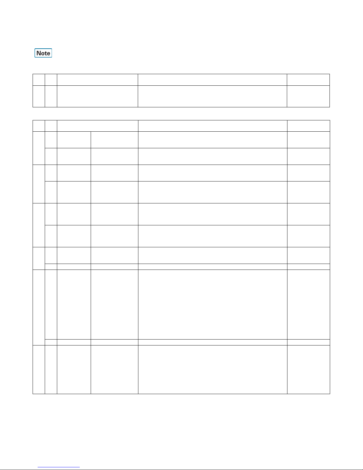
27 1, 2 Reception CED signal sending
time
This sets the time over which the CED signal is sent.
"00": 3 seconds
"01": 4 seconds
"10": 5 seconds
"11": No
Communication/
Adjustment value
3 Reception CED/ANSam detection
time
This sets the time up until determination of the signal when detecting CED/
ANSam signals.
"0": 500ms
"1": 1000ms
Adjustment value
4 Reception V.34 mode function (on
call arrival)
Setting to determine whether or not to make the V.34 mode valid as machine
capacity when receiving (on call arrival).
"0": V.34 valid
"1": V.34 invalid
Setting
5 Transmission V.34 mode function
(including polling when
calling)
Setting to determine whether or not to make the V.34 mode valid as machine
capacity when transmitting (calling and polling).
"0": V.34 valid
"1": V.34 invalid
Setting
6 Transmission V.34 mode function at
times of manual
communication
Setting to determine whether or not to make the V.34 mode valid at times of
manual communication (transmitting and receiving).
"0": V.34 valid
"1": V.34 invalid
However, in cases where the V.34 mode function (including polling when
calling) is set at 1: V.34 invalid, the V.34 mode will be rendered invalid even if
this SW is set to 0: valid.
Communication/
Setting
7 Transmission 3429 symbol rate
transmission enable
during V.34
transmission.
Setting to determine whether or not to enable 3429Hz as the symbol rate for
V.34.
When this is at "disable," 3429Hz is not selected.
However, only valid during transmission.
"0": disable
"1": enable
Setting
8 Transmission Symbol rate 3200 high
carrier transmission
enable during V.34
transmission
When 3200Hz is selected as the V.34 symbol rate, there are Low/High carriers,
but this setting determines whether or not both can be used.
When this is at "disable," 3200 High is not selected.
However, only valid during transmission.
When both Low/High are at "disable," SymbolRate=3200Hz is not selected.
"0": disable
"1": enable
Setting
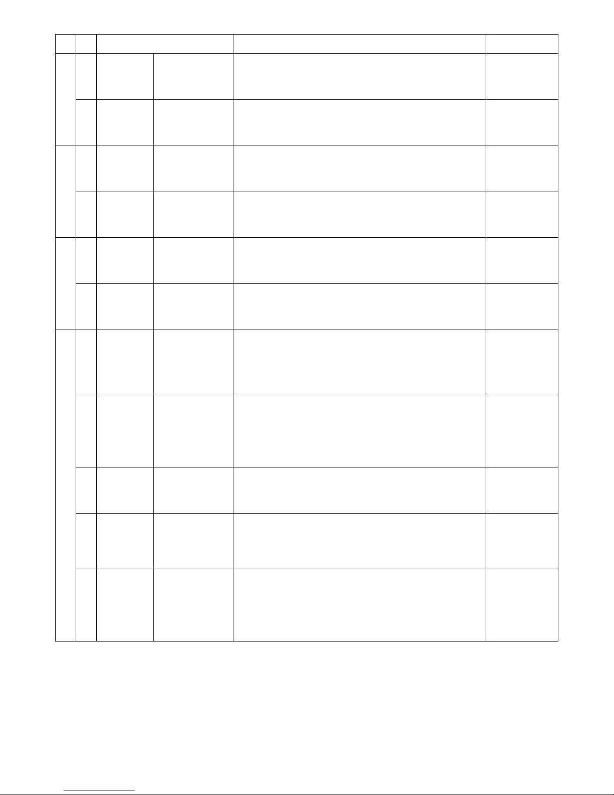
28 1 Transmission Symbol rate 3200 low
carrier transmission
enable during V.34
transmission
When 3200Hz is selected as the V.34 symbol rate, there are Low/High carriers,
but this setting determines whether or not both can be used.
When this is at "disable," 3200 Low is not selected.
However, only valid during transmission.
"0": disable
"1": enable
Setting
2 Transmission Symbol rate 3000 high
carrier transmission
enable during V.34
transmission
When 3000Hz is selected as the V.34 symbol rate, there are Low/High carriers,
but this setting determines whether or not both can be used.
When this is at "disable," 3000 High is not selected.
However, only valid during transmission.
When both Low/High are at "disable," SymbolRate=3000Hz is not selected.
"0": disable
"1": enable
Setting
3 Transmission Symbol rate 3000 low
carrier transmission
enable during V.34
transmission
When 3000Hz is selected as the V.34 symbol rate, there are Low/High carriers,
but this setting determines whether or not both can be used.
When this is at "disable," 3000 Low is not selected.
However, only valid during transmission.
"0": disable
"1": enable
Setting
4 Transmission Symbol rate 3429
enable during V.34
transmission
Setting whether use of 3429Hz is enabled or not as the symbol rate in V.34
transmission.
When this is set to [Disable], 3429Hz cannot be selected.
"0": disable
"1": enable
5 Transmission Symbol rate 2800
enable during V.34
transmission
Setting to determine whether or not to enable 2800Hz as the symbol rate for
V.34.
When this is at "disable," 2800Hz is not selected.
"0": disable
"1": enable
Setting
6 Transmission Symbol rate 2743
enable during V.34
transmission
Setting to determine whether or not to enable 2743Hz as the symbol rate for
V.34.
When this is at "disable," 2743Hz is not selected.
"0": disable
"1": enable
Setting
SW
No.
Bit
No. Item SW selection and function System settings

MX-FX11 FAX SOFTWARE SWITCH 2 – 7
28 7, 8 Communication Coding capacity during
transmission and
reception (V.34
communication)
(reflected in DIS/DCS/
DTC)
This sets the coding capacity that is communicated to the other party’s machine
in V.34 communication.
"00": JBIG/MMR/MR/MH
"01": MMR/MR/MH
"10": MR/MH
"11": MH
Communication/
Setting
29 1, 2 Communication Coding capacity during
transmission and
reception (other than
V.34 communication)
(reflected in DIS/DCS/
DTC)
This sets the coding capacity that is communicated to the other party’s machine
in communication other than V.34.
"00": JBIG/MMR/MR/MH
"01": MMR/MR/MH
"10": MR/MH
"11": MH
Communication/
Setting
3-6 Transmission Modem transmission
speed (Other than
V.34) (DCS)
This sets the initial speed (upper limit) in transmission of other than V.34.
Reflect in DCS.
When the default setting is made, V.17 14400bps is notified to the other party’s
machine.
Communication does not always happen at this speed.
Speed/
Adjustment value
7, 8 Reception Fixing of modem
speed during reception
(Other than V.34) (DIS)
This sets the initial speed (upper limit) in transmission of other than V.34.
When the default setting is made, V.17 14400bps is notified to the other party’s
machine.
Communication does not always happen at this speed.
"00": Not fixed
"01": V.29-9600bps
"10": V.27ter-4800bps
"11": V.17-14400bps
Speed/
Setting
30 1-4 Reception V.34 Symbol Rate
Mask (when receiving)
This sets the symbol rate when receiving in the V.34 mode.
"0000": 2400
"0001": 2400
"0010": 2800/2400
"0011": 3000/2800/2400
"0100": 3200/3000/2800/2400
"0101": 3429/3200/3000/2800/2400
When set at a value other than those shown above, the initial value of "0101" is
activated.
Communication/
Setting
5 Transmission Echo countermeasure
(setting of hold time
between DIS reception
and sending of signal)
when transmitting.
Setting to determine how many seconds the interval is from receiving DIS to
sending the DCS signal. This is only valid for communications of other than
V.34.
"0": 500msec
"1": 800msec
Communication/
Setting
6 Reception Echo countermeasure
(CED tone sending
interval) when
receiving
Setting to determine how many seconds the interval is from sending CED or
ANSam to sending the DIS FSK signal.
"0": 75msec
"1": 500msec
Communication/
Setting
7 Transmission Confirmation of DIS
reception when
sending
Setting to determine how to confirm DIS reception when transmitting.
"0": Once for NFS reception, twice for DIS reception
"1": Twice
Valid apart from V.34
Communication/
Setting
8 Reception Enable/Disable of 33
bit or later of DIS
(Reflected only to DIS)
Setting whether DIS is limited to 32 bit or not when receiving FAX.
When limited, JBIG reception, F code reception, and UFN reception cannot be
made. However, sending is enabled as well as polling.
"0": Enable (33 bit or later enabled)
"1": Disable (33 bit or later disabled)
SW
No.
Bit
No. Item SW selection and function System settings
"0000": V.27ter 2400bps "1000": V.17 14400bps
"0001": V.29 9600bps "1001": V.17 9600bps
"0010": V.27ter 4800bps "1010": V.17 12000bps
"0011": V.29 7200bps "1011": V.17 7200bps
"0100": V.33 14400bps "1100": V.17 14400bps
"0101": V.17 14400bps "1101": V.17 14400bps
"0110": V.33 12000bps "1110": V.17 14400bps
"0111": V.17 14400bps "1111": V.17 14400bps

MX-FX11 FAX SOFTWARE SWITCH 2 – 8
31 1 Reception CSI sending Setting to determine whether or not to send the CSI signal.
The CSI signal contains the transmission source number.
"0": Yes (send the CSI signal)
"1": No (do not send the CSI signal)
Setting
2 Transmission Echo suppressor tone
setting No. 1
Setting to determine whether or not to have the echo suppressor tone in the
high-speed modulation mode.
"0": With V33
"1": Without V33
Setting
3 Transmission Echo suppressor tone
setting No. 2
Setting to determine whether or not to have the echo suppressor tone in the
high-speed modulation mode.
"0": With V17
"1": Without V17
Communication/
Setting
4 Transmission Echo suppressor tone
setting No. 3
Setting to determine whether or not to have the echo suppressor tone in the
high-speed modulation mode.
"0": With V29
"1": Without V29
Setting
5 Transmission Echo suppressor tone
setting No. 4
Setting to determine whether or not to have the echo suppressor tone in the
high-speed modulation mode.
"0": With V27
"1": Without V27
Communication/
Setting
6, 7 Reception Image capacity when
receiving
(Reflect in DIS, Do not
reflect in DTC.)
This sets the reception resolution capacity when FAX calls arrive (when
sending DIS).
Reflect in DIS, Do not reflect in DTC.
"00": Very fine
"01": Fine
"10": When small
"11": Ordinary lettering
Setting
8 Not used
32 1, 2 Reception Designation of
reception size
(indicating the width of
reception capacity)
This sets this machine’s receivable document width that is notified to the other
party’s machine when receiving.
"00": By loaded cassette
"01": A4 width
"10": B4 (A4, B4) width
"11": A3 (A4, B4, A3) width
When using the loaded cassette, width is as follows depending on the
maximum cassette size.
A5/5.5x8.5R size: A4 width
B5 size: B4 width
A4/8.5x11 size: A3 width
8.5x13/8.5x14: A3 width
B4 size: B4 width
11x17: B4/A3 width (changeover by means of the FAX soft SW)
A3 size: A3 width
A3 width is adopted in cases where a tray capable of receiving and printing
facsimiles is not set and cases where all cassettes are open.
Setting
3 Transmission Training Setting whether the training in high speed sending is set to long or short in
V.17.
"0": Short
"1": Long
4 Reception Reception gain
changeover when
receiving
Setting to determine the FTT determination method when confirming TCF
reception.
"0": Judge the EQM value to determine if the received data is 0
"1": Only judge from the EQM value. Accordingly, TCF confirmation becomes
loose
Communication/
Setting
5 Reception Time out time setting
after starting TCF
signal reception
The time for time out is set after starting TCF signal reception.
"0": 4 seconds
"1": 2 seconds
Setting
6 Communication Time between DCS-
TCF
Setting to determine how many seconds in the interval between DCS
transmission and sending of the TCF signal.
"0": 75msec
"1": 150msec
75±20ms in the ITU-T standard.
Adjustment value
7, 8 Communication 300bps preamble send
time
The preamble send time is set in the FSK signal sending.
"00": 0.5 seconds
"01": 1 second
"10": 1.5 seconds
"11": 2 seconds
SW
No.
Bit
No. Item SW selection and function System settings

MX-FX11 FAX SOFTWARE SWITCH 2 – 9
Functions
33 1, 2 Transmission Phase-C head dummy
data send time
Setting of the time to send the dummy data until sending the head data when
sending in Phase-C.
"00": 0.3 seconds
"01": 0.4 seconds
"10": 0.5 seconds
"11": 0.2 seconds
When the dummy data send time is increased, the remote machine which
receives data can easily detect high speed signals.
3 Communication Error handling when
transmission and
receiving RTN
Setting to determine whether or not to recognize communication errors when
receiving RTN signals (only in the V.17 mode).
"0": Recognize errors during RTN reception
"1": Do not recognize error during RTN reception
Setting
4, 5 Reception SED ON level when
receiving
Setting of an indication of the receivable level when receiving FAX signals.
When noises are picked up and PPR occurs frequently, set to "-43dBm" or
greater. (For example, "-38dBm.")
"00: -48dBm
"01: -38dBm
"10: -33dBm
"11: -43dBm
6, 7 Transmission Transmission cable
amplitude equalizer
When sending FAX signals, apply different gain from the frequency to the data
signals between the modem and line. Setting to determine how high to make
the 4000Hz gain compared to 0Hz.
"00": 0dB
"01": 4dB
"10": 8dB
"11": 12dB
Indispensable in Australia
Communication/
Adjustment value
8 Not used
34 1, 2 Reception Receive cable
amplitude equalizer
When FAX signals are received, a gain different from the frequency is applied
to the data signals between the MODEM and the line. Setting of how much
greater the gain of 4000Hz is set when compared with 0Hz.
"00": 0dB
"01": 4dB
"10": 8dB
"11": 12dB
3-8 Not used
35 1-8 Not used
SW
No.
Bit
No. Item SW selection and function System settings
SW
No.
Bit
No. Item SW selection and function System settings
36 1 Not used
2 Communication F.A.S.T function This sets the management function performed in the FAX communication
procedure through the telephone line.
"0": No
"1": Yes
Valid only in North America.
3 Print Print setting when
there is no
communication record
table data
Setting to determine whether the record table is printed or not in the list printing
from the system when there is no record data (history) which have not printed
in printing of the communication record table.
The list printing from the system setting is as follows:
• Print output by selecting from the data list print
• Time specification print from the FAX setting or print at memory full
"0": Do not print
→"No print data" is displayed and printing of a list is disabled.
"1": Print
→A list is printed though there is no new history.
This setting is used to check that there is no new history.
4 Print Report output (when
cancelled)
Setting to determine whether or not to output the communication results sheet
in cases where document transmission is cancelled while in progress.
"0": Do not output
"1": Output
5 Print Report output (when
refusing reception)
<FAX only>
Setting to determine whether or not to output the communication results sheet
when reception is refused in FAX reception. However, other than not printing is
set by means of the report output (when receiving) setting.
"0": Do not output
"1": Output
Internet FAX is set by means of SW63-2.
Irrespective of "Always print" and "Error," the results sheet is not printed.

MX-FX11 FAX SOFTWARE SWITCH 2 – 10
36 6 Print Printing of transmitted
document contents at
times of F code
communication
<FAX only>
Setting to determine whether or not to print part of the transmitted document on
the communication results sheet at times of F code communication. However,
only when the "Document contents printing at times of transmission" setting is
valid.
"0": Do not print
"1": Print
The "Document contents printing (results sheet) at times of transmission"
setting takes priority.
7 Print Document content print
when sending (PC-Fax
(Internet Fax) report
table)
Setting to print images or not on the report table when sending PC-Fax
(Internet Fax).
"0": Not print
"1": Print
When the system setting is set so that images are added in the communication
report table, if the destination is a PC-Fax (Internet Fax), the document
contents are printed by this setting.
8 Not used
37 1, 2 Function Protocol monitor Setting to determine whether or not the protocol monitor (recognized by the
FAX) for 1 communication is printed.
"00": No (do not print)
"01": No (do not print)
"10": Print (always)
"11": Only at times of error (print)
When a new communication occurs before the protocol monitor is printed,
delete the old protocol data (overwrite).
3 Function Determination of sub-
scan length
(determination setting
when selecting the
page)
Setting to determine whether to give priority to width or length when selecting
the optimum sheet when printing received data.
"0": Priority to data length
"1": Priority to data width
4 Print Paper selection when
reception printing
(LTR/A4)
Used to set whether LTR is confirmed first of all in selection of paper for
reception printing or paper that provides smaller reduction rate of A4 and LTR is
selected.
"0": Priority on LTR/A4 reduction rate
"1": Priority on LTR
5 Not used
6 Function Valid/Invalid setting of
FAX A4, 8.5 x 11
threshold
When printing received FAX data with A4 and 8.5 x 11 paper in the tray, this
setting determines whether to make threshold values in paper selection valid or
invalid. If made valid, it becomes easier to select letters.
"0": Valid
"1": Invalid
When printing received Internet FAX data, conduct setting using the separate
SW (Valid/Invalid setting of Internet FAX A4, 8.5 x 11 threshold).
7 Reception Setting of the reception
width of 11x17 sheet
This sets the receivable document width in cases where "11 x 17 sheet" is
selected as the FAX printing paper.
"0": A3 width (A3, B4, A4)
"1": B4 width (B4, A4)
8 Communication Data line parity check
(Between ICU -
FAXBOX)
The parity on the data line between the ICU and the FAXBOX is checked.
(Supporting the E7-06 problem)
"0": Parity is checked.
"1": Parity is not checked.
38 1-4 Function Magnification setting in
automatic reduction
Setting to determine the page length for reduced printing of documents
received when automatic reduced printing is set at permitted.
Percentage threshold that can be reduced (excluding reduction between fixed
page sizes)
Setting can be made over the range of 85% to 100% in 1% increments by
binary inputting (N x 1% + 85%).
The initial value of 90% is reverted to if a value outside of the setting range is
set.
5 Print Rotated printing Setting to determine whether or not to rotate and output received data when
this is possible at times of receiving and printing FAX and Internet FAX data.
"0": Permitted (rotate and print)
"1": Prohibited (do not rotate and print)
6 Print Designation of rotation
direction when printing
on both sides and the
rear side.
Setting to determine whether to adopt vertical binding or horizontal binding
when printing on both sides.
When horizontal binding is selected, the header position on both sides (front
and rear) is printed in the same direction.
When vertical binding is selected, since the image rotates by 180 degrees, the
header position is reversed.
"0": Horizontal binding
"1": Vertical binding
7 Function Setting of received
document output when
receiving
Setting to determine whether to output data received in FAX, Internet FAX
communications en masse or to output 1 page at a time as it is received.
"0": Save and output en masse following completion of reception
"1": Output 1 page at a time
SW
No.
Bit
No. Item SW selection and function System settings

MX-FX11 FAX SOFTWARE SWITCH 2 – 11
38 8 Print Selection of error page
output when error
occurs during FAX
reception.
Setting to determine whether to output the error page or to not output it and
discard it in cases where communication errors occur during FAX reception.
"0": Output the error page
"1": Do not output the error page
However, in cases where errors occur during F code relay-instructed reception
or F code confidential reception, the error page is not outputted irrespective of
this SW setting.
39 1 Transmission Selection of re-send
page at times of error
Select the page to be re-sent when errors occur during transmissions that do
not contain F code.
"0": Error page and onwards (re-send from the pages that have not been
transmitted to the other party’s machine).
"1": All pages (re-send from the first page including pages that have been
transmitted to the other party’s machine).
When transmitting in F code, all pages are re-transmitted irrespective of this
setting.
2 Print Selection of date and
transmission source
print language
<Format>
Setting to determine the format of the date and transmission source attached
when transmitting FAX.
"0": Date format
"1": North American format
3 Print Relay data output Setting to determine whether or not to output documents received from the
relay command station when F code relay broadcast instructions are received.
"0": Output
"1": Do not output
4 Transmission F code relay broadcast
FAX sender addition
setting
Setting to determine whether the machine's sender is added or not when relay
broadcast send is performed to the FAX remote machines which are registered
in the machine (relay broadcast instruction receiving station) after receiving the
F code relay broadcast instruction is received from a remote machine.
This is in order to cope with the FAX circular specifications.
"0": Added
"1": Not added
5 Communication F code communication
error handling
Setting to determine whether or not to re-send at times of F code
communication.
"0": Re-send
"1": Do not re-send
However, do not re-call in cases where the "Re-call permission at times of
communication error" setting is at "0: Prohibited."
Do not re-send when the other party’s machine does not have F code functions.
6 Transmission F code password
transmission setting
when the other party’s
machine has no
password capacity
Setting to determine the communication procedure in cases where the other
party’s machine has no F code password capacity when conducting F code
communication.
"0": Disconnect with DCN
"1": Send with password
7 Function Remaining receivable
memory
Setting to determine whether to issue a call when remaining memory reaches
64KB or less or 128KB or less.
"0": 128KB
"1": 64KB
8 Function External telephone
setting when no sound
is set
Setting to determine whether or not to use external telephone when no sound is
set.
When the no sound priority setting is made, reception operation is soundless
but communications cannot be sent to and from an external telephone.
When the external telephone priority setting is made, communications can be
sent to and from an external telephone, but reception operation sounds once.
"0": External telephone priority
"1": No sound priority
SW
No.
Bit
No. Item SW selection and function System settings

MX-FX11 FAX SOFTWARE SWITCH 2 – 12
40 1 Not used
2 Reception Setting to refuse
reception at times of
manual reception
(FAX)
Setting to determine whether or not to validate refusal of reception of
designated numbers. However, only at times of manual reception.
"0": Receipt of designated number is not refused (invalid)
"1": Receipt of designated number is refused (valid)
However, at times of automatic reception, perform using a separate SW
(Setting to refuse reception at times of automatic reception).
Only valid in cases where the "Specified number reception Enable/Disable
setting (FAX)" is refused.
3 Reception TSI judgment setting
(no signal or all space)
when refusing
reception from
designated numbers
Setting to determine whether to refuse or permit reception when there are no
TSI signals from the other party’s machine or signals are all spaced in cases
where the refusal of designated number reception set by system setting is
valid.
"0": Reception will be permitted.
"1": Reception will be refused.
Only valid in cases where the "Specified number reception Enable/Disable
setting (FAX)" is refused.
4 Reception TSI judgment setting
(No numbers and no
space can be used.)
when refusing
reception from
designated numbers
Setting to determine whether to refuse or permit reception when TSI signals
from the other party’s machine are no numbers and no space can be used
reception set by system setting is valid.
"0": Reception will be permitted.
"1": Reception will be refused.
Only valid in cases where the "Specified number reception Enable/Disable
setting (FAX)" is refused.
5 Communication PIN code
correspondence
Setting to determine whether or not to limit FAX dial number display to 16 digits.
When this is set to "1: Correspond," FAX number display based on the resend
key and the other party’s number on the job status completion screen are
displayed from the start to the 16th digit. When this SW is set as valid, it is also
reflected in report contents.
"0": Do not correspond
"1": Correspond
FAX address display limit (displayed up to the 16th digit from the front)
6-8 Not used
41 1 Not used
2 Function Reversion from the
energy saving state
(excluding preheat)
when the external
telephone is off-hook
Setting to determine whether or not to revert from energy saving with the
external telephone off the hook in the energy saving state (excluding preheat).
"0": Do not revert
"1": Revert
3 Not used
4 Function Scope of line sound
monitor
Setting to determine the scope of monitoring when the line monitor function is
used
When "Until NSF signal send/receive" is set, monitoring is conducted until the
DCS or NSF signal is received. When "All" is set, everything is monitored until
the line is disconnected.
"0": Until NSF signal send/receive
"1": All
Setting of line monitor sound ON/OFF is done by a separate SW.
5 Call arrival V150V24 detection
setting
Setting of detection when non-ringing setting is received.
"0": 24V detection
"1": 150V detection
6-8 Not used
42
-
89
1-8 Not used
SW
No.
Bit
No. Item SW selection and function System settings

MX-FX11 FAX SOFTWARE SWITCH 2 – 13
Others
SW
No.
Bit
No. Item SW selection and function System settings
90 1 Internet FAX Addition of Content-X-
CIAJWNETFAX field
(in internet FAX send)
Setting to determine whether or not "CONtent-X-CIAJWNETFAX" is added to
the mail field in Internet FAX send. By adding this field, printing of the mail text
on the Internet FAX receiving side can be inhibited (however, this function is
only valid when the Internet FAX receiving side supports this field).
"0": Do not add field
"1": Add IGNORE
2 Internet FAX Resolution type of
internet FAX
This sets the type of reading resolution when sending Internet FAX.
"0": inch type
"1": mm type
3 Scanner Setting of E-Mail
sending (Return
address)
Setting to determine whether the return address is added or not when the mail
content is modified in returning Scan to E-Mail.
"0": Return address is not added.
"1": Return address is added.
4 Scanner Setting of E-Mail
sending (Header)
Setting to determine whether the device name, the model name, and the
installing place are added to the header or not when the mail content is
modified in returning Scan to E-Mail.
"0": The header is not added.
"1": The header is added.
5 Internet FAX Setting of internet FAX
sending (Return
address)
Setting to determine whether the return address is added or not when the mail
content is modified in returning internet FAX.
"0": Return address is not added.
"1": Return address is added.
6 Internet FAX Setting of internet FAX
sending (Header)
Setting to determine whether the device name, the model name, and the
installing place are added to the header or not when the internet FAX mail
content is modified.
"0": The header is not added.
"1": The header is added.
7 Internet FAX Selection of the
Internet FAX date and
transmission source
print language
<format>
Setting to determine the format of the date and transmission source attached
when transmitting Internet FAX.
"0": Date format
"1": North American format
8 Scanner File name replacement
setting (ScanToXXX)
(Line break prohibit)
Setting to determine whether the codes registered in the US-ASCll are replaced
with "_" or not for the file name in ScanToXXX and the file name used as a link
destination of a hyper link mail.
"0": Not replaced
"1": Replaced (Replaced with "_")
91 1 Scanner Setting of attaching
"\ (back slash)" to a
common folder name
or a file name in
ScanToSMB.
Setting to determine whether "\ (back slash)" is attached to the head of a file
name or not.
"0": Not attached (When this setting is selected, the file name is as "common
folder name\file name.")
"1": Attached (When this setting is selected, the file name is as "common folder
name\\file name.")
2 Scanner Secondary storage
background process
inhibit in scanner send
(other than USB)
Setting to determine whether the secondary storage process in ScanToXXX is
performed in the background or in the foreground with "Processing" displayed
on the operation panel.
"0": Enable (Background process)
"1": Inhibit (Foreground process)
3 Scanner Secondary storage
background process
when the send data
upper limit setting is
valid
Setting to determine whether the secondary storage process in ScanToXXX
(except for ScanToUSB) when the send data upper limit setting is valid is
performed in the background or in the foreground with "Processing" displayed
on the operation panel.
"0": Disable (Foreground process)
"1": Enable (Background process)
When the soft SW62-2 "Secondary storage background process inhibit in
scanner send (other than USB)" is set to "1: Inhibit," the process is made in the
foreground regardless of this setting.
4, 5 Internet FAX Setting of size
selection in the internet
FAX reception (AB
series)
The paper sizes which can be selected in the paper selection of the internet
FAX reception are set.
Since, in the paper selection for the internet FAX reception, only one paper size
can be selected according to the received data width and the number of lines, a
user who does not use B5 paper (does not load B5 paper in the cassette)
cannot print until B5 paper is loaded. To avoid this inconvenience, the use can
use this setting for the paper size prepared in the cassette.
"00": Selection from B5/A4/B4/A3
"01": Selection from A4/B4/A3
"10": Selection from A4/A3
"11": Selection from A5/B5/A4/B4/A3
6 Internet FAX Valid/Invalid setting of
Internet FAX A4, 8.5 x
11 threshold
When printing received Internet FAX data with A4 and 8.5 x 11 paper in the tray,
this setting determines whether to make threshold values in paper selection
valid or invalid.
"0": Valid
"1": Invalid
Setting of FAX received data is performed by means of a separate SW.

MX-FX11 FAX SOFTWARE SWITCH 2 – 14
91 7 Internet FAX Setting of Enable/
Disable of the
threshold value of the
internet FAX Mexican
legal, foolscap
Setting to change the print paper judgment.
When Mexican legal is received, if the automatic reduction is made, it may be
printed in foolscap because of the small threshold value. When Enable,
Mexican legal can be selected easily.
"0": Enable
"1": Disable
Setting of FAX received data is performed by means of a separate SW.
8 Internet FAX Setting of Enable/
Disable of the
threshold value of the
internet FAX Mexican
legal, legal
Setting to change the print paper judgment.
When Legal is received, if the automatic reduction is made, it may be printed in
Mexican legal because of the small threshold value. When Enable, Legal can
be selected easily.
"0": Enable
"1": Disable
Setting of FAX received data is performed by means of a separate SW.
92 1 Internet FAX Setting of text printing
when receiving mails
without attached files
Setting to determine whether or not to print mail texts when incoming mails do
not have attached files.
"0": Do not print mail letters
"1": Print the main text of mails
(Communication results error)
2 Internet FAX Report output (when
reception is refused)
<Internet FAX only>
Setting to determine whether or not to output the communication results sheet
when reception is refused in Internet FAX reception. However, other than not
printing is set by means of the report output (when receiving Internet FAX)
setting.
"0": Do not output
"1": Output
FAX is set at "Report output (when reception is refused) <FAX only>."
Irrespective of "Always print" and "Error," the results sheet is not printed.
3 Scanner Display setting at times
of NW trouble
Setting to determine whether or not to display on the operation panel when
network trouble occurs while the NIC card is loaded.
"0": Display trouble
"1": Do not display trouble (do not display "CE-00" and "CE-01")
4 Internet FAX Nighttime FAX mode
setting <when Internet
FAX product key is
disabled>
Setting to determine whether or not to enter the minimum power consumption
mode when the panel power SW is turned OFF.
Enable only when the internet FAX product key is disable.
"0": Enter the nighttime FAX mode
"1": Do not enter the nighttime FAX mode
This soft SW is disable (does not function) when the external calculation mode
is enable.
(SW63-6: Pseudo-nighttime mode setting <External calculation mode>
functions.)
5 Internet FAX Pseudo-nighttime
mode setting <when
Internet FAX product
key is enabled>
Setting to determine whether or not to enter the minimum power consumption
mode when the panel power SW is turned OFF.
Enable only when the internet FAX product key is enable.
"0": Enter the pseudo-nighttime FAX mode (do not enter the nighttime mode)
"1": Do not enter the pseudo-nighttime FAX mode (enter the nighttime mode)
This soft SW is disable (does not function) when the external calculation mode
is enable.
(SW63-6: Pseudo-nighttime mode setting <External calculation mode>
functions.)
*3
6 OSA Pseudo-nighttime
mode setting <External
calculation mode>
Setting to determine whether the minimum low power consumption mode is set
when the panel power switched is turned OFF in the OSA external calculation
mode.
"0": Enter the pseudo-nighttime FAX mode (do not enter the nighttime mode)
"1": Do not enter the pseudo-nighttime FAX mode (enter the nighttime mode)
Enable only when the external calculation mode is ON.
In the external calculation mode, the following soft switches are disable (do not
function).
SW63-4: Nighttime FAX mode setting <When the internet FAX product key is
disable>
SW63-5: Pseudo-nighttime FAX mode setting <When the internet FAX product
key is enable>
7 Function Nighttime FAX mode
setting <60W nighttime
mode>
Setting to determine whether the FAX BOX power is not shut down when the
panel power switch is turned OFF (In normal cases, it is notified in the F net,
dial-in setting.)
"0": Do not enter the pseudo-nighttime FAX mode (60W is not notified)
"1": Enter the pseudo-nighttime FAX mode (60W is notified)
Related soft SW:
SW63-4: Nighttime FAX mode setting
<when Internet FAX reception is disabled>
SW63-5: Pseudo-nighttime mode setting
<when Internet FAX reception is enabled>
SW63-6: Pseudo-nighttime mode setting
<External calculation mode>
This soft SW is enable regardless of the external calculation mode.
SW
No.
Bit
No. Item SW selection and function System settings

MX-FX11 FAX SOFTWARE SWITCH 2 – 15
92 8 Function Job log memory at
times of successive
communication
Setting to determine whether successive communications in the job log are
treated as 1 communication at a time or as 1 successive communication.
"0": Treat each communication as 1
"1": Treat as 1 successive communication
*3
SW
No.
Bit
No. Item SW selection and function System settings
•Nighttime FAX mode: •Pseudo-nighttime mode:
<Power status>
Resident power ON
Sub power OFF
Main power OFF
<Power status>
Resident power ON
Sub power ON
Main power ON
<Power SW status>
Main power SW: ON
Panel power SW: OFF
<Power SW status>
Main power SW: ON
Panel power SW: OFF or ON
Or
Power save mode (the power save key is pressed or in the auto power shut off state)
(Either case will provide the conditions for the pseudo-nighttime mode.)
<Function>
When CI (calling) signal is detected from the FAX line,
power can be supplied to the machine and the FAX BOX.
<Function>
The power is supplied to the machine (including SCU/PCU) and the FAX BOX or the
HDD, and the panel light is turned OFF.
Under this condition, the following operations except for FAX scanning can be
performed:
•FAX/NWS send, FAX receive/internet FAX receive, printer data receive, network
access, etc.
SW
No.
Bit
No. Item SW selection and function System settings
93 1 Function Background process
when specifying the
time
Setting to determine whether the secondary storage process in ScanToXXX
(except for ScanToUSB) by specifying the time is performed in the background
or in the foreground with "Processing" displayed on the operation panel.
When the soft SW62-2 "Secondary storage background process inhibit in
scanner send (other than USB)" is set to "1: Inhibit," the process is made in the
foreground regardless of this setting.
"0": Background process
"1": Foreground process
2 Function Received data printing
hold screen display
setting
Setting to determine whether the print hold screen is displayed or not after
entering the product key of the document service kit.
This setting can be changed only in the simulation mode.
"0": Enable (Displayed)
"1": Disable (Not displayed)
3 Function Decode error process
in printing the FAX/
Internet FAX reception
data
Setting of the process when a decode error occurs in printing the FAX/Internet
FAX reception data.
"0": Judged as E7-06 trouble.
When a decode error is detected, it is judged as E7-06 trouble and printing is
not completed. The image data of the decode error page are not deleted.
• When the power is turned OFF/ON, the received data can be printed again.
(In case of E7-06 error, however, manual transfer cannot be performed.)
"1": Not judged as E7-06 trouble.
The area after the line of decode error is printed as white data. It is not
processed as a trouble.
4 - Nighttime mode level
setting when D-SMTP
is enable
Setting is made to select the power level in the nighttime mode. When 8W is
selected, D-SMTP reception is enable with the D-SMTP function enable. When
1W is selected, the nighttime power falls to the energy save mode and D-SMTP
reception is disable.
"0": 8W nighttime (D-SMTP Enable)
"1": 1W nighttime (D-SMTP Disable)
*3
5 - FFL address book
renewal time stamp
check setting
Setting is made to select YES/NO of checking the synchronization of time
stamps between the address book renewal time in the printer driver and that in
the MFP in the function flow light (FFL) function.
"0": Check is made.
"1": Check is not made.
* Since synchronization of renewal time stamps of the address books is made
as a condition for the FFL function in order to prevent erroneous sending,
this setting must be carefully made especially when changing.
*2

MX-FX11 FAX SOFTWARE SWITCH 2 – 16
System settings (Line/Other)
93 6 Internet FAX Setting of the 1W
energy-save mode
entering time when the
POP3 confirmation
function is enable.
Setting whether the machine enters the 1W energy-saving mode/1W nighttime
mode according to the frequency confirmation time in the POP3 server
frequency confirmation when the I-FAX function is ON.
"0": 3 minutes
"1": No limit
Incase of "0" above, if the POP3 server frequency confirmation time is within 3
minutes, the machine does not enter the 1W mode but enters the pseudo
energy-saving mode.
In case of "1", the machine enters the pseudo energy-saving mode regardless
of the POP3 server frequency confirmation time.
In addition, since the default of the POP3 server frequency confirmation time is
5 minutes, the machine enters the 1W mode under the normal conditions. In
order to keep the machine in the pseudo energy-saving mode, perform either of
the following two methods:
• Change the POP3 server frequency confirmation timing to 3 minutes or less.
• Change this SSW to "1."
*2
7, 8 Not used
94 1-8 Not used
95 1 Internet FAX Size selection for
internet FAX reception
Setting is made to select "Paper individual setting" or "Paper combination
setting" in I-FAX reception.
1: 1: Paper individual setting (Follows SW95-2 - 6.)
0: 0: Paper combination setting (Follows SW91-4 - 5.) (Default)
* This soft SW is added according to requests from the market for combination
of paper selection which is not available with SW91-4 and 5.
Example: Print in B4 only
2-6 Internet FAX Size selection for
internet FAX reception
(Paper individual
setting)
Setting is made to select whether each paper size is included as an option of
the paper selection in the individual selection of paper when receiving I-FAX.
"Selected" →The paper size is included as an option of paper selection.
"Not selected" →The paper size is not included as an option of paper selection.
* This setting is valid when SW95-1 "Size selection for internet FAX reception"
is set to "1: Paper individual setting". When, however, all of SW95-2 - 6 are
set to "1: Not selected", SW95-1 functions as "0."
7 Function White paper skip
confirmation
Process after message
time out
If the white paper skip function is set, when [START] button is pressed, the
message is displayed confirming the document quantity actually scanned and
that to be sent. This setting is made to select the job 60 sec after the above
state.
"1": The send job is performed.
"0": The job is cancelled. (Default)
*2
8 Function Process after time out
of the document
quantity count
confirmation
If the document quantity count function is ON, when scanning is completed with
the document feed unit, the massage of the scanned document quantity is
displayed. This setting is made to select the job 60 sec after the above state.
"1": The send job is performed.
"0" The job is canceled. (Default)
*2
96
-
98
1-8 Not used
SW
No.
Bit
No. Item SW selection and function System settings
SW
No.
Bit
No. Item SW selection and function System settings
99 1, 2 Calling Tone/Pulse initial
setting (Dial call signal
setting)
This is set according to dial type.
"00": 10PPS (pulse)
"01": 20PPS
"10": TONE
"11": TONE
Other than China/Thailand: If "20pps" is set, adopt the initial TONE.
FAX initial setting/
Setting
3-6 Calling Pause time setting
(between dials)
This sets the time per pause inputted during dialling.
The pause time can be set from 1 to 15 seconds in 1-second increments by
binary inputting N over the range of 0 to 15 (1 second x N).
If a value outside the setting range (or "0000") is set, the initial value of 2
seconds is reverted to.
FAX initial setting/
Adjustment value
7, 8 Calling PBX setting Setting to determine whether or not to send out ID or Flash before dialing.
Functions only in Germany and France.
In other countries, this setting is fixed to "OFF".
"00": OFF
"01": Flash
"10": ID
"11": Not used (OFF)
The setting other than the above would be granted as the default.
FAX initial setting
Table of contents
Other Sharp Fax Machine manuals

Sharp
Sharp FO-175 User manual

Sharp
Sharp AR-FX12 User manual

Sharp
Sharp UX-465L User manual

Sharp
Sharp FO-2950M - B/W Laser - All-in-One User manual

Sharp
Sharp FO-5700U User manual

Sharp
Sharp UX-485 User manual

Sharp
Sharp UX-P200 User manual

Sharp
Sharp FO-780 User manual

Sharp
Sharp MX-FXX1 User manual

Sharp
Sharp UX-370 User manual

Sharp
Sharp AR-FX7 User manual

Sharp
Sharp UX-340LM User manual

Sharp
Sharp FO-150 User manual

Sharp
Sharp FO-IS115N User manual

Sharp
Sharp UX-CD600 User manual

Sharp
Sharp UX-470 User manual

Sharp
Sharp FO-135 User manual

Sharp
Sharp XUX-510 User manual

Sharp
Sharp FO-3150 User manual

Sharp
Sharp UX-A760 User manual