FO-2970MU
2 – 5
2. Diagnostic items description
2-1. Fax diagnosis
1) Soft switch mode
The soft switches are provided so that each operation mode can be set
by using the operation panel.
In this mode, these switches can be checked and set.
The contents of these switches are backed up.
2) ROM & RAM check
ROM executes the sum check, and RAM executes the matching test.
Ifany error occurs,the buzzer willinform it. (Referto the followingtable).
Finally, the result will be printed.
1
Switch number selection
•Press START key for setting of the next soft switch. If the soft
switch number is the final, pressing START key will exit the soft
switch mode.
•Enter two digits of a soft switch number to set the switch number.
2
Data number selection
The cursor position shows the data to be set.
Pressing # key moves the cursor to the right. If, however, the cursor
is on data number 8, pressing # key shifts the cursor to data number
1 of the next switch number. If the switch number is the final, press-
ing # key will exit the soft switch mode.
Pressing key moves the cursor to the left. If, however, the cursor is
on data number 1, pressing key shifts the cursor to data number 1
of the former switch number. If the switch number is 1, pressing
key will not move the cursor and the error buzzer will sound.
3
Data setting method
Press the FUNCTION key, and the data at the position of the cursor
will be reversed to 0 when it is 1, or to 1 when it is 0. (If the soft switch
can not be changed at the bit the error buzzer will sound with the
process not received.), When you press the START key or the # key
and the cursor moves to the next switch position, the changes in the
contents of the previous switch position will be saved. If you do not
want to save your changes, press the STOP key.
4
Outputting method of soft switch list
In the soft switch mode, press the COPY/HELP key, and the soft
switch list will be output.
If the recording paper runs out or is clogged, condition is held until
recording paper is prepared, and an error buzzer doesn’t ring.
5
Prohibition against changing individual pieces of data and synchro-
nized data changes
At present, there is no prohibition against changing data individually
andthereis also no capabilitytomake synchronized changes todata.
(The ECM may be turned on or off while using image memory.)
S O F T S W I T C H M O D E
S W 0 1 = 0 0 0 0 0 0 0 0
Soft switch mode screen
Switch
No. 1
2
3
4
5
6
7 :DATA No.
8
Data
S O F T S W I T C H M O D E
S W 0 1 = 0 0 1 0 0 0 0 0
S O F T S W I T C H M O D E
S W 1
S O F T S W I T C H M O D E
S W 1 6 = 0 0 0 1 0 1 1 0
1 6
The buzzer beep pattern is: on for 0.25 seconds and then off for 0.25
seconds.
3) Aging mode
If any document is set up in the first state (when started), copying will be
executed. If it is not set up, "check pattern" of the print diagnosis is out-
put at the intervals of 1 sheet/5 minutes. (A total of 10 sheets are out-
put.)
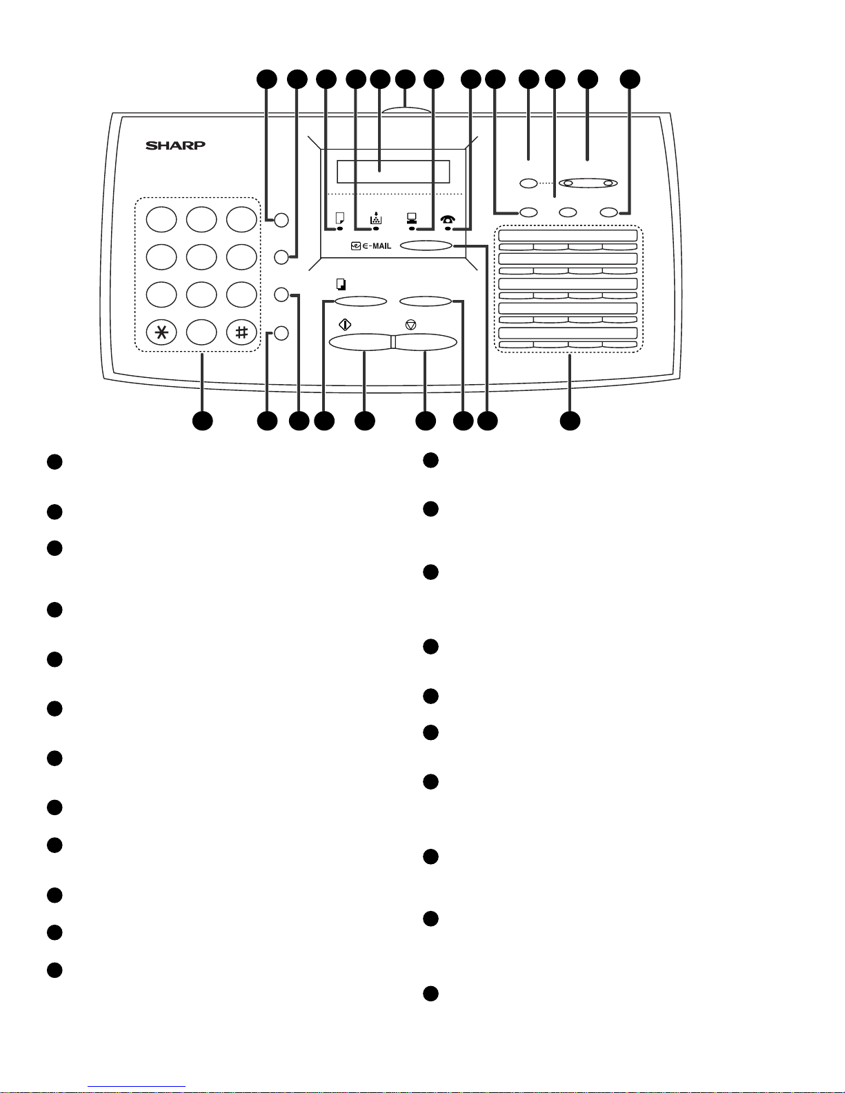
4) Panel key test
This is used to check whether each key is normally operated or not.
According to the key input, LCD is displayed.
1) When the START key is pressed while PANEL KEY TEST is being
displayed, a test will start. Since all of the LEDs will light up in se-
quence until the test is finished, the LED operation can be checked
as well.
2) Press all of the keys one at a time, but do not press the STOP key.
Every time a key is pressed, the name of that key will appear in the
display.
3) Finally, press the STOP key. If there was a key you pressed that was
not detected when the STOP key is pressed, PANEL TEST NG! will
be displayed. When all of the keys have been pressed and detected,
PANEL TEST OK! will be displayed.
Then the display will go blank, which is OK. If there was an NG, any
key which was not pressed or not detected will be printed in the re-
sult table. (For details about the printout format, see the list function
specifications.)
5) Optical adjust mode
In this mode, the optical system is adjusted. Document feeding can be
startedbypressing the STARTkeytwotimes.It can be stopped by press-
ing the STOP key.
6) Check pattern mode
The effective printing area used will be according to the size specified.
A copy of a pattern will be printed, and the printing will be complete.
7) Signal send mode
This mode is used to send various signals to the circuit during FAX com-
munication. Every push of START key sends a signal in the following
sequence.
[ 1] No signals (CML-ON)
[ 2] 14400bps (V. 33)
[ 3] 12000bps (V. 33)
[ 4] 14400bps (V. 17)
[ 5] 12000bps (V. 17)
[ 6] 9600bps (V. 17)
[ 7] 7200bps (V. 17)
[ 8] 9600bps (V. 29)
[ 9] 7200bps (V. 29)
[10] 4800bps (V27ter)
[11] 2400bps (V27ter)
[12] 300bps (FLAG)
[13] 2100Hz (CED)
[14] 1100Hz (CNG)
[15] END
8) Memory clear mode
This mode is used to clear the backup memory and to reset to the fac-
tory default setting.
The content of each setting will be cleared. Then, the initialized list be
output.
Number of buzzer sounds Device checked
1 time <Short sound> MAIN ROM
2 times <Short sounds> S-RAM
3 times <Short sounds> D-RAM
4 times <Short sounds> CPU integrated ROM/RAM