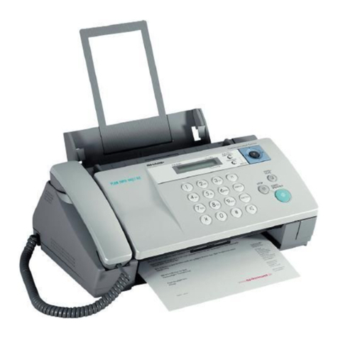
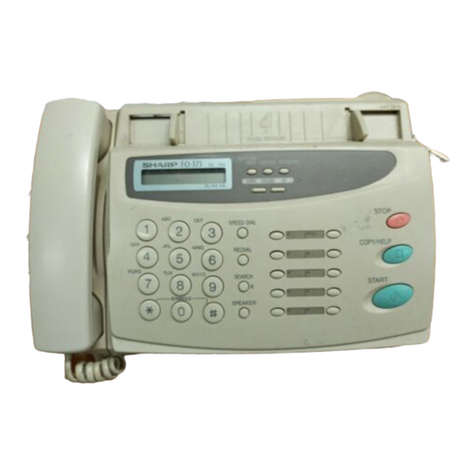
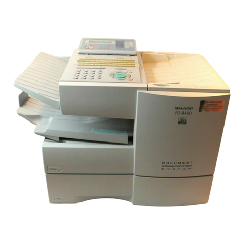
Sharp FO-1450 User manual

—
SHARR
1.INSTALLATION
2.INITIALSETTINGS
3.BASICOPERATIONS
4.ANSWERING MACHINECONNECTION
5.SPECIALFUNCTIONS
6.OPTIONALSE~lNGS
7.PRINTINGOUT REPORTSAND LISTS
8.MAINTENANCE
9.TROUBLESHOOTING
SPECIFICATIONS
QUICK REFERENCEGUIDE
INDEX

WARNING —AUSTEL Regulations state that no unauthorised changes or modifications
to this equipment are permitted.
Note: Complies with AUSTEL and NZ TELECOM standards. Complies with
AS/NZS3548 Emission of Electromagnetic Interference.
These limits are designed to provide reasonable protection against interference in
an installation. This equipment generates, uses and can radiate radio frequency
energy and, if not installed and used in accordance with the instructions, may cause
interference. However, there is no guarantee that interference will not occur in a
particular installation. If this equipment does cause interference to radio or television
reception, which can be determined by turning the equipment off and on, the user
is encouraged to try to correct the interference by one or more of the following
measures:
—Reorient or relocate the receiving antenna.
—Increase the separation between the equipment and the receiver.
—Connect the equipment into an outlet on a circuit different from that to which the
receiver is connected.
—Consult the dealer or an experienced radio/TV technician for help.
FOR YOUR RECORDS
Please record the model number and serial number below, for easy reference, in
case of loss or theft. These numbersare locatedon the rear side of the unit.
Space is also provided for other relevant information.
Model Number
Serial Number
Date of Purchase
Place of Purchase

Welcome to the FO-1450 and thank youfor choosingShatp! In additionto providing
you with the ease and convenienceof plain-paperprinting,the FO-1450 features a
variety of specialfunctions designedto increasethe rangeand power of your
communications.
This manual givesyou easy-to-follow instructionsfor installingand usingthe
FO-1450.The Table of Contents will show you where instructionsfor usingeach
feature are located. Whilst you may not needto readevery sectionin detail at first,
we recommendyou at least reviewthem briefly.
If you haveany questions or problemswhich cannot be solvedby readingthis
manual, pleasecontact your Sharp dealer.
important:
●Thisfacsimile machine is not designed for use on a line whichhas call waiting,
call forwarding, and certain special services offeredby your telephonecompany.
If you attempt to use the fax machine in conjunction withany of theseservices,
you may experience errors during transmissionand receptionof facsimile
messages.
●Thisfax machine is not compatible with digital telephonesystems. No other fax
machines may be connected to the same line.
●Foryour safety, if any of your equipment is not operatingpropedy or should any
physical damage occur to the equipment whereinternalparts may become
exposed, the equipmentshould be immediately disconnectedfrom thephone
line and then thepower line and returned to aSHARPauthorisedService Centre
for inspection, repair, or disposal.
.TheFO-1450is designed to operate in Australia and NewZealand only,
WARNING NOTICE:
NO calls can be made to or from this fax during amainspowerfailure.
INTRODUCTION I

INTRODUCTION
Impofiant safety information
●
●
●
●
●
●
●
●
The socket-outlet must be installed near the equipment and must be easily acces-
sible.
Never install telephonewiring during alightning storm.
Never installtelephonejacks inwet locationsunlessthejack isspecificallydesigned
for wet locations.
Nevertouch uninsulatedtelephonewires or teminals unlessthe telephoneline has
been disconnectedat the network interface.
in Australia,installingor modifyingtelephonelinesshouldonlybedonebyanAustel
licensedserviceman.InNewZealand,installingor modifyingtelephonelinesshould
be done in accordancewith Teiecom wiring practices.
Avoidusingatelephone(otherthanacordlesstype)duringanelectricalstem. There
may be a remote riskof electric shockfrom lightning.
Do not use atelephone in the vicini~ of agas leak.
Do not installor usethe machine nearwater, or when you are wet.Take care notto
spill any liquidson the machine.
●
+Yourfax machineand the telephonesystem
The Australian Austel Registration Number and Ringer EquivalenceNumber(REN)
andthe N.Z.Telecom Registrationand RingerApproximate Loading(RAL)for this
equipmentare shown on the labelson the back of the machine.The telephone
company may requirethese numbers.
Australia: The sum of all Ringer EquivalenceNumberson your telephoneline
should be three or less in order to assure proper setvice from the telephone
company.
New Zealand: The sum of all RingerApproximate Loadingson your telephoneline
should be five or less in order to assure properservice from the telephonecompany.
ii INTRODUCTION

1INSTALLATION
Unpacking Checklist . . . . . . . . . . . . . . . . . . . 1-1
Installing the Imaging Film . . . . . . . . . . . . . . . . 1-2
Attachments and Connections . . . . . . . . . . . . . . . . 1-6
Loading Printing Paper . . . . . . . . . . . . . . . . 1-9
2INITIAL SEITINGS
Setup Guide . . . . . . . . . . . . . . . . . . . . . 2-1
ALook at the Operation Panel . . . . . . . . . . 2-2
Entering Your Name and Fax Number . . . . . . . . 2-4
Entering Letters for Names . . . . . . . . . 2-5
Setting the Date and Time . . . . . . . . 2-7
Selecting the Reception Mode . . . . . . . . . . . . 2-8
Distinctive Ring . . . . . . . . . . . . . . 2-9
Storing Numbers for Automatic Dialling . . . . . . . . 2-10
Volume Adjustment . . . . . . . . 2-14
3BASIC OPERATIONS
Sending Documents . . . . . . . . . . 3-1
Receiving Documents . . . . . . 3-11
Making Copies . . . . . . . . . . . . . 3-15
Making Telephone Calls . . . . 3-18
4ANSWERING MACHINE CONNECTION
Preparations . . . . . . . . 4-1
Using the Connection . . . . . . 4-2
Optional A.M. Connection Settings . . . . 4-5
5SPECIAL FUNCTIONS
Anti Junk Fax . . . . . . . . . 5-1
Memory . . . . . . . . . . . 5-2
Broadcasting . . . . . . . . . 5-4
Polling . . . . . . . . . . . . . . 5-6
Timer Operations . . . . . . . . . . . . . . . . . . 5-9
Entering and Using Programs . . . . . . . . . . . . . 5-11
...
Ill

TABLE OF CONTENTS
6OPTIONAL SEITINGS
7PRINTING OUT REPORTS AND LISTS
8MAINTENANCE
9TROUBLESHOOTING
Problems and Solutions . . . . . . . . . . . 9-1
Messages and Signals . . . . . . . . . . . . . . . . . . . . . 9-4
Clearing Paper Jams . . . . . . . . . . . . . . . . . . . 9-6
SPECIFICATIONS
QUICK REFERENCE GUIDE
INDEX
iv

After unpackingyour fax, makesure you have all the items shown below. If any are
missing, contact your dealer.
Receiveddocument
tray \
n,,
w
Papertray cover -
\
Papertray, Q-’
o~ Rapid key labels
A~Warranty card
3gears and 1flange
\&& ~Adaptor
/% ,:
,,.~(for Australia)
‘, -,,,.
aa ~,,m.. --”<’ —Adaptor
(for New Zealand)
Imagingfilm
Points to keep in mind when setting up
+The fax must be installed on a level surface.
+Keepthe fax away from air conditioners, heaters,direct sunlight, and dust.
4If the fax is moved from acold to awarm place, it is possiblethat condensation
mayform on the reading glass, preventing properscanning of documentsfor
transmission. To removethe condensation,turn on the powerand wait
approximatelytwo hours before usingthe fax.
If your area experiencesahigh incidenceof lightningor power surges, we
recommendthat you install surge protectorsfor the power andtelephone lines.
Surge protectors can be purchasedat most telephonespecialtystores.
—INSTALLATION 1-1

.
The printer unit in your fax creates printedtext and images by applying heat to the
imaging film, which causestoner to betransferredfrom the film to the page. Follow
the steps below to install or replacethe imagingfilm.
1Grasp the finger hold on the right side of
the printing compatiment cover, and pull
up to openthe cover.
2Push backthe green leverson each side
of the printing compartment, and rotate
the printing headframe up and to the
rear,
.Caution! The printing head (the strip
of metal on the undersideof the
frame) applies heat to the printingfilm
It may be hot if adocument hasjust
been printed.
3If you are replacingthe imagingfilm,
take the old film out of the printing com-
partmentand removethe three gears
and the flange from the ends of the
spools.
1-2 INSTALLATION

INSTALLING THE IMAGING FILM
Take the newfilm out of its package,and
insert two of the gears providedwith the
fax into the endsof the spool with film.
Make sure that the two tabs on the gears
fit properly into the slots in the ends of
the spool.
●Do not yet removethe bandwhich
holds the spoolstogether.
5Holdthe empty spool so that the end
.‘.. with only one slot is on the left, and
. . ~lowerthe spools intothe front of the print-
ing compartment.The gears in the ends
of the spool with film should fit into the
slots on each side of the printing com-
partment.
1slot
‘tL/~, 2slots
\2tabs
Cut the bandwhich holdsthe spoolsto-
gether with scissors, and remove it, In-
sert the remaininggear into the right end
of the empty spool andthe flange into
the left end of the emptyspool. Make
sure the tabs on the gear and the flange
fit into the slots in the ends of the spool
(the gear has two tabs andthe flange
has onetab).
INSTALLATION 1-3

INSTALLING THE IMAGING FILM
7Pull the empty spooltoward the backof
the compartment, unwindingthe film as
you pull.
8Insertthe empty spool into the back of
the compartmentso that the gear and
the flange fit into the slots on the sides
of the compartment.
●Makesure that the gear engageswith
the gear below it.
9Wind the film slightly (rotate the gear on
the right side of the empty spool) so that
there is no slack in the film. Makesure
that both edges of the film wind onto the
spool evenly.
1-4 INSTALLATION

INSTALLING THE IMAGING FILM
10 Rotatethe printing headframe back
down, and pressdown on the “PUSH”
mark in the centreof the frame until the
frame clicks into place.Close the printing
compartmentcover.
11 If you replacedthe film, initialise the new
,u~o, ~ ~ film by pressingthe FUNCTION key,
the “6” key, andthe “#” key on the opera-
tion panel. Makesure that “INITIALISE
1FILM” appearsin the display, and then
pressthe START key. (Do not perform
START this step if you installedthe initial sample
m@roll of film.)
●You must initialise FO-16CRfilm to
makeit wind to the starting position for
printing. Ifthis is not done, the first
pagesyou printwill come out blank.
Notethat initialisationwill not be possi-
ble if the papertray is not in the fax.
When to replace the imaging film
The sample roll of imaging film providedwith your fax is capableof printing
approximately 90 pages of A4 size paper. When it is usedup, “FILM END “will
appear in the display. Replace it with the following imagingfilm which is available at
your dealer.
FO-16CR Ifnaging Film
One roll ofFO-16CR imaging film is capableof printingapproximately660 pages of
A4 size paper.
Caution!
The tefi of documents printed with the imaging film is visible on the used film. If
confidential information has been printed, disposeof the film appropriately.
INSTALLATION 1-5

..
. . . ..-’.. .. . “““-”’“AfiACHMENTSANDCONNECTIONS :~~•
.,...,.-—
Connectthe handsetleadto the handset
a q andth~xasshown”
.The ends of the handsetlead are iden-
tical so they will go into either socket.
Placethe handseton the handset rest.
Usethe handsetto makeordinary
phonecalls, or to transmit and
receivedocuments manually.
Installthe fax machinenear an easily ac-
cessible power point 230-240V, 50Hz.
Plugthe power lead into a230-240 V,
50 Hz, grounded(3-prong)AC outlet.
●The fax does not haveapower onloff
switch, so the power is turned on and
off by simply pluggingor unplugging
the power lead.
●Caution: When disconnectingthe fax,
unplugthe telephone line cord before
unpluggingthe power lead.
Attach the receiveddocumenttray by in-
-..<:... ,
.:.. sertingthe tabs into the holes in the rear
\.>., ... -..,
\3
‘<:$\:>*A of the fax.
-::%, ~chy-d+ ,-
\\. \.,,
pi.,.. ../
‘“:->
1-6 INSTALLATION

A~ACHMENTS AND CONNECTIONS
Inseri one end of the telephone line cord
into the adaptor. Insert the other end of
the line cord into the socket on the back
of the fax marked “TEL UNE”. Plugthe
adaptor into the telephone socket on the
wall.
●Be sure to DIUQthe line cord into the
TEL. LINE”so;ket on the fax, Do not
plug it into the TEL. SET socket,
For New Zealand
Moving your faxand reconnecting
Should it be necessa~ to moveyour fax to anew location,first disconnect the
telephone line cord before disconnectingthe power lead. When reconnecting, it is
necessaryto connect the power lead beforeconnectingthe telephone line cord.
INSTALLATION 1-7

A~ACHMENTS AND CONNECTIONS
If desired, you can connect either an answeringmachineor an extension phoneto
your fax.
Connecting an answering machineto the fax as shownbelowwill allow you to
receive both voice and fax messageson the sameline while you are out, For
details on usingthis feature, see Chapter4.
An extension phone connectedto the same line as yourfax can be usedto
make and receive calls. For details on receivingfaxes from anextension phone,
see “Receiving Documents” in Chapter 3.
insert oneend of the answering ma-
chine or extensionphone line either into
the socketon the back side of the adap-
tor (if available), or intothe socket
marked “TEL S~” on the fax (first re-
movethe seal from the socket).
Important: In NewZealand, not all
standardtelephonesand answering
machineswill respondto incoming
ringingwhenconnectedto the extension
socket of the equipment.
Important: When connectingan
answering machine,make surethe line
plug is insertedinto the answerina
machine’stelephone line socket,-notits
telephonesocket.
Note: This type of connection
requiresan FO-80TPadaptor.
This adaptorcan be obtained
throughyour authorised Sharp
1-8 INSTALLATION

. ,.
....... .. LOADING”’PRINTING”PAPER‘-””-‘‘““”-”-““-““”‘“‘““
The papertray holdsthe paperon which receiveddocuments and copies are
printed. Up to 300 sheets of A4 size paperfrom 60 to 90 g/m2can be loaded in the
tray. For the best results,we recommendthat you use Sharp FO-16NC (A4 size)
paper,
‘**-k
Ifthe paper tray is inthe fax machine, re-
movethe cover, Graspthe end of the pa-
per tray, lift it slightly, and pull it out of
the fax machine.
●Important: You must removethe
paper tray from the fax machine to
add paper.
2Pushthe pressureplate down until it
,.. .,, locks into position.
3
‘&
Fanthe papei and then place it in the pa-
per tray, print side up. Makesure the cor-
>, ners of the paper go underthe holders.
..., and then shakethe tray gently to
straighten the paper.
...\: /“’
,,‘
4
e
Insertthe papertray into the fax ma-
.
i~o”<:’ , ,, chine, making sure it clicks into place
*Q% ,,,
/
,(
/>‘*
INSTALLATION 1-9

LOADING PRINTING PAPER
5Replacethe papertray cover.
●The papertray cover also serves as a
tray for original documentswhich
come out of the fax after scanning for
transmissionor copying.You can pull
out the cover as neededto ensure that
it catchesthe documents.
6
STOP
o@
Your fax has been set at the factory to
print on regularpaper. If you have
loadedSharp FO-16NCpaper, you must
changethis setting to “HIGH QUALITY”.
To changethe setting, press the “FUNC-
TION” key,the “6” key,the “*” keytwo
times, andthen press”1” to select regu-
lar, or “2” to select Sharp high quality pa-
per. Whenfinished, pressthe STOP
key. Be sure to changethis setting again
if you changeback to regular paper.
1-10 INSTALLATION

Before you can begin usingyour fax, there are some settingswhich must be made
with the keyson the operation panel, Some of the settings are requiredfor basic
use of your fax, others may or may not be necessarydependingon howyou want to
use the fax. The proceduresfor makingthe settings are describedinthis chapter in
the order shown below, with the exception of answering machineconnection.
Required setiings:
Enteringyour name andfax/telephone number in the fax
Setting the fax to the current date and time
Selectingthe reception mode
Settings which may be necessary:
+Distinctive ring: If you subscribeto adistinctive ring servicefrom your telephone
company (this is aservice which signals voice calls and faxes by different ring
patterns), you will needto set your fax for distinctive ringoperation,See
“Distinctive Ring” in this chapter.
+Answering machineconnection: If you have connectedan answeringmachineto
your fax, you must set Option Setting 10to “YES” as describedin Chapter6,
“Optional Settings”. For more information on preparationsand usingthe
connection,see Chapter4.
Other settings:
+Storing numbersfor automatic dialling: Automatic dialling allows youto dial afull
fax or phone number by simply pressing aRapid Key, or by pressingthe SPEED
DIAL key and entering a2-digit number.To use automaticdialling, you must
store the desired fax and phone numbers in the fax.
+Volume adjustment:Adjustment of the volume of the speakerand ringer.
INITIAL SETTINGS 2-1

Before you makethe settings, take amomentto familiarise yourself with the
operation panel.
Display
This displaysvarious
messagesduring operation
and programming.
\
REDIAL key SPEED DIAL key
Pressthis keyto Pressthis key to
automatically redial dial a2-digit Speed
the last number Dial number.
dialled.
\\\
c
Number keys
Use these keysto dial
numbers,and enter
numbers and letters
during numberlname
storing procedures.
/
HOLD/SEARCH key
Pressthis keyto search
for an automaticdialling
number,or, during aSPEAKER key
phoneconversation,press Pressthis keyto dial a
it to putthe other party on numberwithout picking
hold. upthe handset.
2-2 INITIAL SETTINGS

ALOOK AT THE OPERATION PANEL
FUNCTION key
Pressthis key to RESOLUTION key
~;;~ei~;a~ousspecial ~J~~~t\~~~~~J~tion MEMORYkey
and contrast before Pressthis keyto
RECEPTIONMODE key sendingor copyingascanadocument
Pressthis key to select the document. into memory before
mode of reception.
\ I
1RECEPTION /
MOOE FUNCTIONRESOLUllOhMEMORY
J0000 J
/
/01 1VOLUME
-02 I04 ’05
IDOWN
ma
~06
-
L07 0’ ‘0 c[y~p[w)
1
’11 12 ;13
~START
~161P1 171P2 18/Gl 191G2201POLL
‘u o
I
~\
transmitting it.
VOLUME kevs
Pressthese keysto
/adjust the volume of
the speakerwhen the
SPEAKER key has
been pressed,or the
volumeof the ringer
at all other times.
/STOP key
Pressthis key to stop
operationsbefore
they are completed.
COPY/HELP kev
When adocume’ntis
in the feeder, press
this keyto make a
copy. At any other
time, press this key
to printout the Help
List. aquick
referenceguide to
the operation of your
fax.
Rapid Dial Keys
Pressone of these keysto START key
dial afax or voice number Pressthis key to send
or receiveadocument
automatically, (Notethat you
must attach the Rapid Key
labels.)
INITIAL SETTINGS 2-3

.-... ENTERINGYOURNAMEANDFAXNUMBER . ....
To haveyour name and fax/telephone number (calledthe “Senders name” and
“Sender’s number”) printed at the top of every pageyou transmit. programthem by
pressingthe panel keys as shown below.
+If you enter an incorrect number or letter, press the HOLD/SEARCH key to
movethe cursor back to the mistake,then enter the correct numberor letter. (To
move the cursor forward, pressthe SPEAKER key.)
1‘“~ONaPressthe keysshownat left, “ENTRY
MODE” will appearin the display.
2am Pressthe “#” key2times. “OWN NUM-
BER SET” will appear inthe display.
3START
n
Pressthe START key
@
4Enter your fax number(max. of 20 dig-
its) by pressingthe number keys. (To in-
~@ @ @ @ @ @ sert aspace betweendigits, pressthe
“#” key.To insefl a“+”, pressthe “*”
(Example) key.)
5START
m
Pressthe START key
@
6~~~~ DEnter your name by pressingthe appro-
mam priate number keysas shownon the fol-
a~ lowing page. Presseach key repeatedly
until the desired letter appears in the dis-
aaaa play. (Max. of 24 characters.)
SPEAKER
o
ma
(Example: “SHARP”)
‘m& Pressthe START keyand thenthe
STOP key.
2-4 INITIAL SETTINGS
Table of contents
Other Sharp Fax Machine manuals

Sharp
Sharp FO-P600 User manual

Sharp
Sharp UXB700E User manual

Sharp
Sharp FO-IS115N User manual

Sharp
Sharp UX-177 User manual

Sharp
Sharp FO-90 User manual

Sharp
Sharp UX-465L User manual

Sharp
Sharp F-2700M User manual

Sharp
Sharp FO-155 User manual

Sharp
Sharp UX-2200CM User manual

Sharp
Sharp FO-4700 User manual

Sharp
Sharp FO-5900 User manual

Sharp
Sharp UX-465L User manual

Sharp
Sharp FO-4650 User manual

Sharp
Sharp UX-B30 User manual

Sharp
Sharp FO IS125N - B/W Laser - All-in-One User manual

Sharp
Sharp FO-A660 User manual

Sharp
Sharp FO-2600 User manual

Sharp
Sharp UX-68 User manual

Sharp
Sharp FACSIMILE FO-2950M User manual

Sharp
Sharp FO-1470 User manual