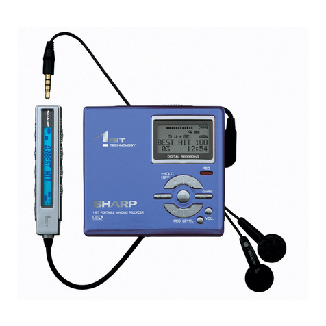
Sharp MD-MT270HS/BK User manual

MD-MT270H
SERVICE MANUAL
SHARP CORPORATION
No. SX299MDMT270H
This document has been published to be used
for after sales service only.
The contents are subject to change without notice.
PORTABLE MINIDISC RECORDER
Page
SAFETY PRECAUTION FOR SERVICE MANUAL ............................................................................................................... 2
SPECIFICATIONS ................................................................................................................................................................. 3
NAMES OF PARTS ............................................................................................................................................................... 4
DISASSEMBLY...................................................................................................................................................................... 5
REMOVING AND REINSTALLING THE MAIN PARTS......................................................................................................... 6
ADJUSTMENT ........................................................................................................................................................................ 7
MD ERROR MESSAGE DISPLAY CONTENT LIST ........................................................................................................... 21
NOTES ON SCHEMATIC DIAGRAM .................................................................................................................................. 22
TYPES OF TRANSISTOR AND DIODE .............................................................................................................................. 22
BLOCK DIAGRAM ............................................................................................................................................................... 23
SCHEMATIC DIAGRAM ...................................................................................................................................................... 24
WIRING SIDE OF P.W.BOARD........................................................................................................................................... 32
VOLTAGE ............................................................................................................................................................................ 36
WAVEFORMS OF MD CIRCUIT ......................................................................................................................................... 37
TROUBLESHOOTING ......................................................................................................................................................... 38
FUNCTION TABLE OF IC.................................................................................................................................................... 41
PARTS GUIDE/EXPLODED VIEW
PACKING OF METHOD (FOR U.K. ONLY)
CONTENTS
• In the interests of user-safety the set should be restored to its
original condition and only parts identical to those specified be
used.
MODEL
MD-MT270H(S)/(BK)

– 2 –
MD-MT270H
Precaution to be taken when replacing and servicing the laser pickup.
The following precautions must be observed during servicing to protect your eyes against exposure to the laser.
Warning of possible eye damage when repairing:
If the AC adaptor or batteries are connected when the top housing (disc cover) of the unit is removed, and the PLAY key is
pressed, the laser will light up during focus access (2-3 seconds). (Fig. 2-1) During the operation, the laser will leak from the
opening between the magnetic head and the mechanical chassis (Fig. 2-2). In order to protect your eyes, you must not look
at the laser during repair. Before repairing be sure to disconnect the AC adaptor and remove the batteries.
Precaution to be taken when replacing and servicing the
Laser Pickup.
THEAEL(ACCESSIBLEEMISSIONLEVEL)OFTHELASER
POWEROUTPUTISLESSTHANCLASS1BUTTHELASER
COMPONENT IS CAPABLE OF EMITTING RADIATION
EXCEEDING THE LIMIT FOR CLASS 1. THEREFORE IT IS
IMPORTANTTHATTHEFOLLOWINGPRECAUTIONSARE
OBSERVED DURING SERVICING TO PROTECT YOUR
EYES AGAINST EXPOSURE TO THE LASER BEAM.
(1) When the cabinet has been removed, the power is
turnedonwithouta compact disc, and the Pickup is on
aposition outerthanthelead-in position, theLaserwill
light for several seconds to detect a disc. Do not look
into the Pickup Lens.
(2) The Laser Power Output of the Pickup inside the unit
and replacement service parts have already been
adjusted prior to shipping.
(3) NoadjustmenttotheLaserPowershouldbeattempted
when replacing or servicing the Pickup.
(4) Under no circumstances look directly into the Pickup
Lens at any time.
(5) CAUTION - Use of controls or adjustments, or
performance ofprocedures other than thosespecified
herein may result in hazardous radiation exposure.
SAFETY PRECAUTION FOR SERVICE MANUAL
Laser Diode Properties
Material: GaAlAs
Wavelength: 785 nm
Pulse time:
Read mode: 0.8 mW Continuous
Write mode: max 10 mW 0.5S
min cycle 1.5S
Repetition
Bottom Cabinet
Magnet head
Optical pickup
,,
,
,,,
Laser Beam
Optical Pick-Up
Main PWB
Spindle motor
Mechanism
Chassis Magnet Head
Figure 2-1 Figure 2-2
English:
This product is classified as a CLASS 1 LASER PRODUCT.
German:
Dieses Produkt ist ein Laserprodukt der Klasse 1.
French:
Ce Produit est Classifié comme étant un PRODUCTO
LASER DE CLASSE 1.
VARO ! Avattaessa ja suojalukitus ohitettaessa olet alttiina näkymättömälle lasersäteilylle. Älä katso säteeseen.
VARNING! Osynlig laserstralning när denna del är öppnad och spärren är urkopplad. Betrakta ej strälen.

– 3 –
MD-MT270H
FORACOMPLETEDESCRIPTIONOFTHEOPERATIONOFTHISUNIT,PLEASEREFERTO
THE OPERATION MANUAL.
SPECIFICATIONS
Power source: DC 5 V: AC adaptor (AC 230
V, 50/60 Hz)
DC 1.5 V: Commercially avail-
able, "AA" size
(LR6), alkaline bat-
tery x 1
DC 4.5 V: Optionalcaradaptor,
AD-CA20X (for cars
with a 12-24 V DC
negative earth elec-
trical system)
Power consumption: 7 W (AC adaptor)
Output power: RMS: 20 mW (10 mW + 10 mW)
(0.2 % T.H.D.)
Dimensions: Width: 83 mm (3-9/32")
Height: 28 mm (1-1/8")
Depth: 77 mm (3-1/32")
Weight: 107 g (0.24 lbs.) without battery
Input socket: Line/optical digital
Output socket: Earphones (impedance: 32
ohms)
Input sensitivity:
Output level:
Battery life:
When using a commercially available, high capacity, "AA"
size (LR6), alkaline battery
●The continuous recording time is for analogue inputs
when the volume level is set to "VOL 0".
●The continuous play time shows the value when the vol-
ume level is set to "VOL 15".
●The above values are the standard values when the unit is
used at an ambient temperature of 25°C (77°F).
●The operating time when using an alkaline battery may be
different, depending on the type and manufacturer of the
battery, and on the operating temperature.
Type: Portable MiniDisc recorder
Signal readout: Non-contact, 3-beam semicon-
ductor laser pickup
Audio channels: Stereo 2 channels/monaural 1
channel
Frequency response: 20 - 20,000 Hz ( 3 dB)
Rotation speed: Approx. 400 - 1,800 rpm CLV
Error correction: ACIRC (Advanced Cross Inter-
leave Reed-Solomon Code)
Coding: ATRAC/ATRAC3 (Adaptive
TRansform Acoustic Coding),
24-bit computed type
Recording method: Magnetic modulation overwrite
method
Sampling frequency: 44.1 kHz (32 kHz and 48 kHz sig-
nals are converted to 44.1 kHz,
and then recorded.)
Wow and flutter: Unmeasurable (less than 0.001
% W. peak)
Reference input
level Input impedance
LINE
100 mV 20 k ohms
Specified out-
put Maximum out-
put level Load imped-
ance
Ear-
phones - 10 mW + 10
mW 32 ohms
LINE 250 mV (-12
dB) - 10 k ohms
Stereo Continuous recording: Approx. 8.5 hours
Continuous play: Approx. 33 hours
2 times
long Continuous recording: Approx. 12 hours
Continuous play: Approx. 44 hours
4 times
long Continuous recording: Approx. 18 hours
Continuous play: Approx. 52 hours
Specifications for this model are subject to change without prior
notice

– 4 –
MD-MT270H
NAMES OF PARTS
■
Main unit
1.Open Lever
2.Battery Cover
3. Menu/Enter Button
4.Stop/Power Off/Hold Button
5.Play/Pause Button
6.Bass/Delete/Synchro Button
7.Earphones/Line Output Socket
8.Volume/Cursor Buttons
9.Optical/Line Input Socket
10.Record/Track Mark Button
11.5 V DC Input Socket
12.Fast Forward/Fast Reverse/
Recording Level/Menu Select/
Name Select Buttons
■
Display panel
1.Level Meter
2.Random Indicator
3.Repeat Indicator
4.Long-play/Recording Mode Indicator
5.Monaural Mode Indicator
6.Battery Indicator
7.Play Indicator
8.Pause Indicator
9.Disc Name Indicator
10.Record Indicator
11.Synchro Recording Indicator
12.Character/Time Information Indicator
13.TOC Indicator
14.Track Number Indicator
13
6
78910 11
12
123 45
6
7
891011 13
14
45
2
12

– 5 –
MD-MT270H
DISASSEMBLY
Cares before disassembling
When assembling the machine after disassembling or
repair, observe the following requirements so as to ensure
safety and performance.
1.Removethebatteriesfromthemachine,andtakeoutthe
mini-disc.
2. When assembling after repair, be sure to position the
wires in the same location.
Use the specified screws to fix the cabinet and the
mechanismunit.Theuseof the screwswithlengthother
than specified may cause contact with the mechanism
unit resulting in malfunction.
3.Whenrepairing,paycloseattentionsonottodamagethe
IC from static electricity.
Caution:
Carefullyhandle the mainPWB and flexible PWB.After removing the
flexible PWB (1*) for the optical pickup from the connector, do not
touch directly the front end of flexible PWB with your hand so as to
prevent damage of optical pickup by static electricity.
(B1) x2
ø1.4x2.5mm
(C1) x2
ø1.4x2.5mm
(C1) x1
ø1.4x2.5mm
(C1) x1
ø1.4x2.5mm
(A3) x1 (C2) x1
Bottom Cabinet
Main PWB
(C2) x1*
Pull
Pull Pull
(D2) x1
ø1.4x1.5mm
Bracket
Bracket
Mechanism Unit
(D1) x2
ø1.4x2.5mm
Battery Box
1 Top Cabinet 1. Open the Bottom cabinet. 5-1
2. Open the Battery Door.
3. Screw .....................(A1) x4
4. Screw .....................(A2) x1
5. Flexible PWB..........(A3) x1 5-2
2 Bottom Cabinet 1. Screw .....................(B1) x2 5-2
3 Main PWB 1. Screw (C1) x4 5-2
2. Flexible PWB (C2) x2
4 Mechanism Unit 1. Screw (D1) x2 5-3
2. Screw (D2) x1
REMOVAL PROCEDURE
STEP FIGURE
Figure 5-1
Figure 5-2
Figure 5-3
(A1) x2
ø1.4x2.5mm
(A1) x1
ø1.4x2.5mm
(A1) x1
ø1.4x2.5mm
(A2) x1
ø1.4x4mm
Battery Door
Bottom Cabinet
Top Cabinet
Open Lever

– 6 –
MD-MT270H
REMOVING AND REINSTALLING THE MAIN PARTS
Removethemechanismaccordingtothedisassemblingmeth-
ods 1 to 4. (See Page 5.)
How to reinstall the optical pickup
(See Fig. 6-4.)
1. Remove the screw (E1) x 1 pc., and remove the spring.
2.Removethescrew(E2)x1pc.,andremovetheshaftguide.
3. Slowly raise the optical pickup.
How to remove the magnetic head (See Fig. 6-1.)
1. Remove the solder joints (A1) x 2 of the head flexible plate.
2. Remove the screws (A2) x 2 pcs. of the magnetic head.
Note:
Mount carefully so as not to damage the magnetic head.
How to remove the Lift motor (See Fig. 6-4.)
1.Remove the solder joints(D1) x 2 of the lift motor lead wire.
2. Remove the screw (D2) x 1 pc., and remove the lift motor.
Note:
Take care so that the motor gear is not damaged.
(If the gear is damaged, noise is caused.)
How to remove the sled motor (See Fig. 6-3.)
1.Removethestopwasher (C1) x1pc.,andremove the drive
gear (C2) x 1 pc.
2. Remove the solder joints (C3) x 3 of flexible PWB.
3. Remove the screws (C4) x 2 pcs., and remove the sled
motor.
Note:
Take care so that the motor gear is not damaged.
(If the gear is damaged, noise is caused.)
How to remove the spindle motor (See Fig. 6-2.)
1. Remove the solder joints (B1) x 4 of flexible PWB.
2. Remove the screws (B2) x 3 pcs., and remove the spindle
motor.
MD Mechanism
Spindle
Motor
Mechanism Flexible
PWB Solder joints
(B1)x4
(B2) x3
ø1.4 x1.8mm
MD Mechanism
Mechanism Flexible
PWB Solder joints
(C3)x3 (C4) x2
ø1.4 x1.2mm
Stop Washer
(C1)x1
Drive Gear
(C2)x1
Sled Motor
Mechanism Flexible
PWB Solder joints
(D1)x2
(D2) x1
ø1.4 x3.3mm
Lift Motor
Spring
Optical Pickup Unit
(E1) x1
ø1.4 x1.2mm
(E2) x1
ø1.4 x2.5mm
Shaft Guide
(A2) x2
ø1.4 x1.8mm
MD Mechanism
Magnetic head Mechanism Flexible
PWB Solder joints
(A1)x2
Figure 6-1
Figure 6-2
Figure 6-3
Figure 6-4

MD-MT270H
– 7 –
Entering the TEST mode
1. Setting at port (power nonconnected state)
(1) Set the port as follows.
TEST1 : "Low" (TP416)
TEST0 : "High"
(2) Turn the Power ON.
(3) Test Mode START [ T E S T _ ]
2. Setting by special button operation (in standby state)
(1) Press the VOL.+button and PLAY button. Continue to hold down the PLAY button to release the VOL.+button and press the VOL.–
button.
(2) Normal mode setting initialization (BASS setting, VOL setting, etc.)
*Since the unit is changed to the setting for production line inspection , be sure to set it to the default setting state in the following default
setting procedure before returning it to the user.
(3) Test Mode START [ T E S T _ ]
(4) When the VOL.+button is pressed, indication of microcomputer version for one second [ X 2 8 A d X ]
(5) When the VOL.–button is pressed, whole LCD lighting for 2 seconds
1 High reflection disc MMD-110 (TEAC Test MD) 88GMMD-110
2 Low reflection disc MMD-212 (TEAC Test MD) 74-minute disc 88GMMD-212
3 Low reflection disc MMD-213A (TEAC Test MD) 80-minute disc 88GMMD-213A
4 Low reflection disc Recording minidisc UDSKM0001AFZZ
ADJUSTMENT
Test disc
MD adjustment needs two types of disc, namely recording disc (low reflection disc) and playback-only disc (high
reflection disc).
Type Test disc Parts No.
Note: Use the low reflection disc on which music has been recorded.
Test Mode
1. AUTO 1 Mode • Perform preliminary automatic adjustment.
• If the combination of mechanism and pickup
PWB has been changed, be sure to start from
AUTO1.
2. AUTO 2 Mode
• Perform ATT (attenuator) automatic adjustment.
• Perform continuous playback (error rate display,
jump test)
3. TEST-PLAY Mode
• Continuous playback from the specified address
is performed.
• 1 line, 10 lines or 100 steps manual jump is
performed.
• C1 error rate display (pit section), ADIP error
rate display (groove section)
• The temperature correction is performed only when
servo start is performed, but the posture correction
is not performed during continuous playback.
4. TEST-REC Mode
• Continuous record from the specified address
is performed.
• Change of record laser output(servo gain is also
changed according to laser output).
• The temperature correction is performed only
when servo start is performed, but the posture
correction is not performed during continuous
recording.
5. MANUAL 1 Mode
• Temperature is displayed. (Updating in real time)
• Seeing the displayed adjustment value, perform
preliminary manual adjustment.
(Error rate indication, jump test)
6. MANUAL 2 Mode
• Temperature is displayed. (Updating in real time)
• Seeing the displayed adjustment value perform
manfully the preliminary adjustment.
(Error rate indication, jump test)
• Continuous playback is performed
(Error rate display, jump test).
7. RESULT 1 Mode
• The value adjusted in AUTO1 or MANUAL1 is
indicated.
• (Execution in servo "OFF" state").
8. RESULT 2 Mode
• The value adjusted in AUTO 2 or MANUAL 2 is
indicated.
• Adjustment value is changed manually.
(Error rate display, jump test).
9. DIGITAL INPUT Mode
• Digital input information is displayed.
10. ERROR INFORMATION
• Error information is displayed.
Mode • Error information is initialized
11. NORMAL Mode
• The mode is changed from the TEST mode to
the normal mode without adjustment.
• In the normal mode the internal operation mode,
memory capacity, etc. areindicated.
• In the normal mode both temperature correction
and posture correction are perfomed.
12. EEPROM Mode
• Factors of digital servo are changed manually.
(Each servo is turned on individually.)
• Cut-off frequency of BASS1, BASS2 and BASS3
is selected manually.
• Temperature detection terminal voltage is
measured, and the reference value is set.
• Defaults are selected and set.
• Setting of EEPROM protect area is updated.
(In case of protect releasing)
13.AUTO J Mode
•
AUTO 1/2, focus balance adjustment, TEST-
PLAY (ADIP/C1 error check), EEPROM are
updated sequentially.
EEPROM version
Destination
Microcomputer version
Leaving the TEST mode
(1) Press the STOP button in the TEST mode stop state.
Shipping setting method
Holding down simultaneously the VOLUME –Button and PLAY Button of the set unit without disc, supply the power from the DC IN plug.
After the indication "INIT" -> "BYE OK" disappears, release the power supply of DC IN.

MD-MT270H
– 8 –
• Whenever the MENU button is pressed in the continuous
playback mode, the indication changes as follows.
* Pre-mastered disc
Continuous playback (SUBQ address indication)
[ S Q ]
Continuous playback (C1 error indication)
[ C E ]
Continuous playback (SUBQ address indication)
[ S Q ]
* Recordabl disc
Continuous playback (ADIP address indication)
[ A P ]
Continuous playback (C1 error indication)
[ C E ]
Continuous playback (ADIP error indication)
[ A E ]
Continuous playback (ADIP address indication)
[ A P ]
4. TEST-REC Mode
• When the STOP button is pressed while the TEST-REC
menu appears, or in the TEST-REC mode or continuous
record mode, the mode changes to the TEST mode stop
state.
•
When the PLAY button is pressed while the TEST-REC
menu appears, the continuous record is initiated from the
current pickup position.
• Whenever the MENU button is pressed in the TEST-REC
menu, the target address changes as follows.
0032 →03C0 →0700 →08A0 →0950 →0032 →........
When the PLAY
button is pressed while a target
address is displayed, continuous playback is performed
after searching that address.
• Whenever the REC button is pressed in the TEST-REC
mode target address is displayed, the digit which is
changed by the FAST FORWARD/FAST REVERSE /
button changes as follows.
0032 →0032 →0032 →0320 →........
• When the FAST FORWARD button Is pressed in the
TEST-REC mode target address is displayed, the digit of
address specified by the BASS button is set to +1h.
(0 to F)
• When the FAST REVERSE button is pressed in the
TEST-REC mode target address is displayed, the digit of
address specified by the BASS button is set to -1h.(0 to F)
*
When the FAST FORWARD/FAST REVERSE /
button is held down, the setting changes continuously,
one cycle being 100 ms.
Operation in each TEST mode
1. AUTO1 Mode
•When the STOP button is pressedwhile the AUTO1 menu
appearsor during automaticadjustment, the modechanges
to the TEST mode stop state. At this time the adjustment
value is not output.
• Be sure to adjust, using the specified disc MMD-213A or
MMD-212.
Atthistimereleasethe EEPROM (IC402)protection. (Refer
to EEPROM write procedure.)
• Adjustment NG; Adjustment item out of range, focus ON
failure, and adjustment error
• When the PLAY button is pressed while ADJ. OK is
displayed, AUTO2 is executed.
2. AUTO2 Mode
•When the STOP button is pressedwhile the AUTO2 menu
appearsor during automaticadjustment, the modechanges
to the TEST mode stop state. At this time the adjustment
value is not output.
• Adjustment NG; Adjustment item out of range, and adjust-
ment error.
• When the PLAY button is pressed while ADJ. OK is
displayed, TEST_PLAY is executed.
3. TEST-PLAY Mode
• When the STOP button is pressed while the TEST-PLAY
menu appears, or in TEST-PLAY or continuous playback
mode, the mode changes to the TEST mode stop state.
• When the PLAY button is pressed while the TEST-PLAY
menu appears, continuous playback is initiated from the
current pickup position.
• Whenever the MENU button is pressed in the TEST-PLAY
menu, the target address changes as follows.
0032 →03C0 →0700 →08A0 →0950 →0032 →........
When the PLAY button is pressed while a target address
isdisplayed,continuousplaybackisperformedaftersearch-
ing that address.
• Each time the REC button is pressed while the TEST-PLAY
modetargetaddressisdisplayed,thedigitwhich is changed
by pressing the FAST FORWARD/FAST REVERSE /
button is changed as follows.
0032 →0032 →0032 →0032 →........
• When the FAST FORWARD button is pressed in the
TEST-PLAY mode target address is displayed, the digit of
addressspecifiedbytheENTERbuttonissetto+1h.(0toF)
• When the FAST REVERSE button is pressed in the
TEST-PLAY mode target address is displayed, the digit of
addressspecified by the ENTERbutton is set to -1h. (0 to F)
*
When the FAST FORWARD/FAST REVERSE /
button is held down, the setting changes continuously, one
cycle being 100 ms.
• When the BASS button is pressed in the continuous play-
back mode, the number of jump lines changes as follows.
1TR →10TR →100STP →1TR →........
* Afterthenumber of jumplinesis indicated foronesecond,
the address indication is restored [ T R _ ]
• When the FAST FORWARD button is pressed in the
continuous playback mode, the specified number of lines
is jumped in the FWD direction.
• When the FAST REVERSE button is pressed in the
continuous playback mode, the specified number of lines
is jumped in the REV direction.
* When the FAST FORWARD/FAST REVERSE
/
button is held down, jump is repeated every
approx. 100 ms.

MD-MT270H
– 9 –
5. NORMAL Mode
• When the STOP button is pressed while the NORMAL
menu appears, the mode changes to the TEST mode stop
state.
• Indication during operation
Indication of memory capacity on main unit LCD
[ ] + Level meter
: Internal mode
: Address (Cluster section)
: Address (Sector section)
• Selection of sound volume, BASS, etc. is possible (without
indication)
• Recording is also possible.
• If the STOP button is pressed during operation in the
NORMAL mode, the NORMAL mode is canceled, and the
power is turned off.
6. Error data display Mode
• Reversing when FAST REVERSE button is pressed
• When the STOP button is pressed while the error data
indication menu appears or during error data indication, the
mode changes to the TEST mode stop state.
• Error data 0 is the latest error.
• Error which occurred in the TEST mode is also stored in the
memory.
• When the MENU button is pressed while the error data
indication menu appears, the error data is initialized.
[ C L E A R _ ]
• : Error Code
Explanation of error history code
13h :
Excessive number of retry to draw servo during its
adjustment.
16h : COUT detection time over during servo adjustment.
17h : The level of input signal from the RF amplifier is out of
the allowable range.
1Fh :Cannot clear the factor of ENDEC DINT.
21h : Cannot focus on the disc.
22h : Cannot start up the spindle.
23h : Track search time over.
32h : Cannot read P-TOC.
42h : Cannot read U-TOC.
44h : Cannot write U-TOC.
45h : Cannot perform write test of U-TOC.
52h : Cannot write SD. (Sound Data)
72h : Check sum error occurred when reading EEPROM.
73h :
Cannot operate the recording head (by using the EJECT
lever).
82h : DC-IN power voltage error.
83h :
Temperature
sensor input voltage error.
91h :
The ambient temperature is out of the allowable range.
7. Auto J Mode
•AUTO1/2,focusbalanceadjustment,TEST-PLAY(ADIP/C1
error check), EEPROM are updated sequentially.
• If the STOP button is pressed while processed, the same
operation as the normal STOP button operation will be
performed.

MD-MT270H
– 10 –
EEPROM (IC402) writing procedure
1. Procedure to replace EEPROM and write initial
value of microcomputer in EEPROM
(1) Replace EEPROM.
(2) Refer to the latest EEPROM data list.
(3) PresstheVOL.+buttonandPLAYbutton.Continueto
hold down the PLAY button to release the VOL.+
button and press the VOL.–button.
(4) Press the VOL.+button, version display.
[ V e r . ]
EEPROM version
MicrocomputerROMversion
(5) Press the VOL.–button, the whole LCD lights.
(6) Test mode stop state.
[ T E S T ]
(7) Pressthe"BASS"button,andpress3timesthe"FAST
REVERSE " button.
[ E E P R O M ]
(8) Performtheoperationtodisplay"EEPROMSETTING
ENTER CHART", compare the EEPROM DATA LIST
with the display, and set according to the EEPROM
DATA LIST with the VOL.+or VOL.–button.
(9) Set the temperature reference. (Refer to the Tem-
perature Reference Setting Method.)
(10)
Set according to the EEPROM DATA LIST.
(11)
Press the Stop button.
[ T E S T ]
(12)
Press the Stop button.
(13)
After data is written in EEPROM, turn off power .
(14)
Restore protection of EEPROM.
2. Temperature reference setting method
[1] Measurement, calculation and setting procedure
(1) Set the TEST mode.
• Set TEST 1, 0 = '01', and turn on power
(or set PLAY ON in standby state).
(2) PresstheVOL.+buttonandPLAYbutton.Continueto
hold down the PLAY button to release the VOL.+
button and press the VOL.–button.
(3) Start the EEPROM mode 'Temp' menu.
• ButtonoperationinorderofMENU,FASTREVERSE
x 3 times, PLAY , PLAY in the test mode
STOP state.
• 'TM§§ ' is displayed. (§§= Temperature code,
= Temperature reference)
(4) Once press FAST FORWARD , and determine
the displayed microcomputer TEMP input AD value.
• 'TPin##' is displayed. (## = TEMP input AD value)
(5) At the ambient temperature, determine the tempera-
ture corrected value from the temperature measure-
ment value correction table.
(6) Determine the temperature reference, using the fol-
lowing formula.
• Temperature reference = Microcomputer TEMP
input AD value + Temperature corrected value
(7) Set the temperature reference value by button opera-
tion, and check whether the temperature code indica-
tion corresponds to "Temperature Code Identification
Table".
[2] Temperature measurement value correction table
[3] Temperature code identification
X
Ambient
temperature Temperature
correction Center
temperature
– 8oC ~ +10oC 08h + 0.5oC
+ 3oC ~ +21oC 07h + 12.0oC
+14oC ~ +33oC 06h + 23.6oC
+26oC ~ +43oC 05h + 35.0oC
Ambient
temperature Temperature
correction
+ 8oC ~ +10oC - 05h + 9.2oC
+11oC ~ +13oC - 04h + 12.1oC
+14oC ~ +16oC - 03h + 14.9oC
+17oC ~ +19oC - 02h + 17.8oC
+20oC ~ +22oC - 01h + 20.7oC
+23oC ~ +25oC±00h + 23.6oC
+26oC ~ +27oC + 01h + 26.5oC
+28oC ~ +30oC + 02h + 29.4oC
+31oC ~ +33oC + 03h + 32.3oC
Center
temperature

MD-MT270H
– 11 –
EEPROM DATA LIST (EEPROM version d)
Focus setting
F G 1 _ 4 0 H
F G 2 _ 9 0 H
F F 0 _ 1 0 H
F F 1 _ 7 0 H
F F 2 _ E 5 H
F f 0 _ 1 0 H
F f 1 _ 4 8 H
F f 2 _ E A H
F Z H _ E D H
F L n _ 0 9 H
F L p _ 0 6 H
D J G _ 0 E H
F S S _ 2 8 H
F T S _ 1 8 H
F S B _ 4 0 H
F T B _ 2 8 H
F G M _ 6 6 H
T V G _ 8 4 H
T O 1 _ 5 0 H
T O 5 _ 5 8 H
T O R _ 5 8 H
P L E _ 8 B H
R F T _ 0 0 H
Item display Set values Spindle setting
S P G _ 3 0 H
S P i _ 9 A H
S P m _ 6 2 H
S P o _ 4 F H
P G M _ E 0 H
S P 1 _ 1 0 H
S P 2 _ 6 0 H
S P 3 _ F 2 H
S P 4 _ F 2 H
S P 5 _ 1 0 H
S p 2 _ 6 0 H
S p 5 _ 1 0 H
S D 1 _ 7 F H
S D 2 _ 7 F H
S P K _ E B H
M P G _ 2 8 H
S P L _ 6 0 H
S P W _ 0 F H
S P B _ 6 6 H
S R i _ C 0 H
S R m _ 9 A H
S R o _ 7 B H
S B R _ 6 0 H
O S L _ 1 4 H
P J G _ 4 6 H
Item display Set values
Tracking setting
Item display Set values
T G 1 _ 1 7 H
T G 2 _ 4 0 H
T F 0 _ 1 0 H
T F 1 _ 7 0 H
T F 2 _ E 0 H
T f 0 _ 1 0 H
T f 1 _ 4 0 H
T f 2 _ E 4 H
T F S _ 0 0 H
T B o _ 2 0 H
T B t _ 3 4 H
T K o _ 2 0 H
T K t _ 3 2 H
T K T _ 1 6 H
T D o _ 6 7 H
T D t _ 0 E H
T D T _ 1 6 H
S C o _ 0 0 H
S C t _ 3 A H
S C m _ 4 8 H
C L p _ 2 4 H
C L r _ 3 0 H
J P I _ 0 E H
T H P _ 0 2 H
T H G _ 0 2 H
T 0 P _ F 0 H
T 0 G _ E F H
T 1 P _ 1 8 H
T K n _ 1 1 H
T K N _ 2 6 H
T K L _ 4 0 H
Sled setting
S K S _ 7 F H
S K L _ 7 F H
S L C _ 2 2 H
S T L _ 0 8 H
S T M _ 4 2 H
S T E _ A 6 H
S D V _ 6 0 H
S J P _ 0 3 H
W T m _ 1 8 H
S R V _ 5 4 H
S L T _ 5 8 H
M V S _ 0 A H
S L S _ 2 8 H
S K E _ 2 5 H
S D E _ 1 C H
B P E _ 0 2 H
B P W _ 4 A H
B P 1 _ 8 7 H
B R E _ 9 3 H
B R W _ 2 3 H
S R S _ 0 0 H
Item display Set values

MD-MT270H
– 12 –
C T 0 _ 0 3 H
C T 1 _ 0 1 H
C T 2 _ B B H
C T 3 _ 5 0 H
U S A _ 1 8 H
R C E _ 9 4 H
X 2 T _ F F H
S D F _ 1 F H
F B 0 _ F C H
B H S _ 0 0 H
F B L _ 1 6 H
M C 2 _ 0 0 H
M C 4 _ 0 0 H
L 2 H _ 8 1 H
L 4 H _ 8 0 H
B S 0 _ 3 A H
B S 1 _ 9 8 H
B U 0 _ 0 1 H
B D 0 _ 0 5 H
B D 1 _ D C H
B M K _ 1 E H
C S T _ 6 9 H
I J U _ 4 1 H
I J D _ 5 5 H
M C T _ C 1 H
E R C _ 5 A H
C V 0 _ 0 0 H
C V 1 _ 1 5 H
S S K _ 0 0 H
A C T _ 6 8 H
C 1 E _ 5 2 H
A D E _ C 0 H
L C V _ 1 2 H
R C 0 _ D 7 H
R C 1 _ D 6 H
R 2 0 _ 8 0 H
R 2 1 _ 2 0 H
R 4 0 _ B F H
R 4 1 _ 0 2 H
M F P _ 4 B H
S P M _ 0 0 H
M S L _ 0 0 H
U S 0 _ 0 0 H
U S 1 _ 0 0 H
U S 2 _ 0 0 H
w E 0 p _ 5 4 H
w E 2 _ 4 6 H
w E 3 p _ 0 5 H
w E 3 g _ 0 0 H
w E A _ 1 6 H
w E F _ 0 0 H
K 1 0 _ 0 F H
K 1 1 _ 8 E H
ADJ. SET setting
Item display Set values
C O K _ 2 8 H
F A T _ C 0 H
T A T _ 3 E H
C A T _ 4 0 H
F A B _ 6 4 H
Bass setting Item display Set values
B S 0 _ 0 2 H
B S 1 _ 0 1 H
B S 2 _ 1 2 H
B S 3 _ 4 0 H
B S 4 _ 2 2 H
B S 5 _ 2 2 H
B S 6 _ 0 3 H
B S 7 _ 2 2 H
B S 8 _ 0 0 H
Control setting
Item display Set values
DEQ. SET setting
Item display Set values
H Q 1 _ 9 0 H
H Q 2 _ 9 0 H
H S G _ 1 1 H
H S O _ F F H
L Q 1 _ 9 0 H
L Q 2 _ 9 0 H
L S G _ 1 2 H
L S O _ 0 0 H
G Q 1 _ 9 8 H
G Q 2 _ 8 4 H
G S G _ 1 2 H
A L S _ 3 F H
R C N _ 0 0 H
E Q R _ 0 0 H

MD-MT270H
– 13 –
: Test Mode STOP
: Auto 1 & 2, Focus balance adjustment menu
: Pre-auto adjustment menu
: ATT auto adjustment menu
: Continuous record menu
: EEPROM setting menu
BASS
T E S T
Slide external
periphery move Slide internal
periphery move
Test Mode Menu
Test Mode Change Chart
A U T O J
A U T O 1
FAST FORWARD FAST REVERSE
FAST REVERSE
FAST FORWARD FAST REVERSE
T R E C
FAST FORWARD FAST REVERSE
: Continuous playback menu
T P L A Y
FAST FORWARD FAST REVERSE
: Digital input signal monitor menu
D i n M o n
FAST FORWARD FAST REVERSE
FAST FORWARD
FAST FORWARD
FAST REVERSE
FAST REVERSE
FAST FORWARD
* When the [STOP ] button is pressed in specific menu, the "TEST MODE STOP" state is set.
* When the [PLAY ] button operation is performed in the specific menu, the operation of this
menu is executed.
: Pre-adjustment value check menu
R S L T 1
: ATT adjustment value check menu
R S L T 2
: Pre-manual adjustment menu
M A N U 1
: ATT manual adjustment menu
M A N U 2
: Error history display menu
E D A T A
: Test mode normal playback menu
N O R M A L
E E P R O M
A U T O 2
: Preautomatic Adjustment menu
: Preadjustment error (adjustment value output)
: During preadjustment adjustment
Adjustment error
Normal end
: Preadjustment normal end (adjustment value output)
: During ATT automatic adjustment
PLAY
PLAY
A U T O 1
Preautomatic Adjustment
A D J . O K
A D J . N G
A T 2
A T 1
* When the [STOP ] button is pressed in specific menu, the "TEST MODE STOP" state is set.
* " " represent the adjustment number as follows.
0 0 : Innermost periphery move
0 2 : ABEF offset tentative measurement
0 4 : RF side focus gain coarse adjustment
0 5 : Focus ATT tentative setting
0 6 : RF side bit section tracking gain adjustment
0 7 : COUT level setting for pit section adjustment
0 8 : External periphery move
0 9 : RF side groove section tracking gain adjustment
1 0 : COUT level setting for groove section adjustment
1 1 : RF side TCRS gain adjustment
1 2 : Tracking ATT initial setting
1 3 : RF side focus gain minor adjustment
1 4 : Focus ATT initial setting
1 5 : S gain "High" ABEF offset measurement
1 6 : TCRS offset measurement
1 7 : S gain "Low" ABEF offset measurement

MD-MT270H
– 14 –
: ATT auto adjustment menu
: ATT adjustment error (adjustment value output)
: During ATT auto adjustment
Adjustment error
Normal end
: ATT adjustment normal end (adjustment value output)
: Continuous playback (high reflection)
: Continuous playback (low reflection)
PLAY
A U T O 2
ATT Auto Adjustment
A D J . O K
A D J . N G
S Q # # # #
A P # # # #
A T 2
* When the [STOP ] button is pressed in specific menu, the "TEST MODE STOP" state is set.
* " " represent the adjustment number as follows.
0 0 : Innermost periphery move
0 3 : Pit section tracking ATT setting
0 4 : Pit section focus ATT setting
0 6 : External periphery move (low reflection only)
0 7 : TCRS ATT setting (low reflection only)
0 8 : Groove section tracking ATT setting (low reflection only)
0 9 : Groove section focus ATT setting (low reflection only)
PLAY
: Continuous playback menu
: Continuous playback (pit section)
: Continuous playback (groove section)
# # # # : Address
: Continuous playback (pit section)
: Continuous playback (groove section)
# # # # : Address
PLAY
T P L A Y
Continuous Playback
S Q # # # #
A P # # # #
* When the [STOP ] button is pressed in specific menu, the "TEST MODE STOP" state is set.
* In the start address set state the start address changes as follows when the [MENU] button is pressed.
0 0 3 2 H(initial value) 0 3 C 0 H0 7 0 0 H0 8 A 0 H
A d 0 0 3 2 A d 0 3 C 0 A d 0 7 0 0
MENU
MENU
MENUMENU
A d 0 8 A 0
* In the start address setting state the start address change digit changes when the [REC] button is pressed.
1st digit (initial value) 2nd digit 3rd digit
A d 0 0 3 2 A d 0 0 3 2
REC REC
REC
A d 0 0 3 2
* In the continuous playback state the number of jump lines changes as follows shown
the [BASS] button is pressed.
1 (initial value) 10 100
1 T R 1 0 T R
BASS
BASS
1 0 0 S T P
BASS
• Continuous playback from current pickup position
: Continuous playback menu
: Start address setting
MENU
T P L A Y
A d 0 0 3 2
PLAY
S Q # # # #
A P # # # #
• Continuous playback from any address
* In the start address set state the value of selection digit changes in the range of "0h to Fh"
when the [FAST FORWARD/REVERSE / ] button is pressed.
* When the [FAST FORWARD ] button is pressed in the continued playback mode, jump of specified
number of lines occurs in the external periphery direction.
If the key is held down jump occurs continuously (100 ms cycle).
* When the [FAST REVERSE ] button is pressed in the continuous playback mode, jump of
specified number of lines occurs in the internal periphery direction.
If the key is held down, jump occurs continuously (100 ms cycle).
A d 0 9 5 0 H
0 9 5 0 H

MD-MT270H
– 15 –
: Continuous record menu
PLAY
T R E C
Continuous Rrecord
A P # # # #
* When the [STOP ] button is pressed in specific menu, the "TEST MODE STOP" state is set.
* In the start address set state the start address changes as follows when the [MENU] button is pressed.
• Continuous record from the current pickup position
: Continuous record menu
: Start address setting
: Continuous record
# # # #: Address
: Continuous record
# # # #: Address
PLAY
T R E C
A d 0 0 3 2
PLAY
A P # # # #
• Continuous record playback from any address
A d 0 0 3 2
0 0 3 2 H(initial value) 0 3 C 0 H0 7 0 0 H0 8 A 0 H
A d 0 3 c 0 A d 0 7 0 0
MENU
MENU
MENUMENU
A d 0 8 A 0
* In the start address setting state the start address change digit changes when the [REC] button is pressed.
A d 0 0 3 2
1st digit (initial value) 2nd digit 3rd digit
A d 0 0 3 2 A d 0 0 3 2
REC
REC
REC
A d 0 9 5 0
: TEST mode normal playback menu
: Continuous playback
@@@@@@: Mode and address display
PLAY
N O R M A L
Test Mode Normal Playback
@@@@@@
* When the [STOP ] button is pressed in specific menu, the "TEST MODE STOP" state is set.
* When the NORMAL mode is canceled, the power is turned off.

MD-MT270H
– 16 –
: EEPROM setting menu
: Focus setting menu
: Spin setting menu
: Tracking setting menu
: Sled setting menu
: BASS setting menu
: TEMP setting menu
: Adjustment setting menu
: LSI setting menu
: ROM Correction menu
: Control setting menu
PLAY
E E P R O M
EEPROM Setting
F o c u s
S p i n
FAST FORWARD FAST REVERSE
T r a c k
FAST FORWARD FAST REVERSE
S l e d
FAST FORWARD FAST REVERSE
B a s s
FAST FORWARD FAST REVERSE
T e m p
FAST FORWARD FAST REVERSE
A D J S E T
FAST FORWARD FAST REVERSE
D E Q S E T
FAST FORWARD FAST REVERSE
R O M C O R
C T R L
FAST FORWARD FAST REVERSE
FAST FORWARD
FAST REVERSE
* When the [STOP ] button is pressed in specific menu, the "TEST MODE STOP" state is set.
* When the [PLAY ] button operation is performed in the specific state, the specific setting menu is set.
: Error history display menu
: Error history 0 display
§ § : Error code
: Error history 1 display
§ § : Error code
: Error history 2 display
§ § : Error code
: Error history 3 display
§ § : Error code
: Error history 4 display
§ § : Error code
: Error history 5 display
§ § : Error code
: Error history 6 display
§ § : Error code
: Error history 7 display
§ § : Error code
: Error history 8 display
§ § : Error code
: Error history 9 display
§ § : Error code
PLAY
E D A T A
Error History Display
E 0 § §
E 1 § §
: Error history display menu
: Error history clear
MENU
E D A T A
C L E A R
FAST FORWARD FAST REVERSE
E 2 § §
FAST FORWARD FAST REVERSE
E 3 § §
FAST FORWARD FAST REVERSE
E 4 § §
FAST FORWARD FAST REVERSE
E 5 § §
FAST FORWARD FAST REVERSE
E 6 § §
FAST FORWARD FAST REVERSE
E 7 § §
FAST FORWARD FAST REVERSE
E 8 § §
FAST FORWARD FAST REVERSE
E 9 § §
FAST FORWARD FAST REVERSE
RC :
FAST FORWARD FAST REVERSE
• Error history clear
• Error history display
* When the [STOP ] button is pressed in specific menu, the "TEST MODE STOP" state is set.
: Total Recording Time

MD-MT270H
– 17 –
: Focus setting menu
PLAY
F o c u s
Focus Setting
F G 1
F G 2
FAST FORWARD FAST REVERSE
F F 0
FAST FORWARD FAST REVERSE
F F 1
FAST FORWARD FAST REVERSE
F F 2
FAST FORWARD FAST REVERSE
F f 0
FAST FORWARD FAST REVERSE
F f 1
F f 2
FAST FORWARD FAST REVERSE
* When the [STOP ] button is pressed in specific menu, the "TEST MODE STOP" state is set.
* When the [MENU] button operation is performed in the specific state, the menu changes to
"TEMP SETTING menu".
* In specific state the setting changed in the range of "00h to FFh" when the [VOL.+/–] button
is pressed.
(The upper limit varies depending on the items)
* When the [REC] button is pressed in each state, the set digit is changed.
F L n
F Z H
FAST FORWARD FAST REVERSE
F L p
FAST FORWARD FAST REVERSE
D J G
FAST FORWARD FAST REVERSE
R F T
FAST FORWARD FAST REVERSE
F S S
F T S
FAST FORWARD FAST REVERSE
F S B
FAST FORWARD FAST REVERSE
F T B
FAST FORWARD FAST REVERSE
F G M
T V G
FAST FORWARD FAST REVERSE
T O 1
FAST FORWARD FAST REVERSE
T O 5
FAST FORWARD FAST REVERSE
T O R
FAST FORWARD FAST REVERSE
P L E
FAST FORWARD FAST REVERSE
: Spin setting menu
PLAY
S p i n
Spin Setting
S P G
S P i
FAST FORWARD FAST REVERSE
S P m
FAST FORWARD FAST REVERSE
S P o
FAST FORWARD FAST REVERSE
P G M
FAST FORWARD FAST REVERSE
S P 1
FAST FORWARD FAST REVERSE
S P 2
FAST FORWARD FAST REVERSE
S P 3
FAST FORWARD FAST REVERSE
S P 4
FAST FORWARD FAST REVERSE
S P 5
FAST FORWARD FAST REVERSE
* When the [STOP ] button is pressed in specific menu, the "TEST MODE STOP" state is set.
* When the [MENU] button operation is performed in the specific state, the menu changes to
"TEMP SETTING menu".
* In specific state the setting changed in the range of "00h to FFh" when the
[VOL.+/–] button is pressed.
(The upper limit varies depending on the items)
S p 2
FAST FORWARD FAST REVERSE
S p 5
FAST FORWARD FAST REVERSE
S D 1
FAST FORWARD FAST REVERSE
S D 2
FAST FORWARD FAST REVERSE
S P K
FAST FORWARD FAST REVERSE
M P G
FAST FORWARD FAST REVERSE
S P L
FAST FORWARD FAST REVERSE
S P W
FAST FORWARD FAST REVERSE
S P B
FAST FORWARD FAST REVERSE
S R i
FAST FORWARD FAST REVERSE
S R m
FAST FORWARD FAST REVERSE
S R o
FAST FORWARD FAST REVERSE
S B R
FAST FORWARD FAST REVERSE
O S L
FAST FORWARD FAST REVERSE
P J G
FAST FORWARD FAST REVERSE
* When the [REC] button is pressed in each state, the set digit is changed.

MD-MT270H
– 18 –
: Sled setting menu
PLAY
S l e d
Sled Setting
S K S
S K L
FAST FORWARD FAST REVERSE
S L C
FAST FORWARD FAST REVERSE
S T L
FAST FORWARD FAST REVERSE
S T M
FAST FORWARD FAST REVERSE
S T E
FAST FORWARD FAST REVERSE
S D V
FAST FORWARD FAST REVERSE
* When the [STOP ] button is pressed in specific menu, the "TEST MODE STOP" state is set.
* When the [MENU] button operation is performed in the specific state, the menu changes to
"TEMP SETTING menu".
* In the specific state the setting changes in the range of "00h to FFh" when the
[VOL.+/–] button is pressed.
(The upper limit varies depending on the items)
* When the [REC] button is pressed in each state, the set digit is changed.
S J P
FAST FORWARD FAST REVERSE
W T m
FAST FORWARD FAST REVERSE
S L S
FAST FORWARD FAST REVERSE
S K E
FAST FORWARD FAST REVERSE
S R V
FAST FORWARD FAST REVERSE
S L T
FAST FORWARD FAST REVERSE
M V S
FAST FORWARD FAST REVERSE
S D E
FAST FORWARD FAST REVERSE
B P E
FAST FORWARD FAST REVERSE
B P W
FAST FORWARD FAST REVERSE
B P 1
FAST FORWARD FAST REVERSE
B R E
FAST FORWARD FAST REVERSE
B R W
FAST FORWARD FAST REVERSE
S R S
FAST FORWARD FAST REVERSE
: Tracking setting menu
PLAY
T r a c k
Tracking Setting
T G 1
T G 2
FAST FORWARD FAST REVERSE
T F 0
FAST FORWARD FAST REVERSE
T F 1
FAST FORWARD FAST REVERSE
T F 2
FAST FORWARD FAST REVERSE
T f 0
FAST FORWARD FAST REVERSE
T f 1
FAST FORWARD FAST REVERSE
T f 2
FAST FORWARD FAST REVERSE
T F S
FAST FORWARD FAST REVERSE
T B t
FAST FORWARD FAST REVERSE
* When the [STOP ] button is pressed in specific menu, the "TEST MODE STOP" state is set.
* When the [MENU] button operation is performed in the specific state, the menu changes to
"TEMP SETTING menu".
* In the specific state the setting changes in the range of "00h to FFh" when the [VOL.+/–] button
is pressed. (The upper limit varies depending on the items)
T K o
FAST FORWARD FAST REVERSE
T K t
FAST FORWARD FAST REVERSE
T K T
FAST FORWARD FAST REVERSE
T D o
FAST FORWARD FAST REVERSE
T D t
FAST FORWARD FAST REVERSE
S C o
FAST FORWARD FAST REVERSE
S C t
FAST FORWARD FAST REVERSE
T B o
FAST FORWARD FAST REVERSE
T D T
FAST FORWARD FAST REVERSE
S C m
FAST FORWARD FAST REVERSE
C L p
FAST FORWARD FAST REVERSE
C L r
FAST FORWARD FAST REVERSE
J P I
FAST FORWARD FAST REVERSE
T H P
FAST FORWARD FAST REVERSE
T H G
FAST FORWARD FAST REVERSE
T 0 P
FAST FORWARD FAST REVERSE
T 0 G
FAST FORWARD FAST REVERSE
T 1 P
FAST FORWARD FAST REVERSE
T K n
FAST FORWARD FAST REVERSE
T K N
FAST FORWARD FAST REVERSE
T K L
FAST FORWARD FAST REVERSE
* When the [REC] button is pressed in each state, the set digit is changed.

MD-MT270H
– 19 –
: Temp setting menu
: TEMP reference
: Reference
§ § : Temperature code
: TEMP A/D input value
: Measurement value
PLAY
T e m p
TEMP Setting
T M § §
T p i n
FAST FORWARD FAST REVERSE
* When the [STOP ] button is pressed in specific menu, the "TEST MODE STOP" state is set.
* When the [MENU] button operation is performed in the specific state, the menu changes to
"TEMP SETTING menu".
* In the specific state the setting changes in the range of "00h to FFh" when the
[VOL.+/–] button is pressed.
* When the [REC] button is pressed in each state, the set digit is changed.
: Adjustment setting menu
PLAY
A D J S E T
Adjustment Setting
C O K
F A T
FAST FORWARD FAST REVERSE
T A T
FAST FORWARD FAST REVERSE
C A T
FAST FORWARD FAST REVERSE
* When the [STOP ] button is pressed in specific menu, the "TEST MODE STOP" state is set.
* When the [MENU] button operation is performed in the specific state, the menu changes to
"TEMP SETTING menu".
* In the specific setting display state the setting change digit changes when the [REC]
button is pressed.
1st digit (initial value) 2nd digit
REC
REC
* In the specific state the setting changes in the range of "0h to Fh" when the [VOL.+/–]
button is pressed.
* When the [REC] button is pressed in each state, the set digit is changed.
F A B
FAST FORWARD FAST REVERSE
: Bass setting menu
PLAY
B a s s
Bass Setting
B S 0
B S 1
FAST FORWARD FAST REVERSE
B S 2
FAST FORWARD FAST REVERSE
B S 3
FAST FORWARD FAST REVERSE
B S 4
FAST FORWARD FAST REVERSE
B S 5
B S 6
FAST FORWARD FAST REVERSE
B S 7
FAST FORWARD FAST REVERSE
B S 8
FAST FORWARD FAST REVERSE
* When the [STOP ] button is pressed in specific menu, the "TEST MODE STOP" state is set.
* When the [MENU] button operation is performed in the specific state, the menu changes to
"TEMP SETTING menu".
* In the specific state the setting changes in the range of "00h to FFh" when the
[VOL.+/–] button is pressed.
* When the [REC] button is pressed in each state, the set digit is changed.

MD-MT270H
– 20 –
: Control setting menu
PLAY
C T R L
Control Setting
C T 0
C T 1
FAST FORWARD FAST REVERSE
C T 2
FAST FORWARD FAST REVERSE
C T 3
FAST FORWARD FAST REVERSE
U S A
FAST FORWARD FAST REVERSE
R C E
FAST FORWARD FAST REVERSE
X 2 T
FAST FORWARD FAST REVERSE
S D F
FAST FORWARD FAST REVERSE
F B O
FAST FORWARD FAST REVERSE
B H S
FAST FORWARD FAST REVERSE
F B L
FAST FORWARD FAST REVERSE
M C 2
FAST FORWARD FAST REVERSE
M C 4
FAST FORWARD FAST REVERSE
L 2 H
FAST FORWARD FAST REVERSE
L 4 H
B S 0
FAST FORWARD FAST REVERSE
B S 1
FAST FORWARD FAST REVERSE
B U 0
B D 0
FAST FORWARDFAST REVERSE
B D 1
FAST FORWARDFAST REVERSE
B M K
FAST FORWARDFAST REVERSE
C S T
FAST FORWARDFAST REVERSE
I J U
FAST FORWARDFAST REVERSE
I J D
FAST FORWARDFAST REVERSE
M C T
FAST FORWARDFAST REVERSE
E R C
FAST FORWARDFAST REVERSE
C V 0
FAST FORWARDFAST REVERSE
C V 1
FAST FORWARDFAST REVERSE
S S K
FAST FORWARDFAST REVERSE
A C T
FAST FORWARDFAST REVERSE
C 1 E
A D E
FAST FORWARDFAST REVERSE
L C V
FAST FORWARDFAST REVERSE
R C 0
FAST FORWARDFAST REVERSE
R C 1
R 2 0
FAST FORWARDFAST REVERSE
R 2 1
FAST FORWARDFAST REVERSE
R 4 0
FAST FORWARDFAST REVERSE
R 4 1
FAST FORWARDFAST REVERSE
M F P
FAST FORWARDFAST REVERSE
S P M
FAST FORWARDFAST REVERSE
M S L
FAST FORWARDFAST REVERSE
U S 0
FAST FORWARDFAST REVERSE
U S 1
FAST FORWARDFAST REVERSE
U S 2
FAST FORWARDFAST REVERSE
w E 0 p
FAST FORWARDFAST REVERSE
w E 2
FAST FORWARDFAST REVERSE
w E 3 p
FAST FORWARDFAST REVERSE
w E 3 g
FAST FORWARDFAST REVERSE
w E A
FAST FORWARDFAST REVERSE
w E F
FAST FORWARDFAST REVERSE
K 1 0
FAST FORWARDFAST REVERSE
K 1 1
RM00 5 8 H
RM01 3 2 H
RM02 3 8 H
RM03 4 1 H
RM04 1 0 H
RM05 0 F H
RM06 5 C H
RM07 3 5 H
RM08 C 3 H
RM09 0 4 H
RM0A 7 E H
RM0B 3 F H
RM0C A 0 H
RM0D 9 D H
RM0E 7 6 H
RM0F 6 1 H
RM10 0 0 H
RM11 C 0 H
RM12 1 A H
RM13 0 9 H
RM14 F C H
RM15 3 8 H
RM16 5 C H
RM17 0 F H
RM18 0 D H
RM19 0 E H
RM1A 2 4 H
RM1B 0 E H
RM1C 7 5 H
RM1D C A H
RM1E 0 6 H
RM1F D 7 H
RM20 2 8 H
RM21 F D H
RM22 1 2 H
RM23 9 8 H
RM24 0 E H
RM25 F C H
RM26 1 E H
RM27 2 4 H
RM28 0 E H
If the EEPROM version is displayed as X28AbX during replacement, update all set values and conduct the following:
1. Change CT2 of the control from B3Hto BBH.
2. An item "ROMCOR" is added into the EEPROM settings.
3. Enter the following values for "ROMCOR".
Note: This process partly changes the microcomputer program. Make sure the values are entered correctly.
Table of contents
Other Sharp Measuring Instrument manuals

Sharp
Sharp IM-MT899H User manual

Sharp
Sharp MD-MT866H User manual

Sharp
Sharp SYSTEM-CD555ZT(GY) User manual

Sharp
Sharp TU-TV322H User manual

Sharp
Sharp DV-RW360B User manual

Sharp
Sharp MD-DR470HS User manual

Sharp
Sharp MD-MT20H(BL) User manual

Sharp
Sharp VC-A230NZ/X User manual

Sharp
Sharp DV-RW360H User manual

Sharp
Sharp HR-GB201 User manual