Sharp CD-XP120 User manual

CD-XP120
No. S4234CPXP120/
Page
IMPORTANT SERVICE NOTES........................................................................................................................................ 2
SPECIFICATIONS ............................................................................................................................................................. 2
NAMES OF PARTS ........................................................................................................................................................... 3
DISASSEMBLY.................................................................................................................................................................. 5
REMOVING AND REINSTALLING THE MAIN PARTS..................................................................................................... 7
ADJUSTMENT ................................................................................................................................................................... 9
TEST MODE .................................................................................................................................................................... 10
BLOCK DIAGRAM ........................................................................................................................................................... 12
SCHEMATIC DIAGRAM / WIRING SIDE OF P.W.BOARD............................................................................................. 16
VOLTAGE ........................................................................................................................................................................ 33
NOTES ON SCHEMATIC DIAGRAM .............................................................................................................................. 34
TYPES OF TRANSISTOR ............................................................................................................................................... 34
FUNCTION TABLE OF IC................................................................................................................................................ 35
FL DISPLAY..................................................................................................................................................................... 39
REPLACEMENT PARTS LIST/EXPLODED VIEW
PACKING OF THE SET
SERVICE MANUAL
This document has been published to be used
for after sales service only.
The contents are subject to change without notice.
SHARP CORPORATION
• In the interests of user-safety the set should be restored to its
original condition and only parts identical to those specified be
used.
CONTENTS
MINI COMPONENT SYSTEM
MODEL CD-XP120
CD-XP120 Mini Component System consisting of CD-XP120
(main unit) and CP-XP120 (speaker system).
All manuals and user guides at all-guides.com
all-guides.com

CD-XP120
– 2 –
SPECIFICATIONS
FOR A COMPLETE DESCRIPTION OF THE OPERATION OF THIS UNIT, PLEASE REFER
TO THE OPERATION MANUAL.
CP-XP120
Specifications for this model are subject to change without
prior notice.
IMPORTANT SERVICE NOTES
BEFORE RETURNING THE AUDIO PRODUCT
(Fire & Shock Hazard)
Before returning the audio product to the user, perform the
following safety checks.
1. Inspect all lead dress to make certain that leads are not
pinchedorthathardwareisnotlodgedbetweenthechassis
and other metal parts in the audio product.
2. Inspect all protective devices such as insulating materials,
cabinet,terminalboard,adjustmentandcompartmentcovers
or shields, mechanical insulators etc.
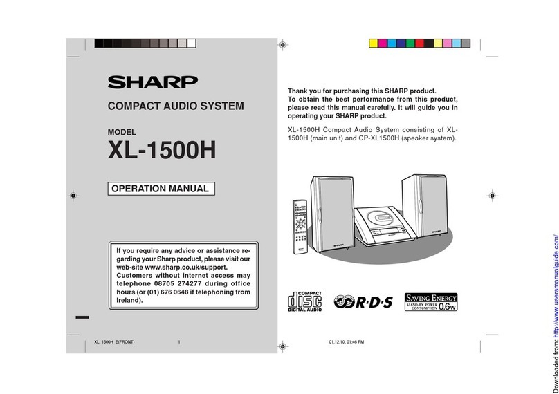
3. To be sure that no shock hazard exists, check for leakage
current in the following manner.
* Plug the AC line cord directly into a 120 volt AC outlet.
* Using two clip leads, connect a 1.5 kohm, 10 watt resistor
paralleled by a 0.15 µF capacitor in series with all exposed
metal cabinet parts and a known earth ground, such as
conduit or electrical ground connected to earth ground.
* Use a VTVM or VOM with 1000 ohm per volt, or higher,
sensitivity to measure the AC voltage drop across the
resistor (See diagram).
* Connect the resistor connection to all exposed metal parts
havingareturnpathtothechassis(antenna,metalcabinet,
screw heads, knobs and control shafts, escutcheon, etc.)
and measure the AC voltage drop across the resistor.
TO EXPOSED
METAL PARTS
CONNECT TO
KNOWN EARTH
GROUND
TEST PROBE
0.15 µF
1.5 kohms
10 W
VTVM
AC SCALE
CD-XP120
General
Amplifier
CD player
Tuner
Cassette deck
Power source AC 120 V, 60 Hz
Power consump-
tion 53 W
Dimensions Width: 10-5/8" (270 mm)
Height: 12" (305 mm)
Depth: 13-1/2" (343 mm)
Weight 12.8 lbs. (5.8 kg)
Output power 20 watts minimum RMS per channel into 8
ohms from 100 Hz to 20 kHz, 10% total har-
monic distortion
Output terminals Speakers: 8 ohms
Headphones: 16 - 50 ohms (recommended:
32 ohms)
Type 3-disc multi-play compact disc player
Signal readout Non-contact, 3-beam semiconductor laser
pickup
D/A converter 1-bit D/A converter
Frequency re-
sponse 20 - 20,000 Hz
Dynamic range 90 dB (1 kHz)
Frequency range FM: 87.5 - 108 MHz
AM: 530 - 1,720 kHz
Frequency re-
sponse 125 - 8,000 Hz (Normal tape)
Signal/noise ratio 50 dB (TAPE 1, recording/playback)
50 dB (TAPE 2, playback)
Wow and flutter 0.3 % (WRMS)
Type 2-way type speaker system
Tweeter
4" (10 cm) Woofer
Maximum input
power 40 W
Rated input power 20 W
Impedance 8 ohms
Dimensions Width: 7-7/8" (200 mm)
Height: 12" (305 mm)
Depth: 6-9/16" (167 mm)
Weight 4.6 lbs. (2.1 kg)/each
AllcheckmustberepeatedwiththeAClinecordplugconnection
reversed.
Anyreading of0.3 voltRMS (thiscorresponds to0.2 milliamp.
AC.) or more is excessive and indicates a potential shock
hazard which must be corrected before returning the audio
product to the owner.
All manuals and user guides at all-guides.com

– 3 –
CD-XP120
NAMES OF PARTS
CD-XP120
Front panel
1. Disc Tray
2. Power On/Stand-by Button
3. Tuner (Band) Button
4. CD Button
5. CD Track Down or Fast Reverse,
Tuner Preset Down Button
6. Headphone Jack
7. CD Stop Button
8. CD Play or Repeat Button
9. Tuning Down Button
10. Tuning Up Button
11. Tape 1 Cassette Compartment
12. Tape Button
13. CD Track Up or Fast Forward,
Tuner Preset Up Button
14. Equalizer Mode Select/Extra Bass/
Demo Mode Button
15. Disc Tray Open/Close Button
16. Disc Skip Button
17. Volume Up and Down Buttons
18. Tape 2 Cassette Compartment
19. Tape 1 Record Button
20. Tape 1 Play Button
21. Tape 1 Rewind Button
22. Tape 1 Fast Forward Button
23. Tape 1 Stop/Eject Button
24. Tape 1 Pause Button
25. Tape 2 Play Button
26. Tape 2 Rewind Button
27. Tape 2 Fast Forward Button
28. Tape 2 Stop/Eject Button
2
1
3
12
13
14
15
16
17
4
5
6
7
8
11
19
9
18
10
20 21 22 23 24 25 26 27 28
Display
1. CD Play Indicator
2. CD Repeat Play Indicator
3. FM Station Indicator
4. AM Station Indicator
5. Disc Number Indicators
6. Clock Indicator
7. Sleep Indicator
8. Timer Play Indicator
9. Tape 1 Record Indicator
10. CD Pause Indicator
11. FM Stereo Mode Indicator
12. FM Stereo Receiving Indicator
13. Memory Indicator
14. Random Play Indicator
15. Extra Bass Indicator
Rear panel
1. AC Power Input Jack
2. Transport Screw
3. FM/AM Loop Antenna Jack
4. Speaker Terminals
2
1
3
4
1 2 3 4 11 12
13
14
7 9 10 15
6
5
8
All manuals and user guides at all-guides.com

CD-XP120
– 4 –
CD-XP120
CP-XP120
1. Tweeter
2. Woofer
3. Bass Reflex Duct
4. Speaker Wire
4
3
1
2
Remote control
1. Remote Control Transmitter
2. Disc Number Select Buttons
3. CD Pause Button
4. Memory/Set Button
5. Clear Button
6. CD Random Button
7. Clock Button
8. Equalizer Mode Select Button
9. Tuner (Band) Button
10. CD Button
11. Power On/Stand-by Button
12. Extra Bass Button
13. CD Stop Button
14. CD Play or Repeat Button
15. CD Track Up or Fast Forward,
Tuner Preset Up Button
16. CD Track Down or Fast Reverse,
Tuner Preset Down Button
17. Timer Button
18. Sleep Button
19. Tape Button
20. Volume Up and Down Buttons
1
2
3
4
6
7
8
9
10
11
12
15
16
17
18
19
20
13
14
5
Buttons with " " mark in the illustration can be operated on the re-
mote control only.
All manuals and user guides at all-guides.com

– 5 –
CD-XP120
DISASSEMBLY
Caution on Disassembly
Follow the below-mentioned notes when disassembling
the unit and reassembling it, to keep it safe and ensure
excellent performance:
1. Take cassette tape and compact disc out of the unit.
2. Be sure to remove the power supply plug from the wall
outlet before starting to disassemble the unit.
3.Takeoffnylon bands orwireholderswhere they need to
beremovedwhendisassemblingtheunit.Afterservicing
theunit,besure to rearrange theleadswherethey were
before disassembling.
4. Take sufficient care on static electricity of integrated
circuits and other circuits when servicing.
Figure 5-2
Figure 5-1
Figure 5-3
CD-XP120
1 Top Cabinet 1. Screw ...................... (A1) x4 5-1
2 Side Panel 1. Screw ...................... (B1) x6 5-1
(Left/Right)
3 CD Player Unit 1. Turn on the power supply,.. 5-2
open the disc tray, take out
the CD tray cover, and close.
2. CD Tray Cover........ (C1) x1
3. Hook........................ (C2) x2
4. Socket ..................... (C3) x4 5-3
4 Rear Panel 1. Screw ...................... (D1) x6 5-2
5 Main PWB 1. Screw ...................... (E1) x5 5-2,5-3
2. Socket ..................... (E2) x7 5-3
6 Front Panel 1. Screw .......................(F1) x3 5-3
2. Hook.........................(F2) x2
7 Switch A PWB 1. Screw ...................... (G1) x3 6-1
2. Socket ..................... (G2) x1
8 Display PWB 1. Screw .................... (H1) x10 6-1
9 Tape Mechanism 1. Open the cassette holder. 6-1
2. Screw...................... (J1) x8
10
Headphones PWB
1. Screw ...................... (K1) x1 6-1
11 Turntable 1. Screw .......................(L1) x1 6-2
2. Spacer......................(L2) x1
12 Loading Tray 1.
Push forward the loading tray.
6-2
2.
Inserting the flat head into the
hole, push in the direction indi-
cated by the arrow. ...
(M1) x2
13 CD Servo PWB 1. Screw ...................... (N1) x3 6-3
(Note 1) 2. Socket ..................... (N2) x5
14 Switch B PWB 1. Screw ...................... (P1) x2 6-3
15 CD Mechanism 1. Screw ...................... (Q1) x4 6-4
2. Spring...................... (Q2) x4
STEP REMOVAL PROCEDURE FIGURE
Note 1:
1. After removing the connector for the optical pickup from the
connector,wraptheconductivealuminiumfoilaroundthefrontend
of the connector so as to protect the optical pickup from electro-
static damage.
CD-XP120
Rear
Panel
Side Panel
(Right)
Side Panel
(Left)
Top Cabinet
Front
Panel
(A1)x2
ø3x16mm
(A1)x2
ø3x16mm
(B1)x2
ø3x10mm
(B1)x2
ø3x10mm
(B1)x2
ø3x8mm
CD Player
Unit 1
1
2
2
Main PWB
Rear
Panel
Pull
Pull Front
Panel
(D1)x1
ø3x10mm
(E1)x1
ø3x10mm
(E1)x2
ø3x8mm
(D1)x4
ø3x8mm (D1)x1
ø3x10mm
(C2)x1
(C1)x1
(C2)x1
Front
Panel
Main PWB
Power
PWB
(E2)x2
(E2)x3
(E2)x2
(F2)x1
(F2)x1
(C3)x1
(C3)x3
(F1)x3
ø3x6mm
(E1)x2
ø3x10mm
All manuals and user guides at all-guides.com

CD-XP120
– 6 –
Figure 6-1
Figure 6-2
Figure 6-3
Figure 6-4
(H1)x10
ø2.5x10mm
(J1)x8
ø3x10mm
(K1)x1
ø2.5x10mm
Display PWB
Display PWB
Switch A
PWB
Headphones
PWB
Open
Cassette
Holder
Tape
Mechanism
Front Panel
(G1)x3
ø2.5x10mm
(G2)x1
(L2)x1
(M1)x1
(M1)x1
(L1)x1
ø3x8mm
Screwdriver
Screwdriver
Turntable
Loading Tray
(N2)x1
(N2)x2
(N2)x1
(N2)x1
(N1)x3
ø3x24mm
CD Servo
PWB
Switch B
PWB
Loading
Tray
(P1)x2
ø3x8mm
(Q1)x4
ø2.5x8mm
(Q2)x4
CD Mechanism
Loading Tray
CP-XP120
This speaker CP-XP120 is available in assembles only and
may not be disassembled.
All manuals and user guides at all-guides.com
all-guides.com

– 7 –
CD-XP120
REMOVING AND REINSTALLING THE MAIN PARTS
TAPE MECHANISM SECTION
Perform steps 1 to 6 and 9 of the disassembly method to
remove the tape mechanism.
Figure 7-1
Figure 7-2
Figure 7-3
Figure 7-4Figure 7-5
How to remove the record/playback and erase
heads (TAPE 1) (See Fig. 7-1)
1. When you remove the screws (A1) x 2 pcs., the record/
playback head can be removed.
2.Move thehooks(A2)x2pcs.,toward thecenterpositionas
shown in Fig. 7-1 and then lift the erase head.
How to remove the playback head (TAPE 2)
(See Fig. 7-2)
1. When you remove the screws (B1) x 2 pcs., the playback
head can be removed.
How to remove the pinch roller (TAPE 1)
(See Fig. 7-3)
1. When you remove the screw (C1) x 1 pc., the pinch roller
can be removed.
Note:
When installing the pinch roller, pay attention to the spring
mounting position.
How to remove the pinch roller (TAPE 2)
(See Fig. 7-3)
1. When you remove the screw (D1) x 1 pc., the pinch roller
can be removed.
Note:
When installing the pinch roller, pay attention to the spring
mounting position.
How to remove the motor (See Fig. 7-4)
1. Remove the belt.
2. Remove the screws (E1) x 6 pcs., to remove the motor
bracket.
3. Remove the screws (E2) x 3 pcs., to remove the motor.
How to remove the belt (TAPE 1)
(See Fig. 7-5)
1. Remove the main belt (F1) x 1 pc., from the motor side.
2. Remove the FF/REW belt (F2) x 1 pc.
How to remove the belt (TAPE 2)
(See Fig. 7-5)
1. Remove the main belt (G1) x 1 pc., from the motor side.
2. Remove the FF/REW belt (G2) x 1 pc.
Record/Playback
Head
Erase
Head
(A1)x1
ø2x3mm
(A1)x1
ø2x7mm
Hook
(A2)x2
TAPE 1
TAPE 2
(B1)x1
ø2x6mm
(B1)x1
ø2x6mm Playback
Head
TAPE 2
Pinch Roller
TAPE 1
Pinch Roller
(C1)x1
ø2x4mm (D1)x1
ø2x4mm
Motor
(E2)x3
Special Screw
Motor
Bracket
(E1)x2
ø2x4mm
(E1)x2
ø2x4mm
(E1)x2
ø2x4mm
Motor
Motor
Bracket
TAPE 2
TAPE 1
TAPE 2
Main Belt
(G1)x1 TAPE 1
Main Belt
(F1)x1
Motor
Motor
REW/FF
Clutch Ass'y
REW/FF
Clutch Ass'y
Main
Belt
(F1)x1
Main
Belt
(G1)x1
REW/FF
Belt
(G2)x1
REW/FF
Belt
(F2)x1
All manuals and user guides at all-guides.com

CD-XP120
– 8 –
How to remove the pickup (See Fig. 8-3)
1. Remove the stop washer (C1) x 1 pc., to remove the gear
(C2) x 1 pc.
2. Remove the screws (C3) x 2 pcs., to remove the shaft
(C4) x 1 pc.
3. Remove the pickup.
Note
After removing the connector for the optical pickup from the
connectorwraptheconductivealuminiumfoilaroundthefront
end of connector so as to protect the optical pickup from
electrostatic damage.
Figure 8-2
CD MECHANISM SECTION
Perform steps 1, 2, 3, 11, 12, 13 and 15 of the disassembly
method to remove the CD mechanism.
How to remove the loading motor
(See Figs. 8-1, 8-2)
1. Remove the screws (B1) x 5 pcs.
2. Remove the belt (B2) x 1 pc.
3. Remove the screws (B3) x 2 pcs., to remove the loading
motor.
Figure 8-1
(B1)x2
ø3x8mm
(A1)x4
ø3x8mm
(B1)x3
ø3x8mm
Loading
Tray
(B3)x2
ø2.4x3mm
(B2)x1
(A2)x1
Loading
Motor
T/T Up/Down
Motor
(A3)x2
ø2.4x3mm
Figure 8-3
How to remove the T/T up/down motor
(See Figs. 8-1, 8-2)
1. Remove the screws (A1) x 4 pcs.
2. Remove the belt (A2) x 1 pc.
3. Remove the screws (A3) x 2 pcs., to remove the T/T up/
down motor.
(C3)x1
ø2.6x6mm
CD
Mechanism
Stop Washer
(C1)x1
Gear
(C2)x1
Shaft
(C4)x1
Pickup
(C3)x1
ø2.6x6mm
All manuals and user guides at all-guides.com

– 9 –
CD-XP120
Test Stage Frequency Frequency
Display Setting/
Adjusting
Parts
Instrument
Connection
• AM IF/RF
Signal generator: 400 Hz, 30%, AM modulated
*1. Input: Antenna Output: TP302
*2. Input: Antenna Output: TP301
TUNER SECTION
fL: Low-range frequency
fH: High-range frequency
AM IF 450 kHz 1,720 kHz T351 *1
AM Band — 530 kHz (fL): T306 *2
Coverage 1.1 ±0.1 V
AM Tracking 990 kHz 990 kHz (fL): T302 *1
*1. Input: Antenna Output: TP301
*2. Input: Antenna Output: Speaker Terminal
•FM RF
Signal generator: 1 kHz, 40 kHz dev., FM modulated
FM Band — 87.50 MHz L303 (fL): *1
Coverage 1.3 V ±0.1 V
FM RF 98.00 MHz 98.00 MHz L302 *2
(10-30 dB)
Test Stage Instrument
Connection
Frequency Frequency
Display Setting/
Adjusting
Point
Figure 9-2 ADJUSTMENT POINTS
•FM IF
Signal generator: 10.7 MHz, FM modulated
IF 10.7 MHz 98 MHz T304 *1
(Turn the
core of trans-
former T304
fully counter-
clock wise)
Test Stage Instrument
Connection
Frequency Frequency
Display Setting/
Adjusting
Point
*1. Input: Antenna Output: TP301
ADJUSTMENT
MECHANISM SECTION
•Driving Force Check
Torque Meter Specified Value
Play: TW-2111 Tape 1: Over 80 g
Tape 2: Over 80 g
•Torque Check
Torque Meter
Tape 2
Play: TW-2111 30 to 80 g.cm 30 to 80 g.cm
Fast forward: TW-2231 — 70 to 180 g.cm
Rewind: TW-2231 — 70 to 180 g.cm
Specified Value
Tape 1
Specified
Value
Adjusting
Point Instrument
Connection
Test Tape
Tape MTT-111 Variable 3,000 ±30 Hz Speaker
speed Resistor in Terminal
motor. (Load
resistance:
6 ohms)
•Tape Speed
Figure 9-1
TAPE MECHANISM
Tape
Motor
Variable Resistor in motor
FM IF
FM RF
VR351
FM MUTE
Level
T351
AM IF
T302
T306
T304
IC301
IC302
L303
L302
CNP301
FM BAND
COVERAGE fL
AM BAND
COVERAGE fL
AM TRACKING
fL
MAIN PWB
1
1
11 12
22
20
R381
R356
R357
TP301
TP302
Adjusting
Parts
Display
Frequency
• FM Mute Level (FM ST MODE)
Signal generator: 1 kHz, 40 kHz dev., FM modulated
*1. Adjust so that an output signal appears.
98.00 MHz 98.00 MHz VR351*1 Input:CNP301
(26 dBµV) Output: Speaker
Terminal
Instrument
Connection
All manuals and user guides at all-guides.com

CD-XP120
– 10 –
TEST MODE
PLAY + DISC SKIP test04 TIMER ON/OFF TEST MODE
FL DISPLAY:
STOP + DISC SKIP test05 VFD DISPLAY WINDOW TEST MODE
FL DISPLAY: VFD ALL LIGHT
FUNCTION: TEST THE VFD DISPLAY WINDOW
PLAY + OPEN/CLOSE test08 OPEN/CLOSE & 3 DISC CHANGER AGING TEST
DISPLAY:
FUNCTION: Enter the TEST MODE 8, MCU control the 3 DISC CHANGER OPEN/CLOSE.
After open finished, tray rotate 1 circle (360 degree). Then close, After close
finished, tray rotate 1 circle (360 degree) again.
Request: Every period include 4 operation. Below is TIMING:
Enter test mode
CHANGER
Find the disc 1 position
open
delay 3S after open finish
rotate 1 circle
close
delay 3S after close finish
rotate 1 circle
All manuals and user guides at all-guides.com

– 11 –
CD-XP120
PLAY + VOLUME DOWN test06 FRONT PANEL KEY TEST
FL DISPLAY:
FUNCTION:
FUNCTION:
FRONT PANELKEYTEST MODE,IF ALL KEYHAVEBEENPRESSED 1 TIME,
THEN
PRESS THE "POWER" KEY, VFD DISPLAY "OK".
PLAY + VOLUME UP test03 VOLUME TEST MODE
FL DISPLAY:
1. TEST 3 DISPLAY 1 SECOND. THEN CHANGE TO CD FUNCTION.
2. IN CD FUNCTION (Pickup IN CHECK DISC1 SW TOC_IL No
DISC RECEIVE OPEN/CLOSE KEY OPEN RECEIVE
OPEN/CLOSE KEY CLOSE)
3. Can change to other function [TAPE/TUNER] FUNCTION KEY PROCESS
SAME AS NORMAL PROCESS.
4. In any function within this test mode VOLUME CONTROL HAS
3LEVEL [0/23/MAX] CANCEL VOL UP/DOWN CONTINUE PROCESS
FUNCTION.
PLAY + TUNER test02 TUNER TEST MODE
FL DISPLAY
FUNCTION STORE 10 PRESET TUNER IN THE MEMORY [AM/FM ST]
FM test use the BAND key change from FM ST.
All manuals and user guides at all-guides.com
all-guides.com

CD-XP120
– 12 –
Figure 12 BLOCK DIAGRAM (1/4)
1 2 3 4 5 6 7 8 9
10 11 12 13 14
1516171819
202122232425262728
32 31 30 29 28 27 26 25 24 23 22 21 20 19 18 17
123456789
10 11 12 13 14 15 16
LOAD+
LOAD–
ROTATE
PICK_IN
DISC_SW
LOAD_SW
O/C SW
–
+
–
+
PO1–
PO1+
VO3–
VO3+
VIN3
VG3
VCC
VCC
BIAS
VG4
VIN4
VO4+
VO4–
OPO
VO2–
VO2+
VIN2
VG2
GND
GND
GND
MUTE
REG O
TRB
VG1
VIN1
VO1+
VO1–
VREF
VDET
TEBPF
TEOUT
TEN
FEN
FEOUT
GCTL
FBAL
TBAL
E
F
D
B
C
A
GND
NRFDET
OFTR
CBDO
CDFTR
BDO
3TOUT
CEA
ARF
CACC
RFIN
RFOUT
RFN
VCC
LD
PD
M
M
UP_SW
DISC_SW
LOAD SW
M_GND
ROTATE-
ROTATE+
M+
M–
C
TR–
+5V
1/2V
E
A
B
F
C
GND
PD
VR
LD
FO–
FO+
TR+
ACTUATOR
FO–
TR–
TR+
FO+
–
+
–
+
–
+
–
+
–
+
VCC
LD
MON
GND
E
A
B
F
+
+
–
–
SP+
SP–
SL+
SL–
PU-IN
GND
M
M
PICKUP UNIT
SW1
OPEN/
CLOSE
SW2
DISC
SW3
UP
M3
T/T UP/DOWN
LOADING MOTOR Q403
Q402
Q405
Q407
Q406
Q408
Q409
Q410
D403
IC402
AN22000A
HEAD AMP.
Q401
Q404
IC404
MM1469XH
FOCUS/TRACKING/SPIN/SLED DRIVER
D402
NM802
SPINDLE
MOTOR
NM801
SLED
MOTOR
M1
CD LOADING
MOTOR
SW4
PICKUP IN
IC404
LASER
DRIVER
All manuals and user guides at all-guides.com

– 13 –
CD-XP120
Figure 13 BLOCK DIAGRAM (2/4)
48
47
46
45
44
43
42
41
40
39
38
37 24
23
22
21
20
19
18
17
16
15
14
13
80
79
78
77
76
75
74
73
72
71
70
69
68
67
66
65
64
63
62
61
40
39
38
37
36
35
34
33
32
31
30
29
28
27
26
25
24
23
22
21
20 19 18 17 16 15 14 13 12 11 10 9 8 7 6 5 4 3 2 1
50 51 52 53 54 55 56 57 58 59 60
41 42 43 44 45 46 47 48 49
36 35 34 33 32 31 30 29 28 27 26 25
1 2 3 4 5 6 7 8 9
10 11 12
TAPE_DET
TAPE_DET
DEMO
MMOD
NRST
BLKCK
DO
E
GVSW
SYS_STOP
MODE_CHK
A_GND
CD_R
CD_L
DATA
MLD
MDATA MCLK
FM_ST
SD
P_STB
P_MUTE
STB
CLK
P_CON
CD_STB
CD+B
IR
CE
DI
CL
P0W_KEY
XO
XI
VSS
OSC1
OSC2 VDD
ROTATE
LOAD-
LOAD+
UP_SW
DISC_SW
LOAD_SW
PICK_IN
STAT
MRST
SSEL
MSEL
PSEL
CSEL
RSEL
OUTR
AVSS1
OUTL
AVDD1
/TEST
IOSEL
RESY
DEMPH
CRC
CLVS
FLAG
IPFLAG
FCLK
CLOCK
BYTCK
VDD
X2
X1
VSS
SBCK
SUBC
VCDF2
PCK
EFM/CK384
AVSS2
AVDD2
VCOF
PLLF
DSLF
DRF
IREF
ARF
WVEL
TDFS
PLLF1
TBAL
LD
BDO
/RFDET
TRCRS
OFT
VDET
RFENV
TE
FE
FBAL
VREF
FOO
TRO
KICK
ECS
ECM
PC
TVD
TVR
PMCK
/RST
STAT
DMUTE
SUBQ
SQCK
BLKCK
/TLOCK
/FLOCK
SENSE
MLD
MDATA
MCLK
TX
DVSS1
DVDD1
SRDATA
LRCK
BCLK
3
2
1
1
2
SD
FM_ST
DO
CL
DI
CE
7
6
3
4
5
9
8
10
1
2
CD+B
STB
CLK
POW_SW
INTR
D_GND
DATA
346127564312
5.6V
P_MUTE
P_STB
6.2V
M_GND
CHANEL_SW
D_GND
5
CNP701 +B2 +B6
+B5
X402
8 MHz
CNS701 CNS101
D401 D405
D404
Q411
Q412
CONSTANT
VOLTAGE
Q413
ZD401
CNS105
CNP105
TO MAIN
SECTION
CNP103
TO MAIN
SECTION
IC401
MN6627482W
CD SIGNAL CONTROL
IC403
IX0051SJ
SYSTEM
MICROCOMPUTER
CNS103
All manuals and user guides at all-guides.com

CD-XP120
– 14 –
Figure 14 BLOCK DIAGRAM (3/4)
CL
CE
DI
SYSTEM
MUTE
Q203
Q204
DO
CL
DI
CE
MO/ST
SWITCHING
+B4
FM/AM
IC302
LC72131
PLL(TUNER)
FM/AM
OUT
+B4
L
R
P.B.
REC
AC BIAS
L
L
R
R
R
L
TAPE
TUNER
CD
PB
CNP103
FROM
CD SECTION
CNS103
ERASE
HEAD
OSC
BIAS
Q801
L801
TAPE 1
PLAYBACK
HEAD
TAPE 2
R-CH
L-CH
R-CH
L-CH
IC601
LC75341M
AUDIO PROCESSOR
P.B
+B4
R
L
R
L REC
L NF
R NF
ALC
REC
T1/T2
REF
R REC
L REC
R NF
L NF
SWITCHING L(T2)
R(T2)
R(T1)
L(T1)
IC801
AN7345K
PLAYBACK AND RECORD
/PLAYBACK AMP.
R
L
FM/AM
MPXIN
STEREO
AM RF IN
AM OSC IN
FM
SP DET
Q360
VT
FM OSC
OSC BUFF
OSC
X352
4.5 MHz
AM BAND
COVERAGE
AM TRACKING
T302
Q302
X351
456 kHz
MO/ST
VCO
FM
DET
VCC
GND
AM IF
CF351
DZ5.1BSJ
AM IF
IC303
LA1832S
IC303
LA1832S
FM IF DET./
FM MPX./AM IF
AM MIX
CF352
T351
FM RF
FM
OSC
L302
CF303
T302
FM IF
IC301
TA7358AP
FM FRONT END
BF301
CNP301
FM
ANTENNA
AM LOOP
ANTENNA
22
3
21
4
24
2
1
8 18
17
3
910
18
11
3
15
10
7
23
14
12
13
1
2
20
19
7
18
10
8
17
13
21
4
5
2
24
23
6
9
16
14
12
15
1
5
13
8
4
3
2
1
3
2
1
21
7
98
5
6
21
2
1
20 22 11
17
1615
9
6
57
13
14
12
15
16
23
4
7
SW801
H
SW801
B, C, D,
F, G SW801
A, E
+B4
FM
4
T306
L303 17
F
R
S
E
C
+B3
+B3
+B3
+B3
M
M2
TAPE
MOTOR
SW5
T1 PLAY
SW6
T1 FF/REW
SW7
T2 FF/REW
SW8
T2 PLAY
CF302
RECORD/
PLAYBACKHEAD
B.P.F
All manuals and user guides at all-guides.com

– 15 –
CD-XP120
Figure 15 BLOCK DIAGRAM (4/4)
T101
POWER TRANSFORMER
6.2 V
-30 V
SO102
SPEAKER
TERMINAL
+B2
+B2
+B4
VDD
VEE
VDD
R-OUT
L-OUT
VF2
VF1
M10 V
+B6
-B2
+B5
+B3
+B1
–B1
~
~
Q103
SYSTEM
MUTE
Q203
Q204
DIN
STB
CLK
+B4
D112~D115
D108~D111
F103
1.6A/125V
F101
3.15A/125V
F102
3.15A/125V
~~
VccB
VccA
Vee
IC201
LM1876TF
POWER AMP.
VDD
KEY1
KEY3
KEY
SW702~SW715
FROM CD
SECTION
AC POWER
SUPPLY CORD
AC 120 V,60 Hz
IC701
SC16312
SYSTEM
MICROCOMPUTER
FL701
FL DISPLAY
~
~
11
15
13
87
3332
30
31
29
18
10
26
15
13
10
46
14
68
37
5251
38
3
2
1
A12 V
+B4
5.6 V
+B2
IC101
MC7805CT
VOLTAGE
REGULATOR
Q104
24
30
-B2
27
5
4
3
1
2
6
9
9
L
R
JK101
HEADPHONES
CNP105
SP DET
CNP702
CNS105
FROM CD
SECTION
CNS702
Q101
Q109,Q110
Q105,Q106
5
4
3
1
2
6
SW701
VOLTAGE
REGULATOR
VOLTAGE REGULATOR
VOLTAGE REGULATOR
VOLTAGE REGULATOR VOLTAGE
REGULATOR
All manuals and user guides at all-guides.com

CD-XP120
– 16 –
Figure 16 SCHEMATIC DIAGRAM (1/10)
A
B
C
D
E
F
G
H
123456
• NOTES ON SCHEMATIC DIAGRAM can be found on page 34.
13V
20V
11.7V
20V
20V
12.3V
11.7V
3 2 1
31
2
1 2 3 4 5
1 2 3 4 5 6 7 8 9
10 7 6 5 4 3 2 1
A_GND
–B1
A 12V
CD_R
CD_L
–30V
5.6V
3.8V
3.8V
D_GND
VF1
VF2
+B1
+B2
M_GND
CD_6.2V
–B1
+B1
A_GND
A_GND1
7
6
4
3
5
8
6
5
7
4
3
7
6
5
4
3
1
21
21
SD
FM ST
DO
CL
DI
CE
A_12V
D_GND
TUN_R
TUN_L
A_GND
2
10
9
6
8
11
4
5
7
3
1
FM ST
SD
DO
CL
DI
CE
CD+B
TAPE_DET
D_GND
CHANEL_SW
M_GND
CD_6.2V
STB
MUTE
5V
2
P23 12 - C
FROM
CD SERVO PWB
P23 9 - A
FROM
CD SERVO PWB
P23 12 - D
FROM
CD SERVO PWB
P21 12 - D, E
TO TUNER SECTION
1
23 1
23
CNS102
P25 12 - G
FROM DISPLAY PWB
1
12
3
32
POWER PWB-A3
+B
+B +B
+B
+B
+B
+B
+B
+B
+B
+B
+B
+B
+B
+B
+B
+B
+B
+B
+B +B
+B
-B
-B
AC POWER
SUPPLY CORD
VLTAGE
REGULATOR
Q103, Q104: VOLTAGE REGULATOR
Q105, Q106, Q109, Q110: VOLTAGE REGULATOR
CNP105
CNS105 CNS101 CNS103
CNP101
C142
0.022
C141
100/16
R129
10
CNP103
IC101
MC7805CT
VOLTAGE
REGULATOR
Q104
2SD2012 Y
CNP102
D119
1N4004
R133
1.2K
D117
1N4004
Q111
KRC107 M
R107
1.2K
Q112
KRA102 M
D116
1N4004
D105
1N4004
C143
220/25
Q103
2SD2012 Y
R109
47
R110
47
C124
47/25
C123
0.047
R113
22K
C115
0.022
C119
10/16
ZD103
DZ13BSA
C116
0.022
Q102
HSC1609 GR
R108
100
C113
100/25
D104
1N4148
R111
4.7K
R114
22K
C111
100/25
R106
330
R101
22K
C109
330/35
ZD101
DZ30BSB
R104
12K
ZD102
DZ6.2BSA
C108
47/50
Q101
KSA1015 GR
C107
220/50
C102
100/50
D101
1N4004
D102
1N4004
C110
100/35
R105
330
R102
10
R103
47K
C101
100/50
D103
1N4004
C103
0.1
C104
0.1
D108
1N5402M
D111
1N5402M
D109
1N5402M
D110
1N5402M
D114
1N4004
D112
1N4004
D115
1N4004
C105
0.1
C106
0.1
D113
1N4004
F101
3.15A/125V
F102
3.15A/125V
F103
1.6A/125V
CNP104
CNS104
BI104
T101
POWER
TRANSFORMER
R121
4.7M
SO101
AC INLET
AC 120 V, 60 Hz
C117
2200/35
C118
2200/35
C121
0.022
R118
22K
C122
470/16
D107
1N4004
Q106
2SD2012 Y
Q105
HSC1609 GR
R124
820
Q110
KRC107 M
Q109
KRA102 M
C112
4700/35
C114
470/25
R115
100
C120
100/25
R117
4.7K
R116
47
ZD104
DZ8.2BSC
D106
1N4148
FM SIGNAL
PLAYBACK SIGNAL
RECORD SIGNAL
CD SIGNAL
All manuals and user guides at all-guides.com
all-guides.com

– 17 –
CD-XP120
Figure 17 SCHEMATIC DIAGRAM (2/10)
78 9 10 11 12
31
15 14 13 12 11 10 9 8 7 6 5 4 123
2
12 11 10 9 8 7 6 5 4 3 2 1
13 14 15 16 17 18 19 20 21 22 23 24
R
L
TAPE_DET
M_10V
HEADPHONES PWB-A4
R OUT
L OUT
A_GND
R IN
L IN
A_GND
CHANEL_SW
TAPE L
TAPE R
REC R
REC L
+10V
R OUT
L OUT
A_GND
R IN
L IN
TAPE R
M_GND
CD_6.2V
–B
+B
L
R
CL
VDD
VREF
ROUT
RBS
RTRE
RIN
RSL0
R4
R3
R2
R1 L1
L2
L3
L4
LSL0
LIN
LTRE
LOUT
VSS
CE
DI
CE
DI
CL
TUN L
CD L
CD R
TUN R
TAPE L
M_GND
P19 12 - A, B
TO TAPE SECTION
LBS
OUT B
OUT A
VCC A
VCC B
+IN B
–IN B
–IN A
+IN A
MUTE A
MUTE B
GND B
GND A
STB A
STB B
VEE
1
2
3
4
5
7 2 14 3568910
1
2
3
4
5
1
2
3
4
5
–
–
+
+
MAIN PWB-A1(1/3)
B
SYSTEM
MUTE
SYSTEM
MUTE
+B
+B +B
+B
+B
+B
+B +B
+B
+B
+B
+B
+B
+B
+B
+B
-B
-B -B
-B
O
R
V
OLTAGE REGULATOR
L-ch
R-ch
BI108CNS108
CNP108
L103
10 µH
R128
390
R127
390
JK101
HEADPHONES
SO102
SPEAKER
TERMINAL
R122
10
L102
3 µH
C128
0.1
R120
4.7
C126
0.1
R119
4.7
C127
0.1
C125
0.1
C134
0.0047 C133
0.0047
L101
3 µH
R123
10
R622
100K
C620
220P
C619
220P
C621
220P
C616
0.47/16
R609
1K
R605
1K
R607
1K
C612
0.0027 C610
2.2/50
C617
33/16
C608
4.7/50
C618
100/16
R611
47K
R615
10K
R613
3.9K
C614
0.1(ML)
IC601
LC75341M
AUDIO
PROCESSOR
C601 10/16
C602 10/16
C603 10/16
R625
7.5K
R624
7.5K
R620
560
R618
33K
R616
33K
C606 10/16
C604 10/16
C605 10/16
R610
47K
C609
2.2/50
R612
3.9K
C613
0.1(ML)
C622
0.1
C623
0.1
C615
0.47/16
R608
1K
R606
1K
R604
1K
C607
4.7/50
R614
10K
C611
0.0027
R623
100K
R603 1K
R602 1K
R601 1K
R617
33K R621
560
R619
33K
C
NP103
D602
1N4004
D603
1N4004
D601
1N4004
R202
1K
R201
1K
IC201
LM1876TF
POWER AMP.
C203
47/50
R206
100K
R205
100K
R204
1K
C204
47/50
C202
47/50
R213
100K
R214
100K
R203
1K
C201
47/50
C205
100/16
ZD203
DZ3.3BSB
C207
47/25
R219
10K
R218
10K
Q203
KSC1815 GR
Q204
KSC1815 GR
R209
10K
R215
4.7K
R210
10K
R217
10K
Q202
HSC1609 GR
R220
4.7K
R221
47K
C208
470/16
ZD204
DZ3.3BSB
ZD201
DZ3.3BSB
R216
10K
R211
10K
R207
10K Q201
KSC1815 GR
R208
10K
IC101
MC7805CT
VOLTAGE
REGULATOR
D119
1N4004
D117
1N4004
D116
1N4004
D105
1N4004
C143
220/25
C124
47/25
C123
0.047
C119
10/16
2200/35
C121
0.022
R118
22K
C122
470/16
D107
1N4004
Q106
2SD2012 Y
C120
100/25
R117
4.7K
1
16
4
7
ZD104
Z
8.2BSC
D106
1N4148
All manuals and user guides at all-guides.com

CD-XP120
– 18 –
A
B
C
D
E
F
G
H
123456
• NOTES ON SCHEMATIC DIAGRAM can be found on page 34.
Figure 18 SCHEMATIC DIAGRAM (3/10)
24 23 22 21 20 19 18 17 16
1 2 3 4 5 6 7 8 9
R
P
RP
A_GND
T1_L
T1_R
T2_L2
T2_L1
T2_R1
A_GND
T2_R2
L(T1)
R(T2)
L(T2)
L NF R NF
PLO
RRO
RLO
RLI
L NF R NF
R
R
P
P
R
L:T1
H:T2
PLAYBACK HEAD
TAPE 2
TAPE 1
PLAYBACK/RECORD
HEAD
ERASE HERD
+B
–
+ 2 3
2
1
4
3
2
1
4
3
2
1
M
2
1
2
1
3
2
3
4
1
3
4
MAIN PWB-A1(2/3)
1
2
3
1
P
L-CH
R-CH
L-CH
R-CH
R(T1)
PRO
RRI
D806
1N4148
R834
33K
CNP803CNS803
R835
18K
D804
1N4148
CNP804
CNS804
R801
1K
R802
1K
CNP801
C802
560P
C801
560P
C812
0.0027
R808
10K
C819
0.0022
R813
33K
R806
56
R809
100K
C815
0.033
C808
330P
C810
100/25
R815
5.6K
R811
3.9K
C813
560P
C817
47/25
R804
1K
C805
330P
C804
560P
C803
560P
C806
330P
C809
330P
R803
1K
IC801
AN7345K
IC801
PLAYBACK AND
RECORD/PLAYBACK AMP.
C814
560P
R812
3.9K
C818
47/25
R810
100K
C811
100/25
R807
56
C816
0.033
C821
3.3/50
R816
5.6K
C822
R
8
1
9
C820
0.0022
R814
33K
R820
R805
10K
C807
0.0027
R818
68K
R817
39K
D803
1N4148
D802
1N4148
SW801D
REC./P.B.
SW801G
REC./P.B.
SW801B
REC./P.B.
SW801F
REC./P.B.
SW801C
REC./P.B.
CNP802
SW7
TAPE 2
FF/REW
SW6
TAPE 1
FF/REW
SW5
TAPE 1
PLAY
SW8
TAPE 2
PLAY
M2
TAPE
MOTOR
RECORD SINGAL
PLAYBACK SINGAL
All manuals and user guides at all-guides.com

– 19 –
CD-XP120
Figure 19 SCHEMATIC DIAGRAM (4/10)
78 9 10 11 12
2
2 21 20 19 18 17 16 15 14 13
3 4 5 6 7 8 9
10 11 12
M_10V
TAPE_DET
L NF
R
NF
PLO
RRO
RLO
RLI
L NF R NF
VCC
ALC
REF
R
PR
R
P
L:T1
H:T2
P17 8 - A
TO MAIN SECTION
TAPE L
REC L
REC R
+10V
+B
+B
+B
+B
+B +B
+B
A_GND
TAPE R
CHANEL_SW
M_GND
10
9
8
4
5
6
3
2
1
7
B-A1(2/3)
P
PRO
RRI
BIAS OSC.
D806
1N4148
R834
33K R837
1K
R835
18K
8
04
4
148
C812
0.0027
8
08
0K
C819
0.0022
R813
33K
R809
100K
C815
0.033
R815
5.6K
R811
3.9K
C813
560P
C817
47/25
330P
IC801
AN7345K
C814
560P
R812
3.9K
C818
47/25
R810
100K
C816
0.033
C821
3.3/50
R816
5.6K
C822
0.022
C826
22/50
R819
6.8K
C820
0.0022
R814
33K
C828
0.022
R825
100
R827
10K
R820
3.9K
C824
0.001
C830
0.0033
C832
47/25
R822
1.5K
0
5
K
Q801
KSC3203 Y
R833
10
C839
0.0047
(ML)
R831
150
R832
33K
C838
0.022 (ML)
C837
100/10
L801
BIAS OSC.
C836
0.0022
SW801H
REC./P.B.
R830
100
D805
1N4148
R836
8.2K
D801
1N4004
R829
220
SW801E
REC./P.B.
SW801A
REC./P.B.
C834
220/16
C833
22/50
C835
0.022
R818
6.8K
R821
1.5K
R826
10K
C823
0.001
C831
47/25
C829
0.0033
C825
22/50
R824
100
R817
3.9K
C827
0.022
C840
220/16
R823
47K
R828
47K
R838
5.6K
D803
1N4148
All manuals and user guides at all-guides.com

CD-XP120
– 20 –
Figure 20 SCHEMATIC DIAGRAM (5/10)
A
B
C
D
E
F
G
H
123456
• NOTES ON SCHEMATIC DIAGRAM can be found on page 34.
3.8V
4.4V
0V
5.2V
5.2V
5.2V
1.5V
1.5V
0.8V
2
3
2
1
3
2
1
1 2 3 4 5 6 7 8 9
1 2 3
FM
GND
AM
AM OSC.
AM ANTENNA
AM LOOP
ANTENNA
FM
ANTENNA
FM RF
FM IF
OSC BUFF
FM OSC.
FM BAND
COVERAGE fL
13
2
AM BAND
COVERAGE fL
AM TRACKING fL
FM MU
T
LEVE
L
+
+B
+B
+B
+B
VR351
10K(B)
R336
5.6K
R351
5.6K
C
C351
0.022
R309
470
Q306
SSC1674 C
R312
2.2K
R316
330
R314
33
R313
680
C321
0.0033
C316
10/16
R308
10K
C317
0.022
R305
680
C315
100P
R315
33
Q302
SSC1674 C
R304
47K
C311
10P(CH)
C314
22P(CH)
L303
C313
6P
(UJ)
VD302
KDV147B
CF303
R306
33
C312
33P
R307
47
T304
VD303
KDV147B
R303
33K
R302
100K
C318
5P
C319
18P(CH)
BF301
B.P.F
C302
0.001
D302
1N4148
D301
1N4148
T302
C329
0.022
C337
0.022
T306
C335
560P
C334
27P(UJ)
R323
68K
C330
12P(CH)
C332
0.022
C331
0.047
VD301
SVC348S
IC301
TA7358AP
FM FRONT END
C303
0.001
D307
1N4148
D305
1N4148
C304
0.01
D306
1N4148
C306
9P(UJ)
L302
R301
22
C309
0.001
C308
0.022
C307
0.0047
C305
0.0047
CNP301
C349
0.001
C301
0.012
R310
4.7K
FM SIGNAL
AM SIGNAL
All manuals and user guides at all-guides.com
Other manuals for CD-XP120
1
Table of contents
Other Sharp Stereo System manuals

Sharp
Sharp QT-CD700W User manual

Sharp
Sharp XL-70V User manual

Sharp
Sharp WQ-790W User manual

Sharp
Sharp XL-HP404E User manual

Sharp
Sharp CD-ES600 User manual

Sharp
Sharp XL-1200 User manual

Sharp
Sharp XL-S10H User manual

Sharp
Sharp CD-PC3500 User manual

Sharp
Sharp CD-SW300H User manual

Sharp
Sharp CD-C401E User manual

Sharp
Sharp CD-XP300W User manual

Sharp
Sharp XL-HP707 User manual

Sharp
Sharp GX-CD130C User manual

Sharp
Sharp XL-UH12H User manual

Sharp
Sharp XL-DV60 User manual

Sharp
Sharp CD-G20000 User manual

Sharp
Sharp XL-HF201P(BK) User manual

Sharp
Sharp CD-BA2600H User manual

Sharp
Sharp MD-M3H User manual

Sharp
Sharp CD-SW200H User manual