Sharp CD-SW330 User manual

CD-SW330
SERVICE MANUAL
In the interests of user-safety the set should be restored to its
original condition and only parts identical to those specified be
used.
No. S3715CDSW330/
Parts marked with " " are important for maintaining the safety of the set. Be sure to replace these parts with
specified ones for maintaining the safety and performance of the set.
This document has been published to be used
for after sales service only.
The contents are subject to change without notice.
PRECAUTIONS FOR USING LEAD FREE SOLDER
CHAPTER 1. GENERAL DESCRIPTION
[1] Important Service Safety Precaution ........... 1-1
[2] Important Service Notes (For U.S.A only) .... 1-1
[3] Specifications ................................................. 1-2
[4] Names Of Parts ............................................. 1-3
CHAPTER 2. ADJUSTMENTS
[1] Mechanism Section ....................................... 2-1
[2] Test Mode ...................................................... 2-2
[3] CD Section..................................................... 2-4
[4] CD Changer Mechanism Section................... 2-5
CHAPTER 3. MECHANISM BLOCKS
[1] Caution On Disassembly ............................... 3-1
[2] Removing And Reinstalling The Main Parts... 3-4
CHAPTER 4. DIAGRAMS
[1] Main Block Diagrams ..................................... 4-1
[2] CD Block Diagrams ...................................... 4-3
CHAPTER 5. CIRCUIT DESCRIPTION
[1] Waveforms Of Servo Circuit .......................... 5-1
[2] IC Voltage...................................................... 5-2
CHAPTER 6. CIRCUIT SCHEMATICS AND PARTS
LAYOUT
[1] Notes On Schematic Diagram ....................... 6-1
[2] Types Of Transistor And LED........................ 6-1
[3] Schematic Diagram ....................................... 6-2
[4] Wiring Side Of PWB .................................... 6-20
CHAPTER 7. FLOWCHART
[1] Troubleshooting............................................. 7-1
CHAPTER 8. OTHERS
[1] Function Table Of IC...................................... 8-1
[2] FL Display ..................................................... 8-8
Parts Guide
MINI COMPONENT SYSTEM
CD-SW330
MODEL
CD-SW330 Mini Component System consisting of
CD-SW330
(main unit) and CP-S330 (front speaker)
and CP-SW330 (subwoofer).
CONTENTS
XM is the re
g
istered trademark of XM®Satellite Radio Inc.
SHARP CORPORATION

CD-SW330
– i –
AudioXL-MP150Service ManualXLMP150MarketE
PRECAUTIONS FOR USING LEAD-FREE SOLDER
1. Employing lead-free solder
Example:
Indicates lead-free solder of tin,silver and copper.
2. Using lead-free wire solder
When fixing the PWB soldered with the lead-free solder, apply lead-free wire solder. Repairing with conventional lead wire
solder may cause damage or accident due to cracks.
As the melting point of lead-free solder (Sn-Ag-Cu) is higher than the lead wire solder by 40°C, we recommend you to
use a dedicated soldering bit, if you are not familiar with how to obtain lead-free wire solder or soldering bit, contact our
service station or service branch in your area.
3. Soldering
As the melting point of lead-free solder (Sn-Ag-Cu) is about 220°C which is higher than the conventional lead solder
extended period of time. However, since the land may be peeled of for the maximum heat-resistance temperature
of parts may be exceeded, remove the bit from the PWB as soon as you confirm the steady soldering condition.
Lead-free solder contains more tin, and the end of the soldering bit may be easily corrected. Make sure to turn on
and off the power of the bit as required.
If a different type of solder stays on the tip of the soldering bit, it is alloyed with lead-free solder. Clean the bit after
every use of it.
When the tip of the soldering bit is blackened during use, file it with steel wool or fines and paper.
Be careful when replacing parts with polarity indication on the PWB silk.
Lead-free wire solder for servicing
Ref No. Description
Parts No.
PWB-A 92LPWB6809MANS
92LPWB6514LEDS
PWB-C
PWB-D
MAIN (A1), POWER (A2)
PWB-B 92LPWB6809DPLS
92LPWB6809CDUS
DISPLAY (B1), GAME INPUT (B2)
CD MP3
FRONT SPEAKER LED
92LPWB6663XMRS
QPWBF1055AWZZ
92LPWB6230LEDS
PWB-E
PWB-F
PWB-H
XM READY
CD CHANGER MOTOR (PWB ONLY)
SUB WOOFER LED
"MAIN, POWER, DISPLAY, GAME INPUT, CD MP3, FRONT SPEAKER LED, XM READY, CD
CHANGER MOTOR (PWB ONLY), SUB WOOFER LED " of this model employs lead-free solder.
The LF symbol indicates lead-free solder, and is attached on the PWB and service manuals. The alphabetical character
following LF shows the type of lead-free solder.
by 40°C and as it has poor solder wettability, you may be apt to keep the soldering bit in contact with the PWB for

CD-SW330
1 – 1
CHAPTER 1:GENERAL DESCRIPTION
(Fire & Shock Hazard)
Before returning the audio product to the user, perform
the following safety checks.
1. Inspect all lead dress to make certain that leads are not
pinched or that hardware is not lodged between the
chassis and other metal parts in the audio product.
2. Inspect all protective devices such as insulating
materials, cabinet, terminal board, adjustment and
compartment covers or shields, mechanical insulators
etc.
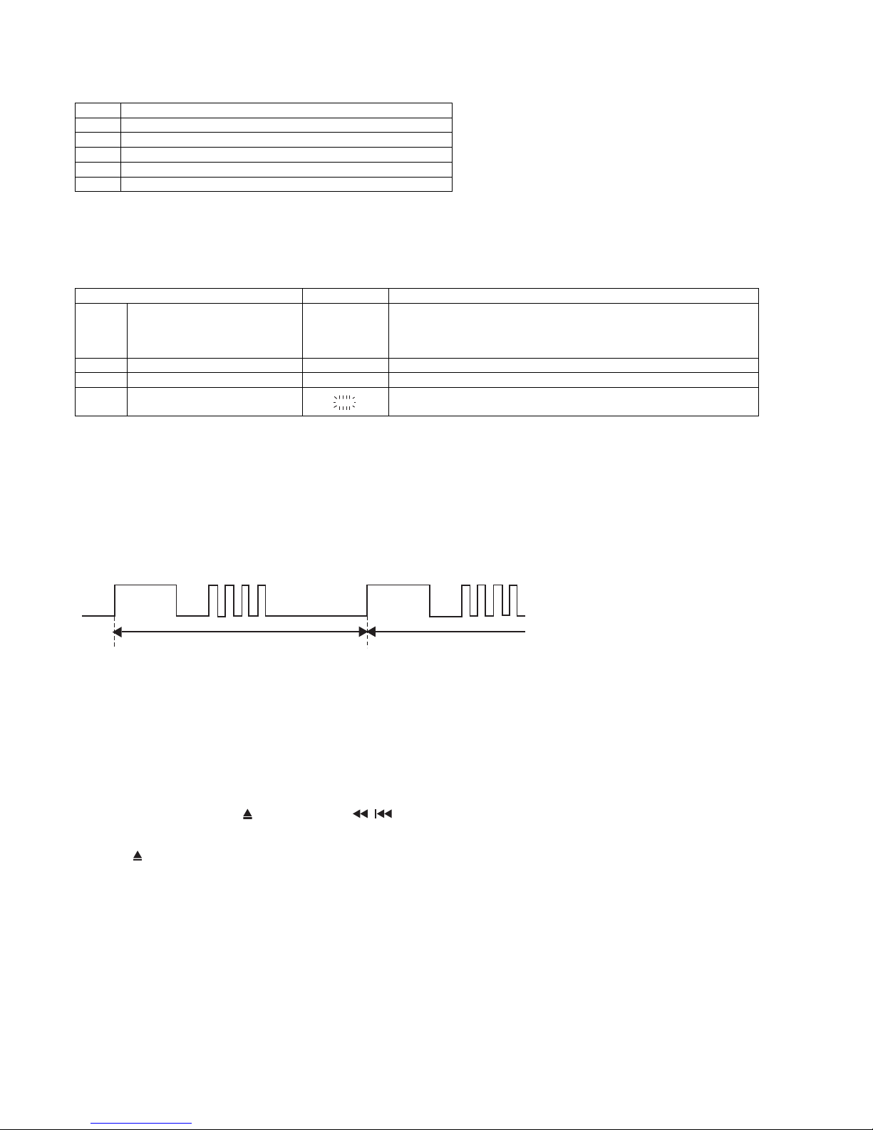
3. To be sure that no shock hazard exists, check for
leakage current in the following manner.
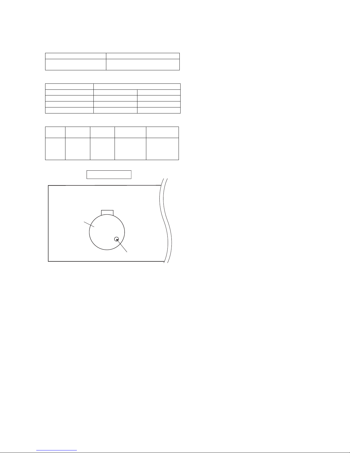
*Plug the AC line cord directly into a 120 volt AC outlet.
* Using two clip leads, connect a 1.5k ohm, 10 watt
resistor paralleled by a 0.15µF capacitor in series
with all exposed metal cabinet parts and a known
earth ground, such as conduit or electrical ground
connected to earth ground.
*Use a VTVM or VOM with 1000 ohm per volt, or
higher, sensitivity to measure the AC voltage drop
across the resistor (See diagram).
* Connect the resistor connection to all exposed metal
parts having a return path to the chassis (antenna,
metal cabinet, screw heads, knobs and control shafts,
escutcheon, etc.) and measure the AC voltage drop
across the resistor.
All check must be repeated with the AC line cord plug
connection reversed.
Any reading of 0.3 volt RMS (this corresponds to 0.2
milliamp. AC.) Or more is excessive and indicates a
potential shock hazard which must be corrected before
returning the audio product to the owner.
[2] Important Service Notes (for U.S.A only)
BEFORE RETURNING THE AUDIO PRODUCT
[1] Important Service Safety Precaution
CAUTION : “These servicing instructions are for use by qualified service personnel only. To reduce
the risk of electric shock do not perform any servicing other than that contained in the operating
instructions unless you are qualified to do so”.
WARNING
1. For continued safety, no modification of any circuit should be
attempted.
2. Disconnect AC power before servicing.
TO EXPOSED
METAL PARTS
CONNECT TO
KNOWN EARTH
GROUND
TEST PROBE
0.15 µ F
1.5k ohms
10W
VTVM
AC SCALE
CAUTION: FOR CONTINUED
PROTECTION AGAINST FIRE
HAZARD, REPLACE ONLY WITH
SAME TYPE F801,F802, 5A,125V/
F803, F804, 2A,125/ F805, 8A,125V FUSES
TYPE F801,F802, 5A,125V/
F803, F804, 2A,125/ F805, 8A,125V
ATTENTION: POUR ASSURER
UNE LONGUE PROTECTION CONTRE
UN INCENDIE, REMPLACER SEULEMENT
PAR UN FUSIBLE DE

CD-SW330
– 3
[3] Specifications
FOR A COMPLETE DESCRIPTION OF THE OPERATION OF THIS UNIT, PLEASE REFER
TO THE OPERATION MANUAL.
As part of our policy of continuous improvement, SHARP reserves
the right to make design and specifcation changes for product
improvement without prior notice.The performance specifcation
figures indicated are nominal values of production units. There may
be some deviations from these values in individual units.
CD-SW330
CP-S330
CP-SW330
General
Amplifier
Power source
AC 120 V, 60 Hz
Power consumption
195 W
Dimensions
Width: 10-1/4" (260 mm)
Height: 13" (330 mm)
Depth: 12-7/8" (323 mm)
Weight
22 lbs. (10 kg)
Output power Front Speakers: 115 watts minimum RMS
per channel into 6 ohms from 100 Hz to 20
KHz, 10% total harmonic distortion.
Subwoofer: 220 watts RMS into 12 ohms
from 50 Hz to 120 Hz, 10% total harmonic
distortion.
Output terminals Front Speakers: 6 ohms
Subwoofer: 12 ohms
Headphones: 16 - 50 ohms
(recommended: 32 ohms)
Video output: 1Vp-p
Input terminals Game/Auxiliary (audio signal):
500 mV/ 47 k ohms
Game/Video: 1Vp-p
CD player
Front Speaker
Subwoofer
Type 5-disc multi-play compact disc player
Signal readout Non-contact, 3-beam semiconductor laser
pickup
D/A converter Multi bit D/A converter
Frequency
response
20 - 20,000 Hz
Dynamic range 90 dB (1 kHz)
Type 3-way type speaker system
Super tweeter
2" (5 cm) tweeter
6-5/16" (16 cm) woofer
Maximum input
power
230 W
Rated input power 115 W
Impedance 6 ohms
Dimensions Width: 7-7/8" (200 mm)
Height: 13" (330 mm)
Depth: 9-1/8" (231 mm)
Weight 7.3 lbs. (3.3 kg)/each
Type Full Range
8" (20 cm) subwoofer
Maximum input
power
440 W
Rated input power 220 W
Impedance 12 ohms
Dimensions Width: 9-13/16" (250 mm)
Height: 13" (330 mm)
Depth: 11-9/16" (294 mm)
Weight 13 lbs. (5.9 kg)
Tuner
Cassette deck
Frequency range FM: 87.5 - 108.0 MHz
AM: 530 - 1,720 kHz
Frequency
response
50 - 14,000 Hz (normal tape)
Signal/noise ratio 55 dB (TAPE 1, playback)
50 dB (TAPE 2, recording/playback)
Wow and flutter 0.3 % (WRMS)
1 – 2

CD-SW330
–2
[4] Names Of Parts
Display
CD-SW330
Front panel
1. Disc Trays
2. Timer Indicator
3. Tuner (Band) Button
4. CD Button
5. Power On/Stand-by Button
6. Tape (1 2) Button
7. Game/Video Button
8. Tape 1 Cassette Compartment
9. Headphone Jack
10. Game/Video Input Jacks
11. Disc Tray Open/Close Button
12. Disc Number Select Buttons
13. Volume Control
14. CD or Tape Stop Button
15. CD Play or Repeat, Tape Play Button
16. CD Track Up or Fast Forward, Tape 2 Fast Forward,
Tuner Preset Up, Time Up Button
17. CD Track Down or Fast Reverse, Tape 2 Fast Rewind,
Tuner Preset Down, Time Down Button
18. Tape 2 Cassette Compartment
19. Remote Sensor
1. Disc Number Indicators
2. MP3/WMA Folder Indicator
3. MP3/WMA Title Indicators
4. MP3 Indicator
5. WMA Indicator
6. Sleep Indicator
7. Timer Play Indicator
8. Timer Recording Indicator
9. Tape 2 Record Indicator
10. Total Indicator
11. Daily Timer Indicator
12. FM Stereo Mode Indicator
13. FM Stereo Receiving Indicator
14. Tape Play Indicator
15. Extra Bass Indicator
16. XM Category Indicator
17. XM Channel Indicator
18. Memory Indicator
19. Disc Repeat Play Indicator
20. Disc Pause Indicator
21. Disc Play Indicator
Rear panel
1. XM Mini-Tuner Jack
2. Cooling Fan
3. AC Power Cord
4. FM 75 Ohms Antenna Jack
5. AM Antenna Ground Terminal
6. AM Loop Antenna Terminal
7. Subwoofer Light-up Jack
8. Speaker Light-up Jacks
9. Video out Jack
10. Subwoofer Terminal
11. Front Speaker Terminals
4
17
8
9
5
6
11
10
3
2
12 3 45 6789
MEMORY
CHAN
CAT X-BASS
11 1213
10 14
1516
17 CHAN
CAT X-BASS
18 19
20 21
MEMORY
1 – 3

CD-SW330
– 3
Remote control
1. Subwoofer
2. Bass Reflex Duct
3. Subwoofer Light-Up Wire
4. Speaker Wire
CD-SW330
CP-S330
CP-SW330
1
2
3
5
6
7
4
9
10
8
11
12
17
19
18
13
15
14
21
20
16
26 27
2928 30
25
24
22 23
1. Remote Control Transmitter
2. Disc Number Select Buttons
3. Clock/Timer Button
4. Character Input/Disc Direct Search Buttons
5. Equalizer Mode Select Button
6. Extra Bass (Surround)/Demo Button
7. Volume Up and Down Buttons
8. Power On/Stand-by Button
9. CD Button
10. Tuner (Band)/XM Button
11. Tape (1 2) Button
12. Game/Video Button
13. Clear/Dimmer Button
14. Disc Random Button
15. Disc Stop Button
16. Tape Stop Button
17. Memory Button
18. Disc Pause Button
19. Disc Play or Repeat Button
20. Tape Play Button
21. Tape 2 Record Pause Button
22. Tuning Up, Cursor Up Button
23. Disc Track Up or Fast Forward, Tape Fast Forward,
Tuner Preset Up, Time Up, Cursor Right Button
24. Disc Track Down or Fast Reverse, Tape Fast Rewind,
Tuner Preset Down, Time Down, Cursor Left Button
25. Tuning Down, Cursor Down Button
26. MP3/WMA Display Button
27. Folder Button
28. XM Menu Button
29. XM Enter Button
30. XM Display Button
Front Speaker
1. Tweeter
2. Super Tweeter
3. Woofer
4. Bass Reflex Duct
5. Speaker Wire
6. Speaker Light-Up Wire
Subwoofer
11
2
3
11
2
4
4
3
56
1 – 4

CD-SW330
2 – 1
CD-ES700/CD-ES77CD-ES700/CD-ES77Service ManualCD-ES700/CD-ES77MarketE
CHAPTER 2. ADJUSTMENTS
[1] Mechanism Section
• Driving Force Check
• Torque Check
• Tape Speed
Figure 1
Torque Meter Specified Value
Play: TW-2111 Tape 1: Over 80 g
Tape 2: Over 80 g
Torque Meter Specified Value
Tape 1 Tape 2
Play: TW-2111 30 to 80 g.cm 30 to 80 g.cm
Fast forward: TW-2231 — 70 to 180 g.cm
— 70 to 180 g.cm
Test Tape Adjust-
ing Point
Specified
Value
Instrument
Connection
Normal
speed
MTT-111 Variable
Resistor in
motor.
3,000 ±30 Hz
Speaker
Speaker Ter-
minal (Load
resistance: 6
ohms)
TAPE MECHANISM
Tape
Motor
Variable Resistor in motor

CD-SW330
2 – 2
[2] Test Mode
•Setting the test mode
During stand-by mode, press GAME/VIDEO button
while pressing down the button and button.
then, press the CD button to enter the test mode.
IL isn’t done
OPEN/CLOSE operation is using manual. IL isn’t done
<< >>,<< >>buttons make pick's slide possible. IL isn’t done
to page 2-3
<<PLAY>> key input.
C D T E S T
A
Do TOC IL. Do normal play.
When these following key is input into PLAY key, track num-
ber can be appoint directly.
<<MEMORY>>
key input.
<< 1>> key: Track 4
<< 2>> key: Track 9
<< 3>> key: Track 15
Adjustment result automatically will
display as below for each 2 sec:
a) "FOF_XXXX"
b) "TOF_XXXX"
c) "TBAL_XX"
d) "TGAN_XX"
f) "FGAN_XX"
g) "RFLS_XX"
––––––––
<<STOP>> key input.
STOP
Explanation:
a) Focus off set = "FOF_XXXX"
b)Tracking off set = "TOF_XXXX"
c)Tracking balance = "TBAL_XX"
d)Tracking Gain = "TGAN_XX"
f) Focus Gain = "FGAN_XX"
g) RF level shift = "RFLS_XX"
VOL — Last memory
P. G E Q — F L AT
X-BASS — OFF
To cancel : Power OFF

CD-SW330
2 – 3
Sliding the PICKUP with<< >>, << >> button
must only be in STOP mode.
<<MEMORY>> key input.
Laser ON.
<<MEMORY>> key input.
Tracking OFF play at that specific point.
<<MEMORY>> key input.
Tracking ON play from that specific point.
<<MEMORY>> key input.
Adjustment result automatically will display as below for each 2 sec :
a) "FOF_XXXX"
b) "TOF_XXXX"
c) "TBAL_XX"
d) "TGAN_XX"
f) "FGAN_XX"
g) "RFLS_XX"
<<STOP>> key input.
STOP
Explanation:
a) Focus off set = "FOF_XXXX"
b)Tracking off set = "TOF_XXXX"
c)Tracking balance = "TBAL_XX"
d)Tracking Gain = "TGAN_XX"
f) Focus Gain = "FGAN_XX"
g) RF level shift = "RFLS_XX"
VOL — Last memory
P. G E Q — F L AT
X-BASS — OFF
To cancel : Power OFF
A

CD-SW330
2 – 4
[3] CD Section
CD Error code description
* 'CHECKING'
If Error is detected, 'CHECKING' will be displayed instead of 'ER-CD**'. 'ER-CD**' display will only be displayed
when error had been detected for the 5th times.
Standard Specification of Stereo System Error Message Display Contents
(*) CHECKING:
If CD changer mechanism error is detected, 'CHECKING' will be display instead of 'ER-CD**'. 'ER-CD**' display will
only be display when error had been detected for the 5th times.
Speaker abnormal detection and +B PROTECTION display
In case speaker abnormal detection or +B PROTECTION had occurred, the unit will automatically enter to stand - by
mode and Timer indicator will be flashing as below.
+B PROTECTION is condition when irregular process occur on power supply line.
BEFORE TRANSPORTING THE UNIT
The following process need to be taken after set tapering/parts replacement.
1. Press the ON/STAND-BY button to enter stand-by mode.
2. While pressing down the button and the button, press the GAME/VIDEO button. The Micro Computer
version number will be displayed as "CM*****".
3. Press button until "WAIT"→"FINISHED" appears.
4. Unplug the AC cord and the unit is ready for transporting.
Error Explanation
10* CAM error. Can't detect CAM switch when CAM is moving.
11* When it detect cam operation error during initialize process.
20* TRAY error. Can't detect TRAY switch when TRAY is moving.
21* When it detect TRAY operation error during initialize process.
31 When it change to CD function, DSP cannot read initial data.
Error Contents Display Notes
CD CD Changer Mechanism Error. 'ER-CD**' (*) 10: CAM SW Detection NG during normal operation
11: CAM SW Detection NG during initialize process
20:TRAY SW Detection NG during normal operation
21:TRAY SW Detection NG during initialize process
CD DSP Communication Error. 'ER-CD31' DSP COMMUNICATION ERROR.
Focus Not Match/IL Time Over. 'NO DISC'
TUNER PLL Unlock. PLL Unlock.
FM 87.5 MHz
FLASHING
1 FRAME
OFF OFF OFF OFF
(REPEAT)
ON
ON
NO. 1
NO. 2
NO. 1
NO. 2
NO.1 : +B Protection
NO.2 : Speaker abnormal
FLASHING

CD-SW330
2 – 5
[4] CD Changer Mechanism Section
• All numbers in the drawing correspond to those in parts guide (CHANGER MECHANISM PARTS).
140
141
HALF GEAR
MUST BE ARRANGED AS SHOWN
1

CD-SW330
2 – 6
2
139
APPLY SANKOL SHS1001 BEFORE FIX
FIX ITEM 139 ACCORDING TO THE
PICTURE AS SHOWN ABOVE
ROTATE MODE BIG GEAR UNTIL REACH AS SHOWN IN PICTURE

CD-SW330
2 – 7
APPLY GREASE SC141
PULL THE LEVER UNITIL
REACH THE ARROW MARK
143
112
3

CD-SW330
2 – 8
FIGURE 1
FIGURE 2
APPLY GREASE SC141 SLOT CLAMP
SWITCH ARM INSIDE BASE SLOT HALF GEAR MUST BE
ARRANGED AS SHOWN
152
142
118
4

CD-SW330
2 – 9
127
128
5
APPLY GREASE SC141 AT BOTTOM SIDE
OF GEAR FOLLOW MARKING (REFER TO GRAY AREA)
NO NEED TO APPLY GREASE AT BOTTOM
SIDE
CORRECT
BLACK MARK
FIGURE 1
INCORRECT
IF DIRECTION IS OTHER THAN DIRECTION
SHOWN IN FIGURE 1, IT IS INCORRECT
APPLY GREASE SC141
AT TOP SIDE OF GEAR
FOLLOW MARKING
(REFER TO GRAY AREA)

CD-SW330
2 – 10
APPLY GREASE SC141 AT
HALF GEAR AREA
ROTATE CLOCKWISE UNTIL REACH HERE (MAXIMUM)
6
129

CD-SW330
2 – 11
151150149
7

CD-SW330
2 – 12
124
131
GREASE SC141 APPLICATION LENGTH
GREASE APPLICATION PORTION
THE SHOWN AREA MUST FREE FROM GREASE
CORRECT
INCORRECT
SHOWN HOLE MUST FACING ARROW DIRECTION
8

CD-SW330
2 – 13
TR-RE JOINT GEAR C
APPLY GREASE SC141
AT BOTTOM SIDE
ONLY
APPLY GREASE SC141 ONLY AT TOP SIDE GEAR
MUST BE FIXED ACCORDINGLY TO
THE HOLE'S
138 126 125
9

CD-SW330
2 – 14
10
148 147 146 145
Table of contents
Other Sharp Stereo System manuals

Sharp
Sharp XL-MP40H User manual

Sharp
Sharp CD-XP700 User manual

Sharp
Sharp CD-80W User manual

Sharp
Sharp SD-EX220 User manual

Sharp
Sharp CD-C470H User manual

Sharp
Sharp CD-MPS660E User manual

Sharp
Sharp CD-E99 User manual

Sharp
Sharp CD-XP300H User manual

Sharp
Sharp XL-30H User manual

Sharp
Sharp CD-BA2010H User manual

Sharp
Sharp CD-XP250E User manual

Sharp
Sharp CD-C250X BK User manual

Sharp
Sharp AQUOS CD-BA250 User manual

Sharp
Sharp SD-NX10 User manual

Sharp
Sharp CD-PC3500 User manual

Sharp
Sharp CP-DP900S User manual

Sharp
Sharp XL-DH10NH User manual

Sharp
Sharp XL-HP700H User manual

Sharp
Sharp XL-B710 User manual

Sharp
Sharp CD-E700H User manual