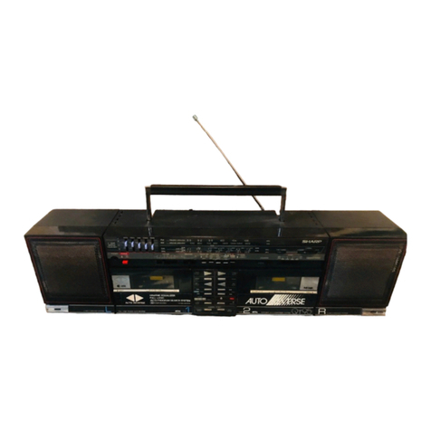
Sharp QT-MP5W User manual

QT-MP5W
– 1
CHAPTER 1. GENERAL DESCRIPTION
[1] Precaution For Using Lead-Free Solder........1-1
[2] Safety Precaution For Service Manual..........1-2
[3] Voltage Selection...........................................1-2
[4] AC Power Supply Cord and AC Plug Adaptor.. 1-2
[5] Specifications ................................................1-3
[6] Names Of Parts.............................................1-4
CHAPTER 2. ADJUSTMENTS
[1] Tuner Section................................................2-1
[2] Tape Deck Adjustments.................................2-2
CHAPTER 3. DIAGRAMS
[1] Block Diagrams.............................................3-1
CHAPTER 4. CIRCUIT DESCRIPTION
[1] Waveforms Of CD Servo Circuit....................4-1
[2] Voltage ..........................................................4-2
CHAPTER 5. CIRCUIT SCHEMATICS AND PARTS
LAYOUT
[1] Notes On Schematic Diagram.......................5-1
[2] Types Of Transistor And LED........................5-1
[3] Schematic Diagram .......................................5-2
[4] Wiring Side Of PWB ....................................5-12
CHAPTER 6. FLOWCHART
[1] Troubleshooting.............................................6-1
CHAPTER 7. OTHERS
[1] Function Table Of IC......................................7-1
[2] LCD Display.................................................7-11
PARTS GUIDE
SERVICE MANUAL
Parts marked with " " are important for maintaining the safety of the set. Be sure to replace these parts with specified ones
for maintaining the safety and performance of the set.
!
This document has been published to be used
for after sales service only.
The contents are subject to change without notice.
PORTABLE CD STEREO SYSTEM
QT-MP5W
MODEL
No. S0623QTMP5W//
In the Interests of user-safety the set should be restored to
its original condition and only parts identical to those
specified be used.
CONTENTS

QT-MP5W
1 – 1
A
udio
X
L-MP150
S
ervice Manual
X
LMP150
M
arket
E
[1] Precautions For Using Lead-Free Solder
1
.Employing lead-free solder
Example:
Indicates lead-free solder of tin,silver and copper.
2.Using lead-free wire solder
3.Soldering
When the tip of the soldering bit is blackened during use, file it with steel wool or fine sandpaper.
Be careful when replacing parts with polarity indication on the PWB silk.
Lead-free wire solder for servicing
Ref No. Description
Parts No.
PWB-A1
PWB-C
PWB-A2
PWB-A3
PWB-B
92LMP500280046
92LMP500380047
92LMP501280003
92LMP502300000
92LMP500980004
PWB-E 92LMP501380017
TAPE
AUDIO
TUNER
CONTROL
RECTIFIER
PWB-A4
SPEAKER
CD
The LF symbol indicates lead-free solder, and is attached on the PWB and service manuals.The alphabetical
character following LF shows the type of lead-free solder.
When fixing the PWB soldered with the lead-free solder, apply lead-free wire solder. Repairing with
conventional lead wire solder may cause damage or accident due to cracks.
As the melting point of lead-free solder (Sn-Ag-Cu) is higher than the lead wire solder by 40 C, were
commend you to use a dedicated soldring bit,if you are not familiar with how to obtain lead-free wire solder or
soldering bit,contact our service station or service branch in your area.
As the melting point of lead-free solder (Sn-Ag-Cu) is about 220 C which is higher than the conventional lead
solder by 40 C, and as it has poor solder wettability, you may be apt to keep the soldering bit in contact with the
PWB for extended period of time. However, since the land may be peeled off or the maximum heat-resistance
temperature of parts may be exceeded, remove the bit from the PWB as soon as you confirm the steady
soldering condition.
Lead-free solder contains more tin, and the end of the soldering bit may be easily corrected.Make sure to turn o
n
and off the power of the bit as required.
If a different type of solder stays on the tip of the soldering bit, it is alloyed with lead-free solder.Clean the bit afte
every use of it.
"AUDIO, CONTROL, RECTIFIER, SPEAKER, LED, CD, TUNER, TAPE, MCU PWB" of this model employs
lead-free solder.
PWB-A5
LED
PWB-F 92LMP502300000 MCU
CHAPTER 1.
GENERAL DESCRIPTION
QT-MP5W
1 – 2
[2] Safety Precaution For Service Manual
Precaution to be taken when replacing and servicing the Laser Pickup.
Laser Diode Properties
Material: AIGaAs
Wavelength: 790 nm
Emission Duration: continuous
Laser Output: max. 0.6 mW
[3] Voltage Selection
[4] AC Power Supply Cord and AC Plug Adaptor
92L15911022019

QT-MP5W
1 – 3
[5] Specifications
FOR A COMPLETE DESCRIPTION OF THE OPERATION OF THIS UNIT, PLEASE REFER
TO THE OPERATION MANUAL.
Aspartof ourpolicyofcontinuousimprovement, SHARPreservestherighttomakedesign and
specification changes for productimprovement without prior notice.The performance specificationfigures
indicated are nominal values of production units.There maybe some deviations from these values in
individual units.
General
Radio
Tape recorder
CD player
Power source AC 110 - 127/220 - 240 V, 50/60 Hz
DC12V [“D” size (UM/SUM-1, R20 or HP-2)
battery x 8]
Power
consumption Power on: 15 W
Output power MPO: 5.4 W (2.7 W + 2.7 W)
(AC OPERATION, 10% T.H.D)
RMS: 4 W (2 W + 2 W)
(DC OPERATION, 10% T.H.D)
Speaker type 2 way speaker system
10 cm (4") - 8 ohms x 2 - Speaker
4 cm (1 - 3/5") - 8 ohms x 2 - Tweeter
Dimensions Width: 410 mm (16-1/4")
Height: 165 mm (6-1/2")
Depth: 240 mm (9-1/2")
Weight 3.4 kg (7.5 lbs.) without battery
Frequency range FM: 88.0 - 108.0 MHz
AM: 531 - 1602 kHz
Frequency response 80 - 8000 Hz (Normal tape)
Signal/noise ratio 40 dB
Wow and flutter 0.3% (WRMS)
Motor DC 9 V electric governor
Bias system AC bias
Erase system Magnet erase
Type Compact disc player
Signal readout Non-contact,3-beamsemiconductorlaser
pickup
D/A converter 1-bit D/A converter
Frequency
response 60 - 20,000 Hz

QT-MP5W
1 – 4
[6] Names Of Parts
Front panel
1.Random Button
2.Memory/Display Button
3.On/Stand-by Button
4.Stand-by Indicator
5.CD Stop Button
6.Tape Button
7.Tuner (Band) Button
8.Equaliser Button
9.Extra Bass Button
10.CD Play/Pause Button
11.CD Repeat Button
12.Fast Reverse/Track Down/Tuner Preset Down Button
13.Tuner Tuning Down/Folder Down Button
14.Fast Forward/Track Up/Tuner Preset Up Button
15.Tuner Tuning Up/Folder Up Button
16.Volume Up and Down Button
Top panel
1.CD Compartment
2.Tape Record Button
3.Tape Play Button
4.Tape Rewind Button
5.Tape Fast Forward Button
6.Tape Stop/Eject Button
7.Tape Pause Button
8.Cassette Compartment
1324567
8
1234 56789
10 11 12 13 14 15 16
Back panel
1.Battery Compartment
2.Beat Cancel Selector
3.AC Input Socket
4.Headphone Socket
5.Reset Switch
6.FM/AM Aerial
7.Voltage selector
Display
1.Memory Indicator
2.Folder Indicator
3.Repeat mode Indicator
4.Random Indicator
5.Track Indicator
6.WMA Indicator
7.MP3 Indicator
8.CD Indicator
9.Disc Play/Pause Indicator
10.Equaliser modes Indicators
11.Tuner Stereo Indicator
MEMORY
TRACK
ROCK CLASSIC POPS JAZZ X BASS ST
WMA MP3
E
kHz
MHz
FOLDER 1PRANDOM
CD
TRACK
WMA MP3
CD
1
56789
243
10 11
3
14567
2

QT-MP5W
2 – 1
CHAPTER 2. ADJUSTMENTS
[1] Tuner Adjustments
Use a plastic screw driver for adjustments.
Adjust the intermediate frequency of AM to the frequency of ceramic filter.
Set of unit
Supply voltage : DC 12V
Speaker impedance : 8 ohms
Standard output : 50 mW
Function select : TUNER
Parts Location:
a. AM adjustment Band: AM
b. FM adjustment Band: FM FM Dummy antenna: 75 ohms unbalance
Step Adjusting
Circuit Connections SG
Frequency Position of
Tuning Dial Adjustment VTVM
Oscilloscope
Input Output
1IF
Close the output
terminal by sweep
generator, it place to
AM ANT
Connect VTVM to
C129(-) 450 KHz 520 KHz T103
2Tuning cover
range Connect AM SG to
test loop Connect VTVM to
R144 520 KHz 520 KHz T101 VT: 1.0+-/0.05V
1710 KHz 1710 KHz VT: 7.2+-/0.5V
3 Tracking Connect AM SG to
test loop Connect VTVM to
speaker terminals 600 KHz 600 KHz T102 Max.
1400 KHz 1400 KHz TC102
Step Adjusting
Circuit Connections SG
Frequency Position of
Tuning Dial Adjustment VTVM
Oscilloscope
Input Output
1IFConnect sweep
generator to C139 Connect VTVM to
C129(-) 10.7 MHz 90.00 MHz
2Tuning cover
range Connect FM SG to
D102(+) & D101(-) Connect VTVM to
R125 87.90 MHz 87.90 MHz L102 VT: 1.8+-/0.1V
107.90 MHz 107.90 MHz VT: 7.0+-/0.5V
3 Tracking Connect FM SG to
D102(+) & D101(-) Connect VTVM to
speaker terminals 90.00 MHz 90.00 MHz L101 Max.
106.00 MHz 106.00 MHz TC101
R144
L101 CT102
CT101 T102
T101
C129
L102
R125
T103

QT-MP5W
2 – 2
[2] Tape Deck Adjustments
1. HEAD REPLACEMNET
After replacement, demagnetize the heads by using a degausser.
Be sure to clean the heads before attempting to make any adjustments.
All wiring should be returned to the original position after work is completed.
2. HEAD AZIMUTH ADJUSTMENT
(1) Load the test tape (STT-113CN, etc., 8 KHz) for azimuth adjustment.
(2) Press the PLAY button.
(3) Use a cross-tip screwdriver to turn the screw for azimuth adjustment
so that left and right output are maximized.
(4) Press the STOP button.
(5) After completion of the adjustment, use thread lock (TB-1401B)
to secure azimuth-adjustment screw.
3. MOTOR REPLACEMENT
4. AC BIAS FREQUENCY ADJUSTMENTS
(1) Connect counter to T801 (BS).
(2) R/P switch in recording state.
(3) Adjusting T801 use a plastic screw, AC bias frequency: 80 KHz.
5. MOTOR SPEED ADJUSTMENT
(1) Insert the test tape (MTT-111N, etc., 3,000 Hz).
(2) Press the PLAY button.
(3) Use a flat-tip screwdriver to turn the SVR (located inside
the rear of the motor) to adjust SVR so that the frequency
counter become 3,000 Hz.
6. CHECKING THE MECHANISM TORQUSE AND TENSION
Measurement Take-up Torque Back Tension Tape Tension
Cassette of measurement PLAY: TW-2111A
F.FWD/REW: TW-2231 PLAY: TW-2111A Drive-power cassette
TW-2412
PLAY 30 - 70 gf.cm 1.5 - 5 gf.cm 70 gf or more
F.FWD 55 gf or more ------ ------
REW 55 gf or more ------ ------

QT-MP5W
3 – 1
CHAPTER 3. BLOCK DIAGRAM
A
B
C
D
E
F
G
H
123456
Figure 1: BLOCK DIAGRAM (1/2)

QT-MP5W
3 – 2
78 9 10 11 12
Figure 2: BLOCK DIAGRAM (2/2)

QT-MP5W
4 – 1
CHAPTER 4.
CIRCUIT DESCRIPTION
[1] Waveform Of Servo Circuit
121
272
347
IC901
IC901
IC901
422
518
IC901
IC901
422
623
724
IC901
IC901
IC901
825
IC901
422
623
724
IC901
IC901
IC901
825
IC901
422
623
724
IC901
IC901
IC901
825
IC901
422
623
724
IC901
IC901
IC901
825
IC901
92
IC901
Vp-p=1.0 V~1.3 V
0.5 mV/div,0.5 µsec/div

QT-MP5W
4 – 2
[2] Voltage
PIN PIN PIN PIN PIN PIN
NO NO NO NO NO NO
1 1.63 33 0.00 65 0.00 1 0.70 33 2.40 65 4.65
2 1.60 34 0.00 66 1.81 2 1.30 34 2.40 66 0.00
3 1.66 35 0.00 67 0.00 3 1.10 35 2.40 67 4.80
4 1.72 36 3.30 68 3.30 4 0.00 36 2.40 68 0.00
5 1.70 37 0.00 69 0.00 5 4.80 37 2.40 69 0.00
6 1.70 38 1.80 70 0.00 6 2.20 38 2.40 70 1.70
7 1.70 39 3.30 71 0.00 7 2.30 39 4.80 71 0.00
8 1.70 40 0.00 72 1.39 8 0.00 40 0.00 72 0.00
9 1.70 41 3.30 73 1.39 9 2.26 41 2.40 73 0.00
10 1.70 42 0.00 74 3.20 10 2.30 42 2.40 74 3.10
11 1.70 43 0.00 75 1.56 11 4.80 43 2.40 75 0.00
12 0.00 44 3.00 76 3.10 12 1.50 44 2.40 76 0.00
13 1.70 45 4.47 77 0.00 13 4.80 45 2.40 77 4.80
14 1.70 46 3.27 78 1.56 14 1.76 46 2.40 78 3.26
15 1.67 47 2.95 79 3.20 15 4.80 47 2.40 79 4.74
16 1.60 48 3.30 80 1.62 16 4.80 48 2.40 80 4.82
04.29408.47103.39406.171 04.20500.08100.00503.381 04.21508.49100.01500.091
20 0.00 52 0.00 PIN 20 1.96 52 2.40
21 3.30 53 0.00 NO 21 4.83 53 2.40
22 1.66 54 0.00 1 1.80 22 0.00 54 2.40
23 1.67 55 0.00 2 0.00 23 0.90 55 2.40
24 1.67 56 0.00 3 1.90 24 2.40 56 2.40
25 1.67 57 0.00 4 0.00 25 2.40 57 2.40
26 0.00 58 0.00 5 7.60 26 2.40 58 1.05
27 0.00 59 0.00 6 1.89 27 2.40 59 4.79
28 1.19 60 0.00 7 0.00 28 2.40 60 4.79
29 1.10 61 3.24 8 1.87 29 2.40 61 2.40
04.22604.20365
.12603.303 04.23604.21358.13600.013 04.24604.22398.14691.223
PIN PIN PIN PIN PIN
NO NO NO NO NO
1 7.92 15 3.31 1 12.25 1 0.65 16 0.00
2 0.00 16 3.93 2 6.10 2 0.15 17 3.17
3 1.66 17 1.66 3 11.30 3 0.00 18 3.17
4 1.66 18 1.66 4 1.21 4 0.00 19 3.16
5 3.63 19 3.63 5 0.00 5 3.10 20 3.17
6 3.63 20 3.63 6 12.00 6 3.10 21 3.10
7 0.00 21 0.00 7 0.00 7 3.17 22 3.16
8 0.00 22 0.00 8 0.00 8 3.17 23 3.17
9 3.63 23 3.63 9 1.21 9 3.17 24 3.17
10 3.63 24 3.63 10 11.30 10 3.10 25 3.10
11 1.67 25 1.67 11 6.30 11 3.17 26 3.10
12 1.66 26 1.67 12 13.00 12 3.17 27 0.00
01.38271.33106.17203.331 63.6927
1.34129.78232.741 15 0.00 30 0.63
IC902
BA3308
VOLTAGE
LA6548
VOLTAGE VOLTAGE
LA4227
VOLTAGE
LC75342M
VOLTAGE
VOLTAGE
IC201
VOLTAGE
105CI103CI
IC701
LC87F7CC8A
EGATLOVEGATLOV VOLTAGE
IC901
LC78690W
VOLTAGE VOLTAGE

QT-MP5W
5 – 1
CHAPTER 5. CIRCUIT SCHEMATICS AND PARTS LAYOUT
[1] Notes On Schematic Diagram
•Resistor:
To differentiate the units of resistors, such symbol as
K and M are used: the symbol K means 1000 ohm
and the symbol M means 1000 kohm and the
resistor without any symbol is ohm-type resistor.
Besides, the one with “Fusible” is a fuse type.
• Capacitor:
To indicate the unit of capacitor, a symbol P is used:
this symbol P means pico-farad and the unit of the
capacitor without such a symbol is microfarad. As to
electrolytic capacitor, the expression “capacitance/
withstand voltage” is used.
(CH), (TH), (RH), (UJ): Temperature compensation
(ML): Mylar type
(P.P.): Polypropylene type
• Schematic diagram and Wiring Side of P.W.Board
for this model are subject to change for
improvement without prior notice.
• The indicated voltage in each section is the one
measured by Digital Multimeter between such a
section and the chassis with no signal given.
1. In the tuner section,
indicates AM
indicates FM stereo
2. In the audio section, a tape is being played back.
3. In the deck section, a tape is being played back.
( ) indicates the record state.
4. In the rectifier section, a tape is being played
back.
5. In the CD section, the CD is stopped.
• Parts marked with “ “ ( ) are
important for maintaining the safety of the set. Be
sure to replace these parts with specified ones for
maintaining the safety and performance of the set.
[2] Types Of Transistor And LED
REF. NO DESCRIPTION POSITION
SW710 Stop ON—OFF
SW711 Repeat / Random ON—OFF
SW712 Fast Forward / Track Up /
Tuner Preset Up ON—OFF
SW713 Tuner Tuning Down / Folder Down ON—OFF
SW714 Tuner Tuning Up / Folder Up ON—OFF
SW715 Volume Down ON—OFF
SW716 Memory Display ON—OFF
REF. NO DESCRIPTION POSITION
SW701 Power On / Stand-by ON—OFF
SW702 Fast Reverse / Track Down /
Tuner Preset Down ON—OFF
SW703 Equaliser ON—OFF
SW704 Extra Bass ON—OFF
SW705 USB Play / Pause ON—OFF
SW706 CD Play / Pause ON—OFF
SW707 Tuner (Band) ON—OFF
SW708 Tape ON—OFF
SW709 Volume Up ON—OFF
HY3C
HY4C
B
(3)
E
(1)
C
(2)
TOP
VIEW
TOP VIEW
A928A
9014C
S8550
S8050
9015C
CW7809
B1185
B772
VIEW
FRONT
VIEW
FRONT
E C B
E C B
(S)(G)(D)
(1)(2)(3) 1N4001
1N4148
FRONT
VIEW
92L22708030000
92L22708050012

QT-MP5W
5 – 2
[3] Schematic Diagram
Figure 5-1: AUDIO SCHEMATIC DIAGRAM (1/3)

QT-MP5W
5 – 3
Figure 5-2: AUDIO SCHEMATIC DIAGRAM (2/3)
LED PWB-A4
AUDIO PW
B

QT-MP5W
5 – 4
Figure 5-3: AUDIO SCHEMATIC DIAGRAM (3/3)
D
IO PWB-A1
SPEAKER
PWB-E
13 14 15 16 17 18

QT-MP5W
5 – 5
A
B
C
D
E
F
G
H
123456
Figure 5-4: CONTROL SCHEMATIC DIAGRAM

QT-MP5W
5 – 6
PT1
AC SOCKET
(VS1)
AC SUPPLY
110-127 / 220-240V
50 / 60Hz
A
B
C
D
E
F
G
H
123456
Figure 5-5: RECTIFIER SCHEMATIC DIAGRAM

QT-MP5W
5 – 7
-MEMO-

QT-MP5W
5 – 8
CN902
TO DA11MMV
IC901
LC78690W
SW901
Limit Switch
A
B
C
D
E
F
G
H
123456
Figure 5-6: CD SCHEMATIC DIAGRAM (1/2)

QT-MP5W
5 – 9
CN903
TO MAIN PWB CN903A
CN901
TO MAIN PWB CN901A
78 9 10 11 12
Figure 5-7: CD SCHEMATIC DIAGRAM (1/2)
Other manuals for QT-MP5W
1
Table of contents
Other Sharp Stereo System manuals

Sharp
Sharp CD-G20000 User manual

Sharp
Sharp CD-XP200W User manual

Sharp
Sharp MD-X5H User manual

Sharp
Sharp CD-BA1200H User manual

Sharp
Sharp CD-C410H User manual

Sharp
Sharp XL-1100H User manual

Sharp
Sharp XL-S15H User manual

Sharp
Sharp XL-MP40H User manual

Sharp
Sharp CD-SW340 User manual

Sharp
Sharp XL-S10H User manual

Sharp
Sharp QT-95H User manual

Sharp
Sharp XL-55W User manual

Sharp
Sharp QT-V5E User manual

Sharp
Sharp XL-B515D User manual

Sharp
Sharp CD-MPS900 User manual

Sharp
Sharp CD-RW5000 User manual

Sharp
Sharp XL-B510(BK) User manual

Sharp
Sharp QT-CD180H User manual

Sharp
Sharp XL-DAB151PH(S) User manual

Sharp
Sharp CD-MPS777H User manual