Sharp GF-9090H User manual

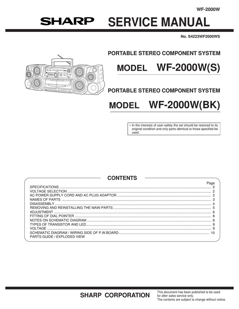
GF-9090H.HB
GF-9090E
Manual
@
APSS
Auto
Program
Search
System
MODEL
GF-9O09OH
sinver
Panes
GF-9O90B#B
eeiack
Pane!
GF-9090E
In
the
interests
of
user-safety
the
set
should
be
restored
to
its
original
condition
and
only
parts
identical
to
those
specified
be
used.
SPECIFICATIONS
GENERAL
Type:
Power
source:
Power
consumption:
Speaker:
Power
output:
Semiconductors:
Dimensions:
Weight:
Input
terminals:
Output
terminals:
Portable
stereophonic
cassette
tape
re-
corder
with
built-in
LW/MW/SW/FM
4-band
radio
AC
110/220/240V,
50/60
Hz(H,
HB)
AC
240V,
50/60
Hz
(E)
DC
12V
(Eight
UM/SUM-1
batteries
or
External
DC
supply)
24
watts
16cm
(Woofer)
x
2,
Horn
type
(Twee-
ter)
x
2
MPO
8000
mW
(DIN
45
324)
(H,
HB)
MPO
11W
(E):
AC
operation
RMS
power
7000
mW
(3500
mW
+
3500
mW:
DC
operation)
5-IC
(Integrated
Circuit),
47-transistor
and
37-diode
(4
Light
Emitting
Diode)
485mm(W)
x
115mm(D)
x
240mm(H)
5.8
kg
(without
batteries)
EXT.
MIC.
600
ohms
(J201,
J202)
Remote
control
(J302)
EXT.
DC
power,
12V
(J701)
AC
input
power
(SO701)
REC/PB
DIN
socket,
2.5
mV/10K
ohms
(SO202)
FM
EXT.
Antenna
(SO1)
EXT.
speaker,
4
~
8-ohms
(SO301,
$0302)
PHONES
:
4
~~
8
ohms
(J301)
REC/PB
DIN
-
socket,
1V/50K
ohms
(SO202)
=O
MAPWNH
WN
TAPE
RECORDER
SECTION
Type:
Tape:
Tape
speed:
Recording
system:
Erasing
system:
Recording
time:
Fast
forward
or
rewind
time:
Frequency
response:
Wow
and
flutter:
S/N
ratio:
RADIO
SECTION
Frequency
range:
Intermediate
frequency:
Circuit
system:
Antenna:
4-track
stereo
cassette
tape
recorder
Philips
type
compact
cassette
tape
4.8
cm/sec.
AC
bias
DC
erasing
60
minutes
(with
C-60
tape)
120
sec.
(with
C-60
tape)
40
~
15,000
Hz
(CrO2
tape)
40
~
12,000
Hz
(Normal
tape)
0.3%
(DIN
45
511)
(H,
HB)
0.15%
(WRMS)
(E)
dB
50
LW
150
~
285
kHz
MW
520
~
1,620
kHz
SW
5.95
~
18
MHz
FM
87.6
~
108
MHz
LW/MW/SW
455
kHz
FM
10.7
MHz
4-band
superheterodyne
system
LW/MW
ferrite
core
bar
antenna
SW/FM
telescopic
antenna
FM
EXT.
antenna
SHARP
CORPORATION
OSAKA,
JAPAN

NAMES
OF
PARTS
(Refer
to
Figure
1)
Record
key
Rewind/Review
key
Playback
key
Eject
key
Fast
forward/Cue
key
ae
ae
st
——
Function
selector
switch
Editor
switch
FM
muting
switch
Pause
key
—__----—~
AFC
switch
FM/SW
rod
antenna
Band
selector
switch
Meter
ial/Mete:
:
Dial/Meter
selector
switch
light
switch
Record
level
control
(L-ch}
(R-ch}
Loudness
switch
Stop
key
Bass
control
ALC/Manual
switch
Treble
control
Forward
Reverse
——_————
Equalizer
selector
switch
APSS
key
APSS
key
Balance
control
Bias
selector
switch
Volume
control
——..———-.
a
Mode
selector
switch
Tuning/R-ch
record
_
a
:
a
=
FM
stereo
indicator
and
playback
level
meter
Z|
Battery
condition/L-ch
record
and
playback
tevel
meter
~
|
r 7
-
--——
APSS
indicator
—
Tuning
control
Built-in
i
Built-in
microphone
preeenste
i
(R-ch)
PULL
ARO
STOP
Digital
tape
counter
Headphone
jack
|
a
-——
Cassette
holder
Remote
control
jack
External
microphone
jack
Mains
RIF
socket
Record/Play
back
switch
socket
(DIN)
External
x
DC
jack
Battery
compartment
lid
I
_____
Mains
voltage
selector
switch
(GF-9090H,HB)
Mains
Power
switch
(GF-9090E)
FM
external
antenna
socket
—
—
|
aan
External
speaker
socket
(R-ch)
(L-ch}
Figure
1

DISASSEMBLY
OPERATION
ON
MAINS
A->|BE={C
{DFE
|
GF-9090H,
HB
™
Before
operating
the
unit
on
mains,
check
the
pre-set
[A]
FRONT
CABINET
REMOVAL
(Refer
to
Figures
2
and
3)
1.
Pull
out
the
power
cord
plug
or
adaptor
plug
from
the
unit.
2.
Take
out
the
cassette
tape
from
the
cassette
holder.
3.
Remove
the
battery
compartment
lid
and
eight
(8)
bat-
teries
from
the
battery
compartment.
.
Remove
eight
(8)
screws
retaining
the
front
cabinet.
5.
Gently
pull
out
the
front
cabinet
and
disconnect
four
(4)
tips
(Speaker)
connected
to
the
main
P.W.
board.
-
voltage.
If
the
voltage
is
different
from
your
local
voltage,
adjust
the
voltage
as
follows:
Rotate
the
plug
of
the
voltage
selector
by
using
a
screwdriver
so
that
your
local
voltage
number
can
be
seen.
(Refer
to
Figure
6)
GF-9090E
Switch
the
mains
power
switch
to
the
“ON”
position.
®
When
the
unit
is
used
on
batteries,
pull
out
the
mains
B|
OPERATION
PANEL
REMOVAL
(Refer
to
Figure
2)
plug
from
the
unit.
Otherwise
switch
off
at
the
mains
SWITGh
1.
Remove
the
front
cabinet
as
described
in
front
cabinet
power
switch
after
use.
(Refer
to
Figure
6)
GF-
9090E
removal.
Figure
2
Figure
6
2.
Remove
six
(6)
knobs
(VOLUME,
BALANCE,
TREBLE,
DIAL
CORD
STRINGING
(Refer
to
Figure
7)
BASS
and
RECORD).
|
.
Remove
four
(4)
screws
retaining
the
operation
panel.
4.
Gently
lift
up
the
operation
panel
from
the
back
cabinet.
Ww
[(C]
DIAL
SCALE PLATE
REMOVAL
(Refer
to
Figure
3)
1.
Remove
the
operation
panel
as
described
in
operation
panel
removal.
2.
Remove
four
(4)
screws
retaining
the
dial
scale
plate.
3.
Gently
pull
out
the
dial
scale
plate
from
the
chassis.
DIAL
POINTER
PULLEY
[D]
MECHANISM
BLOCK
REMOVAL
(Refer
to
Figure
4)
1.
Remove
the
dial
scale
plate
as
described
in
dial
scale
plate
removal.
2.
Disconnect
the
tip
(Muting)
and
two
(2)
sockets
(SO2,
$0501)
connected
to
the
main
P.W.
board
and
the
motor
P.W.
board.
3.
Remove
four
(4)
screws
retaining
the
mechanism
block.
4.
Gently
pull
out
the
mechanism
block
form
the
back
cabinet.
PULLEY
[E]
CHASSIS
(P.W.B.)
REMOVAL
(Refer
to
Figure
5)
1.
Remove
the
mechanism
block
as
described
in
mechanism
block
removal.
2.
Remove
the
tuning
knob from
the
tuning
shaft.
3.
Disconnect
two
(2)
tips
(Antenna)
connected
to
the
main
TUNING
SHAFT
P.W.
board.
4.
Remove
six
(6)
screws
retaining
the
chassis
(P.W.B.).
5.
Gently
pull
out
the
chassis
(P.W.B.)
from
the
back
cabinet.
enWs
Li)
OY)
Ay
_———/
Zo
ae
=
a
Figure
5
Figure
7

DESCRIPTION
OF
APSS
APSS
is
the
abbreviation
of
Automatic
Program
Search
System
that
permits
advancing
the
tape
past
an
unwanted
selection
to
the
beginning
of
the
next
program
automati-
cally
with
one
push
of
a
key.
In
this
machine,
the
APSS
in
the
reverse
direction
is
also
realized
besides
that
in
the
forward
play.
That
is
to
say,
this
unit
is
equipped
FWD.-
APSS
key
(
<q
)
and
REV.-APSS
key
(
p>
).
In
playback
mode
when
the
FWD.-APSS
key
is
depressed
the
tape
is
fed
at
a
high
speed
and
is
slowed
down
to
a
regular
play
speed
at
the
beginning
of
the
next
selection.
Or,
when
the
REV.-APSS
key
is
depressed
the
tape
is
rewound
at
a
high
speed
and
is
set
to
regular
playback
mode
at
the
beginning
of
the
selected
program.
The
following
explana-
tion
refers
to
the
function
of
the
APSS.
FUNCTION
OF
APSS
When
the
FWD.-APSS
key
is
depressed
in
playback
mode
of
the
tape,
the
pinch
roller
is
cleared
from
the
flywheel
shaft
and
the
roller
assembly
meshes
with
the
gear
of
the
take-up
turntable
permitting
the
tape
to
advance
at
a
normal
fast
forward
speed.
On
the
other
hand,
when
the
@)
APSS
INDICATOR
CIRCUIT
(Refer
to
Figures
8,
9,
10
and
11)
With
the
APSS
indicator
circuit
being
given
+12V
power,
the
multi-vibrator
(Q502
and
Q501)
starts
to
oscillate
to
n
Hz
(about
2
Hz)
and
output
of
the
multi-vibrator
will
be
applied
to
the
flip-flop
circuit
(Q503
and
Q504)
to
be
1/2
divided
into
1/2n
Hz
(about
1
Hz).
These
outputs
of
the
multi-vibrator
and
flip-flop
circuit
are
to
light
up
the
light
emitting
diodes
DS13,
D512
and
D511
through
the
logical
circuit
(D501
to
D506).
Figure
10
is
a
timing
chart
concerning
the
above
operation.
In
Figure
10,
1)
and
2)
are
output
waveformes
of
the
multi-vibrator
(Q502
and
Q501),
and
3)
and
4)
are
those
of
the
flip-flop
circuit
(Q503
and
Q504).
Using
these
four
(4)
waveforms,
the
logical
circuit
is
to
further
create
waveforms
5),
6)
and
7)
to
have
the
light
emitting
diodes
light
up.
The
horizontal
axis
shown
in
Figure
10
refers
to
a
time
axis:
the
light
emitting
diodes
D513,
D512
and
D511
light
up
in
this
order
one
after
another,
respectively
at
the
periods
a,
b
and
c.
Meanwhile,
at
the
period
d,
all
the
light
emitting
diodes
are
kept
off.
The
periods
a
to
d
are
considered
one
cycle
of
the
light-up
operation
and
this
cycle
is
repeated:
the
light-up
operation
looks
as
if
it
moved
from
right
to
left.
Q505
and
Q506
are
switching
transistors.
When
the
FWD.-APSS
key
is
depressed,
the
Q505
will
be
turned
“ON”
while
the
Q506
will
do
so
when
the
REV.-APSS
key
is
depressed.
As
for
the
REV.-APSS
operation
mode,
the
light
emitting
diodes
D511,
D512
and
D513
light
up
in
this
order
one
after
another,
respectively
at
the
periods
a,
b
and
c
---
the
light-up
operation
looks
as
if
it
moved
from
left
to
right.
FWD.-APSS
key
is
depressed,
the
FWD.-APSS
switch
(SWSO1)
is
turned
“ON”
so
that
+12V
power
be
applied,
via
D509,
to
the
APSS
indicator
circuit
1)
,
muting
circuit
(2)
and
APSS
detection
circuit
@.
Playback
key
Record
key
Fast
forward
Rewind/
/Cue
key
mm.
Review
key
Pause
key
Eject
key
Forward
Reverse
APSS
key
APSS
key
(FWD-APSS)
(REV-APSS}
Stop
key
Figure
8
FUNCTION
KEY
LAYOUT
Q501~9506
ascassic)
ALY
APSS
INOKATOR,
Figure9
APSS
INDICATOR
CIRCUIT
APSS
INDICATOR
PERIOD
jee
NUE
PLLA
[
a
|
r
1
3)
$03
COLLECTOR
|
4).
0604
COLLECTOR
2)
@502
COLLECTOR
[]
I,
Sl
ie
oe
[ee
a
ce
ie
T
Telolelalelelelalalvlel
Tale
le {time
0511,0512
and
D513
OFF
Period
O5I1
ON
Period
OSI2
ON
Period
‘$13.
ON
Period
5)
D511
ANODE
Zam
pee
te
t
6)
0512
ANODE
7)
DS5t3
|
ANODE
ota
|
1
OOHOHORY
LEFT
RIGHT
Figure
10
FWD-APSS
IND.
TIMING
CHART
(2)
MUTING
CIRCUIT
(Refer
to
Figure
12)
The
current
fed
to
the
muting
circuit
turns
“ON”
the
muting
transistor
(Q302
and
Q305)
and
attenuates
the
signal
from
head
to
hold
back
the
monitor
noise.
APSS
DETECTION
CIRCUIT
(Refer
to
Figures
13,
14
and
15)
The
current
fed
to
the
APSS
detection
circuit
drives
the
tape
playback
signal
given
from
the
record/playback
head
into
the
APSS
pre-amp
(IC401)
through
the
equalizer
amp
(Q201
to
Q204)
and
APSS
mixer
(Q205),
turning
“ON”
the
Q401,
and
now
the
signal
is
amplified
to
exceed
VBE
(voltage
between
base
and
emitter)
and
charges
the
C406
up
to
+12
volts.
Next,
when
the
Q402
is
turned
“ON”,
the
Q403
is
turned
“OFF”,
and
the
potential
of
the
Q403
collector
stabi-
lizes
at
+12
volts.
Therefore
the
Q404
is
not
turned
“ON”,
in
consequence,
neither
is
the
Q405.
As
a
result,
the
plunger
is
not
actuated.
In
other
words,
as
far
as
the
tape
carries
signals
the
plunger
does
not
work,
that
is,
the
tape
is
continuously
fast
forwarded
according
to
the
mechanism
of
the
APSS.
Meanwhile,
when
there
is
no
signal
on
the
tape,
the
potential,
even
if
amplified
by
the
equalizer
amp
(Q201
to
Q204)
and
APSS
pre-amp
(IC401),
becomes
lower
than
VBE
of
Q401,
which,
therefore,
is
turned
“OFF”,
and
the
electric
charge
of
C406
(determined
by
the
value
of
R405
and
C406)
is
discharged
at
the
time
constant.
When
the
potential
of
C406
is
discharged
to
be
below
VBE
of
Q402,
the
Q402
is
turned
“OFF”
and
the
Q403
is
activated.
Therefore,
the
collector
potential
of
Q403
becomes
zero
(0)
volt
and,
consequently,
the
+12-
volt
voltage
passes
through
the
R412,
allowing
a
discharge
current
to
flow
towards
the
C407.
By
this
discharge
current
the
potential
of
the
Q404
base
drops
momentarily
to
zero
(0)
volt,
and
the
Q404
is
turned
“ON”.
tees
REV-APSS
APSS
INDICATOR
PERIOD
an
h
+)
Q501
COLLECTOR
|
MULTI-VIBRATOR]
rer
2)
0502
COLLECTOR
LI
LU
[|
padi
oe
ty
=
3)
9803
COLLECTOR
LL
—j
LN
FLIP-FLOP.
m
r
4)
Q504
COLLECTOR
_
To
5)
DSi!
ANODE
]
[|
sa
6)
D512
ANODE
|
[
]
—4$
7)
DSI3
ANODE
[|
‘|
i
F
4h;
[
Tololelalalefelatalele!
lalele|
time
--4a-,
|
|
DSI1,DSI2
ond
DSIS
OFF
Period
Gb)
REV)
D513
ON
Period
LEFT
RIGHT
DSI2
ON
Period
DSII
ON
Period
Figure
11
REV-APSS
IND.
TIMING
CHART
Q301,Q304
2S8C373
DIN
AMP
Q302,Q305
2SC372(Y)
MUTING
Roch
C302
R308
10/16V
wK
BUFFER
PRE.
AMP.
ae
AMP.
APSS
DET.
CIRCUIT
GROUND
°
V
V
V
R/P
SWITCH
(SW2OI-K,1)
Figure
12
MUTING
CIRCUIT
{L602)
Q201,Q203
2SCIG82IGR)
EQ
AMR:
Ra);
0202,0204
te,
>
gurren
RECORD/PLAY
BACK
Seat
HEAD
c204
APSS
DET.
CIRCUIT
28C373
MIXER
{>
BUFFER
AMP.
DOIN
SOCKET
(so202)
{L603}
Ae
Figure
13
EQ
AMP.

Accordingly,
the
potential
of
the
C407
is
permitted
to
be
stabilized
from
zero
(0)
volt
to
+12
volts.
When
the
potential
exceeds
VBE,
the
Q404
is
turned
“OFF”.
Then
the
Q404
is
turned
“ON”’,
and
+B
is
supplied
to
the
base
of
Q405
through
the
R414,
turning
“ON”
the
Q405.
Then,
an
end
of
the
plunger
is
grounded
and
+12V
is
applied
to
the
plunger,
which,
in
turn,
is
actuated.
When
the
Q404
is
turned
“OFF”,
the
Q405
is
also
turned
“OFF”’,
cutting
off
the
potential
to
the
plunger.
When
the
plunger
is
put
in
action,
the
APSS
lockplate
is
stretched
out
to
release
the
FWD-APSS
key.
Consequently,
the
FWD-APSS
switch
(SW501)
is
turned
“OFF”
and
the
pinch
roller
is
pressed
hard
against
the
flywheel
shaft.
Moreover,
the
fastforwarding
gear
is
disengaged
from
the
gear
of
the
takeup
turntable,
setting
the
unit
in
normal
playback
mode
again.
As
the
FWD-APSS
switch
(SW501)
is
turned
“OFF”,
the
light
emitting
diodes
of
D513,
D512
and
D511
stops
flickering
and
the
APSS
limiter
circuit
is
made
inactive.
Further,
the
muting
circuit
of
Q302
and
Q305
also
stops
its
function.
In
the
meantime,
when
the
REV-APSS
key
is
depressed
the
fast-forwarding
gear
meshes
with
the
gear
of
supply
turntable
and
the
REV-APSS
switch
(SW502)
is
turned
“ON”
to
set
the
tape
in
rewind
mode,
permitting
the
light
emitting
diodes
of
D511,
D512
and
D513
to
flicker.
The
successive
function
is
just
as
in
the
case
of
FWD-APSS
behavior.
This
ends
the
explanation
of
the
APSS
performance.
However,
that
the
APSS
may
malfunction
when
either
one
of
following
recordings
is
played
back,
but,
remember,
this
is
not
a
trouble.
1.
2:
a
A
prolonged
portion
of
pianissimo
in
music.
A
blank
portion
in
the
midst
of
music
(more
than
3
seconds
when
measured
in
playback).
*
In
cases
1
&
2
the
FWD-APSS
or
REV-APSS
key,
if
depressed,
resets
itself
and
regular
playback
mode
is
resumed.
.
A
too
short
interval
between
programs
(about
1
second
when
measured
in
playback).
.
Anoisy
hum
or
buzz
recorded
in
a
blank
portion.
*
In
cases
3
&
4
the
condition
doesn’t
allow
the
APSS
circuit
to
work
easily,
and
the
blank
portion
couldn’t
be
detected.
.
FWD-APSS
key
depressed
within
10
seconds
(as
measured
in
playback)
from
the
end
of
a
preceding
selection.
.
REV-APSS
key
depressed
within
10
seconds
(as
meas-
ured
in
playback)
from
the
beginning
of
a
selection.
*
In
cases
5
&
6
the
tape
runs
10
or
30
times
as
fast
as
in
playback
mode
if
the
FWD-APSS
or
REV-APSS
key
is
depressed,
therefore
the
tape
skips
a
blank
portion
while
the
key
is
being
depressed.
APSS
MIXER
MUTING
CIRCUIT
[—————~1
APSS
IND.
CIRCUIT
I+12V
f——>
PLUNGER
({SOLSOI)
R401
sepa
15K
c4or
022(Z)
\C
-40]
RH-IXO408AFZZ
Po
R40:
age
|
ex
|
Binh
2
47K
ve
©.
+
C406
04
3.3/50V(M
OMP
A
02
)
©
GROUND
Q401
2SA495(Y)
Q402,Q403
2SC372Y(Y)
Q404
2SA495(Y)
SWITCHING
Q405
2SD468(C)
PLUNGER
DRIV.
Figure
14
APSS
DETECTION
CIRCUIT
[mee
APSS
SW
sw501
|FwD.
APSS
Sw
(REV
aPSS
SW)
ON
(Sw502)|
(REV.
APSS_
SW)
OFF.
Voss
a
_
BLANK
<.
MUSIC
A
SECTION
MUSK
B
H
EQUALIZER
AMP.
(Q201-
0204)
|
]
APSS
MIXER(Q208)
| \
|
'
!
!
| |
APSS
PRE
AMP
(IC
401)
=e
|
TIME
CONSTANT
|
pT
(R408
,c406)
TERMINAL
os
|
VeE
VOLTAGE
|
|
we
:
nee
9401
=
(282L
econ}
1
Ve
|
|
|
rt
i
(
9402
)
I
COLLECTOR
|
ON
|
ne
|
|
Sees
OFF
|
(2403
)
:
COLLECTOR
|
=
fete
SS
fe
(sate
Laon)
i
i
!
it
1
=a
!
if
0403
(Vee)
! i
|
|
\
404(0N)}
|
!
OFF
T
tot
i
I
!
t
]
|
OFF
i
'
I
!
¥
i
TAPE
Hi
1
!
NORMAL
SPEED
SPEED
|
|
x
10~
30
are
:
I
Refer
to
Figures
10,1!
(
0404
)
COLL
ECTOR
PLUNGER
KE
APSS
IND.
LAMP
(LEO)
Figure
715
APSS
MOVEMENT
PRINCIPLE

MECHANICAL
ADJUSTMENT
=
PLAY
ADJUSTMENT
OF
FLYWHEEL
SHAFT
THRUST
+.
(Refer
to
Figure
16)
1.
Slowly
rotate
the
flywheel
shaft
thrust
play
adjusting
screw
clockwise
until
there
will
be
no
thrust
play.
2.
Next,
rotate
the
thrust
play
adjusting
screw
about
1/4
of
its
full
turn
counter
clokwise.
(Since
1
pitch
of
the
adjusting
screw
refers
to
0.8
mm,
the
thrust
play
thus
created
becomes
0.1
mm
to
0.3
mm.)
ADJUSTMENT
SCREW
Ol
mm
0.3mm
FLYWHEEL
Figure
16
@
PINCH
ROLLER
PRESSURE
ADJUSTMENT
(Refer
to
Figure
17)
1.
Set
the
unit
in
PLAY
mode.
2.
Push
the
point
@
with
use
of
tension
gauge
(0
gr.
to
500
gr.)
to
make
the
pinch
roller
apart
from
the
fly-
wheel
shaft.
Then,
check
that
the
tension
gauge
will
read
300
gr.
to
400
gr.
when
the
pinch
roller
stops
to
rotate.
.
As
a
result
of
the
check
in
the
step
2
above,
if
the
reading
is
found
outside
the
range
of
300
gr.
to
400
gr.,
adjust
the
pressure
spring
of
pinch
roller
by
bending
it
or
replace.
WwW
PRESSURE
SPRING
Figure
17
@
OPERATION
CHECK
OF
FWD-APSS
AND
REV-APSS
MECHANISMS
(Refer
to
Figures
42
and
43,
Page
29
and
30)
Under
PLAY
mode,
slowly
push
the
FWD-APSS
key
or
REV-APSS
key
to
make
sure
that
the
pinch
roller
(090)
and
the
take-up
idler
(028)
come
off
respectively
from
the
flywheel
shaft
and
the
take-up
turntable
support
(081),
and
simultaneously
the
sub-chassis
(011)
moves
1
mm
to
1.5
mm,
and
further
that
thereafter,
the
roller
assembly
(089)
is
pressed
against
the
take-up
turntable
support
(081)
or
the
supply
turntable
support
(082).
Moreover,
when
the
FWD-APSS
key
or
REV-APSS
key
is
released
by
pushing
the
FF
(CUE)
key
or
the
REWIND
(REVIEW)
key,
make
ascertain
that
the
sub-chassis
(011)
is
reset
and
the
unit
gets
in
PLAY
mode.

=
TORQUE
MEASUREMENT
AT
PLAY,
FF
AND
REWIND
MODES
(Refer
to
Figure
18)
1.
Mount
a
torque
measuring
reel
on
the
reel
support
(that
is,
it is
placed
on
the
take-up
turntable
support
at
PLAY/
REWIND
mode
while
on
the
supply
turntable
support
at
REWIND
mode).
2.
Then
gradually
release
the
tension
gauge
and
read
it
when
the
rotational
speed
of
the
reel
support
becomes
almost
constant.
3.
Measured
torques
at
each
mode
should
be
as
tabulated
below.
Note:When
the
take-up
turntable
support
is
stopped
at
PLAY
mode,
there
should
be
no
slip
between
the
take-up
turntable
support
and
take-up
slip
roller
and/or
between
the
drive
belt
and
take-up
slip
roller.
TURN
TABLE
MEASURING
—__20(25/32")
REEL
TENSION
GAUGE
MEASURED
TORQUE
35~
60
gr.cm
70
~
100
gr.cm
70
~
100
gr.cm
REWIND
Figure
18
=
GAP
ADJUSTMENT
BETWEEN
MOTOR
SWITCH
AND
BRAKE
LEVER
(Refer
to
Figure
19)
1.
Under
each
of
PLAY,
FF,
and
REWIND
modes,
make
ascertain
that
the
motor
switch
(SW504)
is
turned
“ON”
without
fail.
2.
When
the
motor
is
in
a
stop,
check
that
the
gap
(A)
between
the
brake
lever
and
the
motor
switch
(SW504)
is
2
mm
to
3
mm.
3.
If
the
steps
1
and
2
above
are
still
insufficient
for
the
adjustment,
the
gap
can
be
adjusted
by
positionally
changing
the
two
soldered
terminals
of
motor
switch
(SW504)
located
at
the
motor
PWB
with
use
of
a
soldering
iron.
MOTOR
SWITCH
(SW504)
__
BRAKE
LEVER
OPERATION
CHECK
OF
PAUSE
MECHANISM
(Refer
to
Figure
42,
Page
29)
Set
the
unit
in
PLAY
mode
by
pushing
the
key
given
a
mark
(
<q
).
Then
slowly
push
the
PAUSE
key
and
make
ascertain
that
the
take-up
idler
(028)
and
the
pinch
roller
(090)
come
off
respectively
from
the
take-up
turntable
support
(081)
and
the
flywheel
shaft
almost
at
the
same
time
and
check
that
each
of
the
two
gaps
thus
produced
is
about
0.5
mm.
TURNTABLE
Figure
19
@
ADJUSTMENT
OF
PLUNGER
SETTING
POSITION
(Refer
to
Figure
20)
1.
Under
FF
mode,
loosen
the
plunger
retaining
screw,
hold
up
the
part
@)
of
the
plunger
by
hand
and
while
keeping
the
plunger
in
contact
with
the
lock
shaft,
retighten
the
plunger
retaining
screw.
2.
After
the
step
1,
make
sure
of
the
following.
«Check
that
each
of
the
PLAY,
FF
(CUE),
REWIND
(REVIEW)
keys
can
be
locked
smoothly.
-
Check
that
the
FWD-APSS
key
and
REV-APSS
key
can
be
locked
smoothly
and
they
further
be
released
when
the
plunger
operates.
-
Check
that
the
plunger
can
start
to
operate
smoothly
when
the
STOP
key
is
pushed
to
release
the
APSS
keys.
3.
After
the
step
2,
the
adjustments
are
not
yet
sufficient,
again
carry
out
the
step
1.
PLUNGER
ADJUST
SCREW
LOCK
SHAFT
PLUNGER
_
Figure
20
10

ELECTRICAL
MEASUREMENT
*
This
unit
operaters
on
DC
12
V.
Check
that
the
power
*
Refer
to
Figure
35.
supply
is
exactly
12
V
before
measurement.
*
Set
the
FUNCTION
switch
(SW101G)
to
“TAPE”
position.
m
RECORD
OSCILLATOR
BIAS
CURRENT
AND
BIAS
FREQUENCY
ADJUSTMENT
(Refer
to
Figure
21)
1.
Connect
the
V.T.V.M.
across
the
100
ohm
resistor
5.
As
a
result
of
the
check
in
the
step
5
above,
if
the
(R201,
R202).
reading
is
found
outside
the
53
+
1
kHz,
adjust
the
2.
Place
the
unit
in
RECORD
mode.
bias
oscillation
coil
(L601)
3.
Adjust
the
semi-variable
resistores
(VR601,
VR602)
6.
After
the
step
5,
again
make
sure
of
the
bias
current.
so
that
the
V.T.V.M.
reads
50
mV
for
the
right
channel
(R201)
and
left
channel
(R202)
respectively.
4.
Make
sure
the
record
oscillator
bias
frequency
is
53
+
1
kHz.
POSITION
A
NORMAL
AC
V.TV.M.
FREQUENCY
COUNTER
GROUND
Figure
21
m
ERASE
CURRENT
CHECK
(Refer
to
Figure
22)
1.
Connect
the
V.T.V.M.
across
the
1
ohm
resistor
(R603).
2.
Place
the
unit
in
RECORD
mode.
3.
Make
sure
the
erase
current
is
90+
20
mV.
SWITCH
POSITION
BIAS
(SW602)
NORMAL
ERASE
HEAD
AC
V.TV.M,
RECORD
mode
Figure
22
11
m
RECORD
AMPLIFIER
SENSITIVITY
CHECK
(Refer
to
Figure
23)
1.
Connect
the
V.T.V.M.
across
the
100
ohm
resistors
4.
Place
the
unit
in
RECORD
mode.
(R201,
R202).
5.
If
the
record
amplifier
sensitivity
is
normal,
the
2.
Short
circuit
the
primary
coil
of
the
oscillation
reading
on
V.T.V.M.
should
be
approximately
coil
(L601)
to
stop
bias
oscillator.
1.75
mV.
3.
Connect
the
signal
generator
to
the
EXT.
MIC
jacks
(J201,
J202)
and
apply
signals
(1000
Hz,
—78
dB)
MODE
(SW303)
STEREO
to
the
unit.
SWITCH
POSITION
VR
CONTROL
|
POSITION
ALC/MANUAL
(SW202)
|
MANUAL
RECORD
(VR201)
|
EQ
Gw203)
NORMAL
RECORD
(VR202)
rarer
BIAS
(SW602)
NORMAL
R/P
HEAD
AC
V.T.V.M.
MIC
JACK
—--
RECORD
mode
ceeea
GENERATOR
(J201,J202)
-
STOP
BIAS
OSC.
-78dB
ATTENUATER
(0
dB
=
IV)
Figure
23
m
PLAYBACK
AMPLIFIER
SENSITIVITY
CHECK
(Refer
to
Figure
24)
1.
Connect
load
resistor
(4
ohm)
to
the
EXT.
SP
sockets
(SO301,
SO302)
and
further
connect
the
V.T.V.M.
3.
Place
the
unit
in
PLAYBACK
mode.
4.
If
the
playback
amplifier
sensitivity
is
normal,
the
thereto.
reading
on
the
V.T.V.M.
should
be
approximately
2.
Connect
the
signal
generator
across
the
REC/PB
0.5
V.
head
and
apply
signals
(1000
Hz,
—80
dB)
to
the
unit.
SWITCH
POSITION
POSITION
EQ
(SW203)
MODE
(SW303)
STEREO
Mechanical
TREBLE
(VR302)
ee
Center
BASS
(VR303)
R/P
HEAD
AC
V.TV.M.
EXT.
SP
*
PLAYBACK
mode
(S030!
,302)
SIGNAL
GENERATOR
lOOOHz
-80dB
ATTENUATER
O
GROUND
GROUND
(OdB
=
IV)
Figure
24
12

ws
SWING
ADJUSTMENT
OF
VU
METER
(Refer
to
Figures
23
and
25)
1.
Apply
signals
(1
kHz,
—60
dB)
to
the
EXT.
MIC
jacks
(J201,
J202).
2.
Adjust
the
record
volume
controls
(VR201,
VR202)
so
that
the
V.T.V.M.
reads
3.5
mV.
3.
Rotate
the
semi-variable
resistors
(VR305,
VR306)
to
adjust
so
that
each
of
the
two
VU
meters
(ME1,
ME2)
indicates
around
“0”
VU
and
swings
to
the
same
extent
in
right
and
left
of
the
position
‘‘0”
VU.
™
RECORD/PLAYBACK
HEAD
AZIMUTH
ADJUSTMENT
(Refer
to
Figure
26.)
1.
Connect
load
resistor
(4
ohm)
to
the
EXT.
SP
sockets
(SO301,
SO302)
and
connect
outputs
of
both
the
right
and
left
channels
to
the
vertical
and
horizontal
input
terminals
of
oscilloscope.
2.
Insert
the
test
tape
(MTT-114,
10
kHz,
—10
dB
Recorded).
3.
Place
the
unit
in
PLAYBACK
mode.
4.
Adjust
the
head
azimuth
adjusting
screw
so
that
Lissajou’s
waveform
attains
the
maximum
and
the
same
phase
in
right
and
left.
Figure
25
5.
Even
without
using
the
oscilloscope,
also
adjust
the
head
azimuth
adjusting
screw
so
that
outputs
of
both
the
right
and
left
channels
attain
the
maximum
and
the
same
phase
in
right
and
left,
and
as
a
result,
the
output
won’t
be
decreased
so
much
considerably
even
when
the
MODE
switch
(SW303)
is
set
to
“MONO”.
SWITCH
POSITION
MODE
(SW303)
|
STEREO
EXT.
SP
*PLAYBACK
mode
(SO302)
AC
V.T.V.M.
VR
CONTROL
VOLUME
(VR301)
TREBLE
(VR302)
BASS
(VR303)
POSITION
Maximum
Mechanical
Center
OSCILLOSCOPE
Figure
26
13

Should
it
become
necessary
at
any
time
to
check
the
alignment
of
this
receiver,
proceed
as
follows;
1.
Set
the
volume
control
(VR301)
to
maximum.
2.
Attenuate
the
signals
from
the
generator
enough
to
swing
the
most
sensitive
range
of
the
output
meter.
3.
Use
a
non-metallic
alignment
tool.
GENERAL
ALIGNMENT
INSTRUCTION
4.
Repeat
adjustments
to
insure
good
results.
5.
Set
the
position.
THE
INSTRUCTION
OF
FREQUENCY
ADJUSTMENT
(GF-9090H,
HB)
In
order
to
comply
with
FTZ
rule:
Nr.
358/1970,
please
fix
the
low
end
of
dial
frequency
(87.5MHz)
and
the
high
end
of
dial
frequency
(107.9MHz)
on
FM
band,
by
adjust-
FUNCTION
switch
(SW101G)
to
“RADIO”
ing
oscillation
coils
(L3
and
L4)
and
oscillation
trimmer
(TC4),
respectively,
as
illustrated
in
Fugure
35.
AM
ALIGNMENT
CHART
SIGNAL
GENERATOR
RECEIVER
t
CONNECTION
TO
RECEIVER
INPUT
SIGNAL
REQUENCY
DIAL
SETTING
REMARKS
(Refer
to
Figure
35)
ADJUSTMENT
Refer
to
Figure
27
Band
Refer
to
Figure
28
Exactly
455
kHz.
(400
Hz,
30%,
AM
modulated)
Exactly
510
kHz.
(400
Hz,
30%,
AM
modulated)
Coverage
Same
as
step
2.
L
Same
as
step
2.
Exactly
1650
kHz.
(400
Hz,
30%,
AM
modulated)
High
end
of
dial.
(minimum
capa-
city)
Low
end
of
dial.
(maximum
capa-
city).
High
end
of
dial.
(minimum
capa-
city).
Adjust
for
maximum
output.
Adjust
for
maximum
output.
Exactly
600
kHz.
(400
Hz,
30%,
AM
modulated)
600
kHz.
Same
as
step
2.
Adjust
the
AM
IF
transformers
(T101)
(T102)
Adjust
the
MW
oscillation
coil
(L9).
Adjust
the
MW
oscillation
trimmer
(TC107).
Same
as
step
2.
Adjust
the
MW
antenna
coil
(L7).
(See
Note
A)
Tracking
Same
as
step
2.
Exactly
1400
kHz.
(400
Hz,
30%,
AM
modulated)
1400
kHz.
Same
as
step
2.
Adjust
the
MW
antenna
trimmer
(TC104).
(See
Note
A)
Repeat
steps
2,
3,
4,
and
5
until
no
further
improvement
can
be
made.
Same
as
step
2.
Exactly
145
kHz.
(400
Hz,
30%,
AM
modulated)
Low
end
of
dial.
(maximum
capa-
city)
Same
as
step
2.
Adjust
the
LW
oscillation
coil
(L10).
Band
Coverage
Same
as
step
2.
Exactly
295
kHz.
(400
Hz,
30%,
AM
modulated)
High
end
of
dial.
(minimum
capa-
city)
Same
as
step
2.
Adjust
the
LW
oscillation
trimmer
(TC108).
Same
as
step
2.
Exactly
160
kHz.
(400
Hz,
30%,
AM
modulated)
160
kHz.
Same
as
step
2.
Adjust
the
LW
antenna
coil
(L7).
Tracking
Same
as
step
2.
Exactly
260
kHz.
(400
Hz,
30%,
AM
modulated)
260
kHz.
Same
as
step
2.
Adjust
the
LW
antenna
trimmer
(TC105).
Repeat
steps
7, 8,
9
and
10
until
no
further
improvement
can
be
made.
Band
Refer
to
Figure
29
Exactly
5.85
MHz
(400
Hz,
30%,
AM
modulated)
Low
end
of
dial.
(maximum
capa-
city)
Same
as
step
2.
Adjust
the
SW
oscillation
coil
(L8).
Coverage
Same
as
step
12.
Exactly
18.5
MHz.
(400
Hz,
30%,
AM
modulated)
14
High
end
of
dial.
(minimum
capa-
city)
Same
as
step
2.
Adjust
the
SW
oscillation
trimmer
(TC106).

an,
sete.
Same
as
step
12.
Exactly
6.5
MHz.
(400
Hz,
30%,
AM
modulated)
Same
as
step
2.
Adjust
the
SW
antenna
coil
(L6).
Same
as
step
12.
Exactly
16
MHz
(400
Hz,
30%,
AM
modulated)
Same
as
step
2.
Adjust
the
SW
antenna
trimmer
(TC
103).
Note
A|Check
the
alignment
of
the
receiver
antenna
coil
by
bringing
a
piece
of
ferrite
(such
as
a
coil
slug)
near
the
antenna
loop
stick,
then
a
piece
of
brass.
If
ferrite
increases
Repeat
steps
12,
13,
14
and
15
until
no
further
improvement
can
be
made.
output,
loop
requires
less
inductance.
Change
loop
in-
ductance
by
sliding
the
bobbin
toward
the
center
of
ferrite
core
to
increase
inductance,
or
away
to
decrease
inductance.
output,
loop
requires
more
inductance.
If
brass
increases
MW
Switch
(SW101B):
ON
OSCILLOSCOPE
MW/LW
TEST
LOOP)
=
BaR
ANT.
SWEEP
GENERATOR
AM
IF
AMPLIFIER
SWEEP
TRIGGER
VW
Figure
27
AM
IF
ALIGNMENT
EQUIPMENT
CONNECTION
MW
—
MW
Switch
(SW101B):
ON
LW
—
LW
Switch
(SW101A):
ON
SIGNAL
BAR
ANT.
GENERATOR
TEST
LOOP
(MW/
LW)
Figure
28
MW/LW
RF
ALIGNMENT
EQUIPMENT
CONNECTION
SW
Switch
(SW101C):
ON
I
To
TEST
POINT
(TP)
c
S
R=30
ohm
!
Z=50
ohm
eceto
PF
Me
Z:
Output
impedance
of
signal
generator
AC
VLVM.
SIGNAL
WF
TO
CHASSIS
GROUND
(TP1O)
GENERATOR
EXT.
SP
GROUND
Figure
29
SW
RF
ALIGNMENT
EQUIPMENT
CONNECTION
15

FM
ALIGNMENT
CHART
(Refer
to
Figure
35)
RECEIVER
SIGNAL
GENERATOR
CONNECTION
TO
RECEIVER
INPUT
SIGNAL
REQUENCY
TEST
STAGE
DIAL
SETTING
REMARKS
ADJUSTMENT
Refer
to
Figure
30
Exactly
10.7
MHz.
(400
Hz,
30%,
FM
modulated)
High
end
of
dial.
(minimum
capacity)
Adjust
for
maximum
output.
Adjust
the
FM
IF
transformers
1.(T1)
2.
(T2)
Low
end
of
dial.
(maximum
capacity)
Refer
to
Figures
31
and
34
Exactly
87.1
MHz
(400
Hz,
30%,
FM
modulated)
Adjust
for
maximum
output.
Band
Adjust
the
FM
oscillation
coils
(L3, L4).
Coverage
Same
as
step
2.
Exactly
108.5
MHz.
(400
Hz,
30%,
FM
modulated)
High
end
of
dial.
(minimum
capacity)
Same
as
step
2.
Adjust
the
FM
oscillation
trimmer
(TC4).
Same
as
step
2.
Exactly
88
MHz.
88
MHz
(400
Hz,
30%,
FM
modulated)
Same
as
step
2.
Adjust
the
FM
RF
coils
(L1,
L2).
Tracking
|
same
as
step
2.
Exactly
108
MHz.
|
108
MHz
(400
Hz,
30%,
FM
modulated)
Same
as
step
2.
Adjust
the
FM
RF
trimmer
(TC
3).
Repeat
steps
2,
3,
4
and
5
until
no
further
improvement
can
be
made.
OSCILLOSCOPE
10.7
MHz
,
400Hz
FM
SWEEP
GENERATOR
FM
IF
AMPLIFIER
O
TP
102
GROUND
O
TP2
GROUND
SWEEP
TRIGGER“VAYY
Figure
30
FM
IF
ALIGNMENT
EQUIPMENT
CONNECTION
FM
Switch
(SW101D):ON
|
FM
SIGNAL
GENERATOR
(Fig
54)
DUMMY
EXT.
SP
(SO30I,
302)
GROUND
AC
V.T.V.M.
Figure
31
FM
RF
ALIGNMENT
EQUIPMENT
CONNECTION
16

(Refer
to
Figure
32)
There
are
Skinds
of
ceramic
filters
(CF101,
CF102)
available
with
this
unit
and
they
are
given
color
indication
as
tabulated
below
to
differentiate
the
central
frequency
from
one
to
another
among
them.
When
using
them,
be
sure
to
make
the
two
of
the
same
type
a
pair.
When
other
ceramic
filters
than
the
one
(red)
having
the
central
frequency
of
10.7
MHz
are
used,
note
that
a
marker
(10.7
MHz)
of
FM
sweep
generator,
if
used,
will
be
deviated
--
therefore,
adjust
the
generator
by
putting
off
the
marker.
10.64
MHz
+
30
kHz
Central
10.67
MHz
+
30
kHz
frequency
;
10.70
MHz
+
30
kHz
(fo)
Orange:
10.73
MHz
+
30
kHz
White:
10.76
MHz
+
30
kHz
Figure
32
FM
MPX
ALIGNMENT
CHART
*
P.L.L.
(Phase
Locked
Loop)
:
Refer
to
service
manual
of
model
RG-5300,
E
(Page
7
~
10).
SIGNAL
GENERATOR
RECEIVER
CONNECTION
TO
INPUT
SIGNAL
RECEIVER
FREQUENCY
DIAL
SETTING
REMARKS
ADJUSTMENT
Adjust
for
19
+0.1
kHz.
|
Adjust
the
semi-variable
Refer
to
Figures
33
and
34
Exactly
98
MHz
(54
dB)
98
MHz
resister
(VR1)
un
modulated.
FM
Switch
(SW101D)
:
ON
MODE
(SW303)
:
STEREO
FM
STEREO
(Fig.34)
SIGNAL
_GENERATOR
DUMMY
FREQUENCY
COUNTER
GROUND
Figure
33
FM
MPX
ALIGNMENT
EQUIPMENT
CONNECTION
TO
TEST
POINT
(TP!)
Rl=
37.5
ohm
poeeam
ees
ohm
R1I=50
ohm
ogo
<
R2=50
ohm
TO
CHASSIS
GROUND
(TPIO)
Z:
Output
impedance
of
signal
generator
Figure
34
FM
DUMMY
7
——_—_———
Sw
101
TAPE
LOUONESS
@Evr306
SWw30!
ALC/MAN
sw203
SWw202
EQ
AFC
sw6o2
BIAS
EXT.
ANT,
&®
RADIO
_MUTING
SW303
MODE
DIN
REC/PB
APSS
(REV)
STOP
PLAY~*——=
RECORD
Cc
Mm
fS
8
|o
:
ae
nm
uy
a
°
Ww
|
3
(ORO)
§
p=
=
8 8
>
&
aro
=
@)
@)o
=
l
[=r
|g
sg
see
U
UY
oe
j-——-¥F
y
g
tHe
3
8G
3
z
wi
®
§
*
4
2
§@
$
wk
10
ae
Lg]
=
4 2
> >
{
R
lt
TREBLE
BALANCE
VOL
VR302
VR303
BASS
MEI
VU/
BATT
VR2o1
R
AX
MIN
“RECORD
7
VR202
L
TEST
POINT
MB
:
GROUND
Figure
35
ALIGNMENT
POINTS
18

NOTES
1)
FREQ.
RANG
LW
150
~
285
kHz,
MW
520
~
1620
kHz
SW
5.95
~
18MHz,
FM
87.6
~
108
MHz
2)
1
F
LW/MW/SW
455
kHz,
FM
10.7
MHz
3)
CAPACITANCE
VALUES
ARE
IN
MFD,
P
=MMFD.
7
ROD
ANT
oem
$w303-p
oF
ese
(ML)
=MYLAR
TYPE,
(S)=STYRQL
TYPE
;
TPS
4)
RESISTANCE
VALUES
ARE
IN
OHM,
K
=
1000
ab
©
/
EXT
ANT.
Qi
2SC784(0)
Q2
2SC784(R)
Q4
2SC380(R)
Ris,
i
re
750¥
6)
VOLTAGE
READINGS
TO
COMMON
GROUND
{--)
ARE
MEASURED
Shp
Swilold-c
sol
FMRF
AMP.
FM
MIX.
FM
IF
AMP
MONO
C38
i
ae
peas
WITH
V.T.V.M.UNDER
NO
SIGNAL
CONDITION
IN
TAPE
(P.B.)
MODE.
TPI9
FM,
w
(9h
Tee”
|
BF
47/50V
FM
MODE
(IC
1,
IC2,
Q1
~
Q4)
|
a2
a4
sov)
crio2
1P4
cag
SVQ
ape
:
AM
MODE
(0
101
~
Q
104)
o
re,
3.8Vv
Ke)
agen
9
®
16
H
cal
APSS
MODE
(IC
401,
040!
~
Q
405)
DESCRIPTION
POSITION
ofl
cz
13
Ic-1
;
22/50V
TAPE
(REC)
MODE
(Q
208
~
Q
211,
0601,
0602)
16V
4
. :
LW
BAND
SELECTOR
SWITCH
as
(KK)
‘
Lf
c22
mn
-
VHITA7303P/-
|
©
(a2
Ls
i
(f:
n
.O1(Z)
los7v|
|
!
®
B
IMW
”
\
i
‘
Ti
ja=1
feov
c
[sw
7
7FM
6
css TPs
Sl
Bok
H
io
1SI555,
22)0P
H
--4
a.av
D
|FM
4
2
=
cl55
Ria
C25
:
Te1o
|
S1SS
rez
|
.004Fti
R7
cis
pcre)
eis
Le
AED
2
=
are
_sairen
a
P
cis
ity
iK
|
oee.
Boer
ces
i
P(s)
I
F
j|MUTING
SWITCH
!OFF
loop
|
.0047
RS
(2)
D6
R35
ol
G__|TAPE/RADIO
SELECTOR
SWITCH
|:
TAPE
(Mm)
470
ISI555°
2.2K
“385
C58
3S
a
lgop
sW20!
_|REC/RB
SWITCH
:PLAYBACK
C56
c24
ISIS55
:
Q3
2SC785(R)
mtabe
IKEA)
a
9
FM
aah
eso
Lirsode
dh
47
sw202
_[ALC/MANUAL
SWITCH
TALC
aS
MUTING
°
iN
wake
isk
330P
|SW203_
|
EQ
SELECTOR
:Cro2z
.
RBI
Fay
S19
Rie
on
Qiol
2SC380(0)
alos
2sc38o(o)
—
SOIR
a)
Qio4
28c38oty)
.
ie
22K
Ca6
sw204
EDITOR
OFF
SWIOIC-b
6RICH)
100K
SWIOIE-b
oF|
SWIOID-b
a.
Ml
nec
AM
MIX,
R20
AM
IF
AMP
FE
AM
IF
AMP
SW301
_|LOUDNESS
SWITCH
:ON
ae
al
330
on
sw302
_|METER
SELECTOR
“VU
‘ar
fev
z
Waris
aOR
ee
SWIOID-a
$W303
[MODE
SELECTOR
:STEREO
R
ais
470K
——W
a
eM
RenOUr
$w304
[DIAL
LIGHT
SWITCH
"ON
5.
D102
Ri24
eee
tiv
)
TIOI
a3
133
W044
5
a2
Oe
1$348k
1k
oT,
sw501___|APSS
(FWD)
SWITCH
‘OFF
ee
ong)
caeS/oi01
20
oe
Sir
902212)
A
i
~
°
aheel
SW502__|APSS(REV)
SWITCH
lOFF
1
S
02212)
loz7v
rg
7
IG
ANG
loot)
LP
we)
SI!
pore?
+
rias
eciale
SW503__|CUE/REVIEW
MUTING
SWITCH
_|:0FF
=
|!
KO
Hi
ae
q
100}
Vv
T
WOE
smle-4
Syl
1
SiS
SEs}
loaev
Riis
iL
S348K
Oa
TOv
less
ore
SW504
_/MOTOR
MAIN
SWITCH
OFF
R102
MW
Zz
Mw
7
MW
“e
'
|
1.5K
Rue
pers
MIO
ue
B)
ene
it
att)
oe
era,
220K
eee
ss
Preset
F
wis
eWoib2?
SW6O!
RIF
SWITCH
A
—=—B
tA
ANN
\
Wy
a
SW602__|BIAS
SELECTOR
:Croz
swio|
!
-ol
RIO?
We
4
H
Rl27,
C150
cia3|
eM
w
SOS3(ML)
FM
:
O
Ban
aa
3
nie]
Rec
dad
138
||
bgiep
pes
isk
i750v
4
R
SW70|
|
VOLTAGE
SELECTOR
(H.HB)
_|:220V
cua
;—4
R30
5
Rig
‘
1
‘
ik.
Cl2i
.OOWKML)
|
Rig
Nee
2.j2k
.022Z)
479
oma
eee
ie
L
=
|
56K
lax
Rise
ic)
Oe
P
t
MAINS
POWER
(E)
[OFF
cw
T
[uw
ww
120
|
5.21
5.6K
Jk)
°
b
|_J
lv
Rese
=
CY
|
:
it
a
2F
ere
R
+
SWIOIA-d
145
Wor
GL3ARI
Jess
ee
ae
BOAT
Hg
ain
swioiG-c
cas
4728V
A
STEREO
IND
SWIOIA-b
ISWIOIA-a
SWIOIA-
f
mies
i+
ats
B
1oo/10V
47/25V
220
b
?
cl22
022
(ML)
R104
10
Oe
1oK
—«1S348K
We
x
Rios
R381
PLI
470
loz
2sc380(R)
IFues
_
ous08
C123
M
OSC.
Lek
:
velot
047
ML)
A
(kK)
®
230
-OO1{ML)
eyebacn
PL
O-O-
—
ot
)
Q301,9304
Q302,0305
Q303,0306
2S|C732(GR)
2SC373
DINAMP
2SC372(Y)
MUTING
Q309,Q310
PRIE
AMP
Q3Il,Q312
2sc372(Y)
T
'
y
7
1
I
MATRIX
AMP
DIAL
METER
SWIOIG-d
C120
.022(Z)__RIO3
100
(000)
2
R302
R350
&
R35!
LAMP
Rech
Roe.
60:
Oo
‘
®
|isks
R303
c302
R308
R310
470K
347K
[201,203
2SC1682(GR)
Ls
at
c231
(ML)
330K
lovi6v
Ik
220
r]
EQ
AMP.
R2i2_|
Rais
N
(ees:
OOKML)
P50
deals
Om
=
ANY
eee
ESV
apd
22K
=
3.9K
$0208
sw,
Sook.
R307,
C305
ey
R315
we0v)
7
TWEETER
Q202,Q204
2SC732(GR)
wii
1
4
SW203,
re
Q209
B0KzI
C3041
C306
conv
ak
mea
OH
03"!
eas
EQ
AMP
ook
ceor_|*
R
~
Ie3v]
930!
Z
:
av
7S
47
RECORD/PLAY
BACK
‘
“«)
°
r301
31°
bv
dec307
aga]
Pd
cats,
74
Ne
H
4.
270K
Icf3|it
sPp2
re
ie.
mem
S
8]
Draw
[ga]
2a
ote,
Tometesene
Jeov
BOE
|
wi
|
vlslosa
[NO
L
ocr
S02
PG2
§re7
TPS
7
4.7K
10718
ooog
.5V
R333
i
g
long
Sw30l-AY
LY
(ML):
1O0K-A
||
neo
SWIOIG-€
|
246
iad
©
|
gos
2302
lp
8
Ak)
1OOfKsA
8.8K
g
[0]
jo
Olk-A
5.6K
q
@)
LY
Sczi0
R232
ae
iV
‘i
Jo25v
c3l4
R353
me
T.033ML:
27K
|
A
1750V
47K
Bs)
‘
R30
ae
312
R349)
dcse7
®
es
:
wee
150
i
022(ML)
4.7K
150P
|27K:
$0
30!
9
EXT.
SP
19716v
B87]
220/10V
2
Sora
PTX
me
st
ee
sae
Wes
oe
1301
©t—60
ee
yea
taal
C333
47
-1750V
HEADPHONE
ab
‘i
0068(ML)
205
|
28¢373
28C1583(6)
2209
ll
AN
6a67.308
022,
LT:
ity
om
APSS|
MIXER
ALC
MAN
Ls
Vicosa
Zacks
208,020
2SC7328L
:
DE
2200/2/5v
ery
Q2i3
|
2s¢373
Ny
s3afex
fooov|27}k
eocorely)
es
i
sw20l-o
:
H
~o-
:
ALC
o2i2!
CY
+
Q209,Q2I]|
2SC373
t
SW20)-P
=v
IN
MIC
ry
AD
ar
ei
REC
AMP
la313.
28D
468(C)
201-P
|
-———_o—
Rech
o
pete
213
issaaK
2.7K
:
RIPPLE
FILTER
Tr
=
eet,
201
R203
Rasa
t
ic
0.33/50V
5.6K
|
AN
Dre
CT]
os
J20l
*
hp
C236
R268
EXT.
MIC
330/63v
|$3iov
esv0v
22K
‘SW202-B
ig
C202
R204
R2I0
mene
Tiauc
sw20lhy
SO
302
0.33/50V_5.6K
IK
czaz
20
VR202
LA
EXT.
SP
J
202
rs
220P
SOK-A
EXT.
MIC
et
YY
ines
oe
marl,
a
H
|
el
eek
]
BE
noche
:
|
—
SWIOIG-9
33/28
Q203,
—
o
6
dp
aan
=
ta
a7
ae
|PFey
[3
Leh
)
o
a
AW
|
R221 C214
Spo
b
La
aoe
|
U
ie
5
T
202
ie
o
oa
’
ri
O
looo/iov
+
WeoceR
look
Berti
peed
o2/
SW203-B
390K
Ke)
235
66)
aia
R323-21C318
|
*
C320
362
|
R363
40V,
S538,
Ree
ico
cote
a
as
Fn
=
g206,a207
_28c]372(y)
off
fl
(7300)
330
SSK,
W8OP,
[ree
BON
poi);
=
1a
casa]
AS
32
390K
BUFFER
AMP
____,
PB
9
We
—#-
AW
\750V
Ls
S53
Logo
St
re:
oO
R318
C36
R324
C319
R:
T
TWEETER
203
t
i
Rass,
,
at
o
cloae
1.5K
losiev
tk
too/
ov
220
Rees
heat
L603;
if
0047
C373
oaiey:
gage
!
Sw203-D
on
NKaly
4
O22
(ML)
swioiG-b
flo
Lech
Bs
j
240
.0OKML)
sw204-A
ES
|
©
gis
oa
sue
REMOTE
SWIOIG-a
fF
®
Rh
J302
Rao!
ae
15K
A
q
4
Fa
a
4t
we
C604
REOS
c4ol
O
Hy
‘Dao!
C508
c A
loovi6v.
56
ct
BSE)
\¢-401
wvfaeie)
DoIzY
S8rtz)
Reos
a
co
=
1X04
Ki
!
[
|
F7Ol
Y
=
RH-IXO408AFZZ
Rg!
Kso8
B92
ERS
aoc,
ase
SEE
|
lee
BOS
elo
'
OOOQOO®
0)
$0501
GF-BOS0HHEI
WHITE
240v
RED
AO),g07O4
TO!
:
aaa
52)
22K
®
TP6OI
SWeol
sw201-M
OOOO
OOO
70)
SW7Ol
2z0v
1.OAT
i.
402
i
;
si
22P
ISI555,
(cx
i
§
-.
RIF
1
a
PG
50!
fy
C7034
c7}or
BV
602
te—-o—_w
VIOLET
|
ey
ae
wast)
ima
Saw
|
segey
aan
DE
{|
D:
0.
5
‘0508
181555
008
71M).
SW504
4
S
Q505,
vR6o!
R602
+
t
O
AC
110/220/246V
RED
2
i)
AG
28
Oy
2
eoHe
=
.
R414
SKB
SKB
I
=
33
N
1
Lso1
a
I
soveonz
WHITE
RED)
Be
NK,
jee
jv
i
-
SS)
Si
|
{
T70l
C701,
C702
.022(Z)
so7ol
I
@)
Fwo
|
REV
iW
WV
c507
S}!
\
0701-0704
10E-I
‘
0.2V
Vy
sws5o0!
|
swso2
oes
ne
B
sw602-B8
[
10e-1
|
220/16v
ll
tase
—o-
|
580.
eee
BIAS
SELECTOR
Cas
is
EXT.OC
4___o
BATTERIES
‘
Q405
7
a
0-0
Q601,Q602
2SD0458(D)
R6o7
O=mO
TT
OmO
Ome
O
pc
12Vv
fecccee|
:
7
R5I2—yg0,
~psio
223
re
10k
o}
REC.
BIAS
OSC
58K
c607.01(ML)
rh)
Loog)
La]
UM/SUM-I
x
8
560
DL
aD
Sl0
(o
ss]
J701
am——o-
4
SW7O1
BLACK
RED
RSIG
T701
Q40!
2SA495(Y)
Q402,0403
2S8C372Y(Y)
Q404
2SA495(Y)
BE
oholegeas
5.6K
iS
erase
|
SOL
501
MOTOR
-
-
560
~
in
SWITCHING
COMP
Q405
2SD468(C)
S
ALATA
peynosls
&
HEAD
PLUNGER
DRIV
aera
.
.
APSS
INDICATOR
-_
—_
(Specifications
or
wiring
diagrams
of
this
model
are
subject
to
change
for
the
improvement
without
prior
notice.)
Figure
36
SCHEMATIC
DIAGRAM
19
20

21
Figure
37
©VOLTAGE
READINGS
TO
COMMON
GROUND
(—)
ARE
MEASURED
WITH
V.T.V.M.
UNDER
NO
SIGNAL
CONDITION.
VOLTAGE
OF
IC
AND
TRANSISTORS
22

MICROPHONE
(R-ch)
EXT.
ANTENNA
SOCKET
MICROPHONE
(L-ch)
To
MOTOR
PW.B,
SO
501
YELLOW
@
$0202
SO
302
S030!
REC/PB
EXT.
SPEAKER
(Lch)
EXT.
SPEAKER
(Rch)
_
ssn
a
SW
204
EDITOR
SW
016
SWIOl
SWIOIA
FUNGITION
FM
MUTING
AFC
FM
sw
MW
Lw
SW304
LIGHT
SWITCH
PLI
DIAL
LAMP
INDICATOR
ROD.
ANTENNA
Figure
38
WIRING
SIDE
OF
P.W.
BOARD
(MAIN)
ee
24

BATTERIES
UM/SUM-Ix8
SPI
(WOOFER)
Loch
To
POWER
PW.B.
T701
POWER
TRANSFORMER
WHITE
WHITE
©
BLACK
®
O
[GE-90908]
sw70l
MAINS
POWER
SWITCH
@®
To
MAINS
POWER
SOCKET
so7ol
©
AC
240V,
50/60
Hz
®
BLACK
@®
YELLOW
R
ch
SP
2
(WOOFER)
RED
T70l
POWER
TRANSFORMER
ORANGE
.
[GF=9090H
HB)
sw70l
VOLTAGE
SELECTOR
J 301
HEADPHONE
SP4
(TWEETER)
al
so7ol
ACIIO/
220/
240V
50/60
Hz
VR
202
VR201
REC.
VOL
REC.
VOL
TREBLE
BALANCE
VR301
VOLUME
VR
302
VR304
abe
25
Figure
39
WIRING
SIDE
ME
2
VU/
TUNE
ME
|
VU/
BATT
OF
P.W.
BOARD
(VOLUME,
SWITCH,
HEADPHONE,
POWER,
JACK)
26
einer
cats
pes
es
=
—---—4t-—i-—+~-—--
a
REMOTE
»
J202
EXT.
MIC
Lech
J20!
EXT.
MIC
Reh

lost
3.LOWSY
zoer
Y3133ML
Eds
43500M
IdS
dS
"1X3
ZOE
OS
3NOHdOVSH
loer
WVHYOVIC
19018
Ly
anbiy
“dwv
XISLVW
B3ONV1V8
XIMLVW
y3L335M1)
ods
A4NO
ud:
AL
Vey
T=
7
4_o
ds
|
logos
ae
ay
4adOOM
oon
2ds
|
7
advL
2020
1ZO‘OIzo
03
934
Sef
8+
olova
ad
034
*
at
AZi__8X-WNS/WN
aE
jour
ai
saya
ve
Azioa
J
ecccecen
MaMOd
‘1x3
olove
HOLIMS
YO.LOW
“Liaa
yo
wo
eo
voza~
1020
o]
<osms|
ONILAW
‘Aay-
3ND
102
0S
sf
434908
OV
aw
SObd
~
I0
SISa'eISd~1osa
“90S0~10S0
YOLVSION!
SSdV
70
‘
1Ob-91
iW
YOLD3130
SSdv
4aaane}
olava
advL
cal
02Z0'
€0ZD.
WY
8d/51W
03
934)
o1awa
eer
—
wo
IW
NI
yoy
OIWLX3
coer
49
av3H
€d/934
Y345n8
loga'
Zoe
¥344N@
NAL
-—o
|<
nA
‘aNva
at
HOLIMS
aNwa
flo
NO
49-4
Be
9a
GNI
1S
2a
av
xlnZ
1S
MA
=
ONOW!
O
ee
030m
aMd
NIVWOL
zos
wo
101
4d
HOLIMS
ld
zoe’
1020
AW
&d/5IW,
ZO
MAXI
Wa!
£0
oso
WS
W0d
4a
(HOLOW
‘SSdV)
GHYVOd
"M‘d
4O
3GIS
ONIYIM
Op
aanbiy
(101)
QW3H
MOVEAV
Id
/
dH4O93y
(001)
QV3H
asvus
(080)
(14DYs
}@ayMA]3)
ONS
OL
Ca
(2460)
10
HWY
34
WW!
tos
“INV
1X3
W4
{/
<I
“LNV
“GON
Wa
HOLIMS
ONVE
28
27

O57
008
SOL5OI
0
re
062
056
020
02
|
082
054
066
ol2
100
006
019
Figure
43
MECHANISM
EXPLODED
BOTTOM
VIEW
Figure
42
MECHANISM
EXPLODED
TOP
VIEW
30
29

274
|
275
|
276
i
©
As
8
Wave
KYA
©
/
@um—
-
NS
me
fa
|
%
ax
oa
oO
N
=|
Le
ad
yy
-©
&
ASSN,
iS
N
VY
N
N
N
202
31
32
Figure
44
CABINET
EXPLODED
VIEW
This manual suits for next models
2
Table of contents
Other Sharp Stereo System manuals

Sharp
Sharp CD-DP2500H User manual

Sharp
Sharp CD-DH790NH User manual

Sharp
Sharp XL-505 User manual

Sharp
Sharp CD-M10000W User manual

Sharp
Sharp XL-3000 User manual

Sharp
Sharp WF-2000W User manual
Sharp
Sharp CD-BA1600 User manual

Sharp
Sharp XL-B720D User manual

Sharp
Sharp XL-DAB10NH User manual

Sharp
Sharp QT-CD121H User manual

Sharp
Sharp XL-3000C User manual

Sharp
Sharp Illustration XL-HP535H User manual

Sharp
Sharp CD-XP250E User manual

Sharp
Sharp CD-CH1500H User manual

Sharp
Sharp QT-CD180(BL) User manual

Sharp
Sharp XL-3000H User manual

Sharp
Sharp XL-MP60 User manual

Sharp
Sharp CD-G10000DVD User manual

Sharp
Sharp QT-CD180H User manual
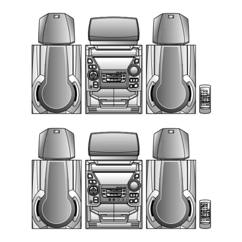
Sharp
Sharp XL-UR5H User manual