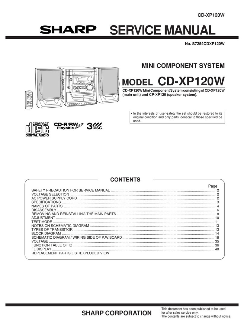
Sharp XL-510H User manual

XL-510H/CP-510
~
SHARP
SERVICE
MANUAL
PR
a
el
No.
$8763XL51
OH//
XL-510H
CP-510
COMPACT
XL-510H
and
CP-510
constitute
XL-510H.
(5
«
In
the
interests
of
user-safety
the
set
should
be
restored
to
its
original
dlti
d
only
parts
identical
to
th
ified
should
b
d.
DIGITAL
AUDIO
R'D'S
condition
and
only
parts
loentica:
to
Those
Spec!
led
snou
e
Use
The
machine
XL-510H/CP-510
is
a
modification
of
XL-
515H/CP-515
by
providing
the
SRS
function.
Its
performance
and
operation
are
identical
with
those
of
XL-515H/CP-515.
For
details
refex
fo
the
service
manual
(No.
S8762XL515H/
/)
for
XL-515H/CP-515.
XL-515H/CP-515
OPERATION
MANUAL
REMOVING
AND
REINSTALLING
THE
MAIN
PARTS
..
8
ADJUSTMENT
9
WAVEFORMS
OF CD
CIRCUIT
TROUBLESHOOTING
(CD
SECTION)
FUNCTION
TABLE
OF
IC
LCD
SEGMENT
p
CONTENTS
:
SAFETY
PRECAUTION
FOR
SERVICE
MANUAL
..........:cccceeneseseceneeerettcnenen
regeseneeneneetanseeeestananenesanensaeaersnereinarenaaeeeanaeny
SPECIFICATIONS.
.....ccccccccceccescscessesscecscecececeseneeneeecaeeccaeasnauceenesesaasarscsseasenueransresteaeansneansaneeseneesscenaneersarasesiossaceceeyanentensenans
NAMES
OF
PARUS
sjeiccccectesktrccoscccnent,
seceneaeseeaesesstecseccecesssusscsucceseesesesesacausneasusnsensosessntanesauseeeusesausesseasacaeanenseaesegenseesesenseens
DISASSEMBLY
.......ccccceccceccesssseseeesscccceeseeecceeccseeecenseenaesnesneseseeserersaeeessnaesecgenecesenacsraenagensuesncenseans
ser
aeensensneneneatanancestrarysase
ed
BLOCK
DIAGRAM
.uc...:ccsccceceecccoccessccececccceresssnscecessneeseteesaepeessnnnaeseecoeestsnencoeensestensnauaacurcarsegsaesenansnsesensneaeeessneneaeesaeatenaaeas
-
SCHEMATIC
DIAGRAM
/
WIRING
SIDE
OF
P.W.BOARD
J...
ceceeseeeesssneecoensneeneenetrrnteseeneensaranenpeneeeeeseaneanenentnnnanees
NFO
TAGE
once
cesta
feces
ced
outcast
ene
gd
adlon
Wedsvsa
aie
obs
eect
beicahscta
glands
di
ledithiat
buen
nuda
nae
bB
SONG
H
DS
NOTES
ON
SCHEMATIC
DIAGRAM
........c:cccccsceesscceeeseneessceecerrensessnensssueseanaaecaerenees
se
naeeaaenauerenaneatnnaeseacaneetnnienennen
sees
eeneees
TYPE
OF
TRANSISTOR
AND
LED
uo...
cee
ecceeceeereneececeeeoscentenneeeenneeeseauseeesanesnsnacecsacesteapaeeneananeserseseaeeeasecsgensnaneanteniegts
REPLACEMENT
PARTS
LIST/EXPLODED
VIEW
(
|
|
This
document
has
been
published
to
be
used
SH
ARP
CORPO
R
ATION
for
after
sales
service
only.
|
The
contenis
are
subject
to
change
without
notic
|
XL-510H/CP-510
SAFETY
PRECAUTION
FOR
SERVICE
MANUAL
Precaution
to
be
taken
when
replacing
and
servicing
the
Laser
Pickup.
The
AEL
(Accessible
Emission
Level)
of
Laser
Power
Output
for
this
model
is
specified
to
be
tower
than
Class
|
Requirements.
However,
the
following
precautions
must
be
observed
during
servicing
to
protect
your
eyes
against
exposure
to
the
Laser
beam
(1)
When
the
cabinet
has
been
removed,
the
poweris
turned
on
withouta
compact
disc,
and
the
Pickup
is
on
a
position
outer
than
the
lead-in
position,
the
Laser
will
light
for
several
seconds
to
detect
a
disc.
Do
not
look
into
the
Pickup
Lens.
(2)
The
Laser
Power
Output
of
the
Pickup
inside
the
unit
and
re
(3)
No
adjustment
to
the
Laser
Power
should
be
attempted
whe
(4)
Under
no
circumstances
look
directly
into
the
Pickup
Lens
at
any
time.
(5)
CAUTION
-
Use
of
controls
or
adjustments,
or
performance
of
procedures
other
than
those
specified
herein
may
result
in
hazardous
radiation
exposure.
CAUTION-INVISIBLE
LASER
RADIATION
WHEN
OPEN,
DO
NOT
STARE
INTO
BEAM
OR
VIEW
DIRECTLY
WITH
OPTICAL
INSTRUMENTS.
VARNING-OSYNLIG
LASERSTRALNING
NAR
DENNA
DEE,
IJ
IN
1
STRALEN
OCH
BETRAKTA
EF
STRALEN
MED
OMSKA
INSTRUMENT.
ADVERSEL-USYNLIO
LASERSTRALING
VED
AJJNING.
$8
IKKI2
IND
I
STRALEN-HELLER
IKKE
MED
OPNSKE
INSTRUMENTER.
YARO!
AVATTAESSA
OLET
ALTONA
NAKYMATON
LASPRSWITLYLLIE
ALA
TUNOTA
SATEESEEN
ALAKA
KATSO
SIA
OPTISEN
LATIEEN
LAPL
VARNINU-OSYNLIG,
LASERSTRALNING
NAR
DENNA
DEL
AR
OPPNAL
STIRRA
ESIN
[
STRALEN
INSTRUMENT,
ADVERSEL-USYNLIG
|.ASERSTRALING
NAR
DEKSOL
APNIS.
ATTRA
IKRE
INN
|
STRALEN
FLLER
SE
DIREKTE
MED
OPTISKE
INSTRUMENT,
OF.
AR
OPENAD,
SITRRA
t
,
OCH
BETRAXTA
13f
STRALEN
GHNOM
OPTISKT
placement
service
parts
have
already
been
adjusted
prior
to
shipping.
n
replacing
or
servicing
the
Pickup.
CLASS
ft
LASER
PRODUCT
APPAREIL
A
LASER
DE
CLASSE
1
PRODUCTG
LASER
DE
GLASE
|
LASER
KLASSE
t
LUOKAN
1
LASERLAITE
KLASS
1
LASERAPPAHAT
LASER
TRIDY
1
LASER
TRIEDY
1
VAROITUS!
LAITTEEN
KAYTTAMINEN
MUULLA
KUIN
TASSA
KAYTTOOHJEESSA
MAINITULLA
TAVALLA
SAATTAA
ALTISTAA
KAYTTAJAN
TURVALLISUUSLUOKAN
1
YLITTAVALLE
NAKYMATTOMALLE
LASERSATEILYLLE.
VARNING
-
OM
APPARATEN
ANVANDS
PA
ANNAT
SATT
AN
|
DENNA
BRUKSANVISNING
SPECIFICERAS.
KAN
ANVANDAREN
UTSATTAS
FOR
OSYNLIG
LASERSTRALNING,
SOM
OVERSKRIDER
GRANSEN
FOR
LASERKLASS
1.
FOR
A
COMPLETE
DESCRIPTION
OF
THE
OPERATION
OF
THIS
UNIT,
PLEASE
REFER
TO
THE
OPERATION
MANUAL.
XL-510H
@
General
Power
source:
Power
consumption:
Dimensions:
Weight:
@
Amplifier
section
Output
power:
Output
terminals:
@
Tuner
section
Frequency
range:
AC
230
V,
50
Hz
52W
Width;
160
mm
(6-5/16")
Height;
240
mm
(9-1/2")
Depth;
250
mm
(9-7/8")
2.6
kg
(5.7
Ibs.)
PMPO;
28
W
(total)
MPO;
14
W
(7
W
+7
W)
(DIN
45
324)
RMS;
10
W
(5
W
+
5
W)
(DIN
45
324)
Speakers;
4
ohms
Headphones;
16-50
ohms
(recommended;
32
ohms)
FM;
87.5-
108
MHz
-
MW;
522
-
1,620
kHz
LW;
153-281
kHz
@
Compact
disc
player
section
Type:
Signal
readout:
D/A
Converter:
Filter:
Compact
disc
player
Non-contact,
3-beam
semi-conductor
laser
pickup
1-bit
D/A
converter
8-times
oversampling
digital
filter
SPECIFICATIONS
re
ne
Frequency
response:
20
-
20,000
Hz
Wow
and
flutter:
Unmeasurable
{less
than
0.001%
W.peak)
@
Cassette
deck
section
Frequency
response:
50
-
14,000
Hz
(Normal
tape)
Signal/noise
ratio:
50
dB
Wow
and
flutter:
0.3
%
(DIN
45
511)
CP-510
Type:
Full
lange
speaker
system
Speakers:
10
cm
(4")
full
-range
speaker
Rated
input
power:
5
WwW
Maximum
input
power:
10W
Impedance:
4
ohms
Dimensions:
Width;
145
mm
(5-3/4")
Height;
240
mm
(9-1/2")
Depth;
183
mm
(7-1/4")
Weight:
1.1
kg
(2.4
[bs.}/each
Specifications
for
this
model
are
subject
to
change
without
prior
notice.

XL-510H/CP-510
2
NAMES
OF
PARTS
|
@
Front
Panel
Timer
Indicator
12
3 4 5 6
v4
8
9
.
Record
Indicator
Sleep
Indicator
©
REG
SLEEP
RANDOM
MEMORY
RDS
TP
TA
ST
cone
a
eee
mom
monn
shtl
tLtLLLt
Live
.
Random
Indicator
.
Memory
Indicator
.
RDS
Indicator
Traffic
Programme
Indicator
Traffic
Announcement
Indicator
FM
Stereo
Mode
Indicator
Play
Indicator
.
Repeat
Indicator
12.
Function/Band/Track
Number
Indicator
.
FM
Stereo
Indicator
.
CD
Compartment
15.
Display
Mode
Selector
Button
46.
On/Stand-by
Switch
17.
ASPM
Button
18.
Remote
Control
Sensor
)
19.
Programme
Type/Traffic
Programme
Search
Button
20.
Record
Pause/Beat
Cancel
Button
21.
Memory/Set
Button
22.
(CD)
Track
Down/Review
Button
(TAPE)
Rewind
Button
(TUNER)
Preset
Down
Button
23.
Headphone
Socket
24.
CD
Eject
Button
25.
Function
Selector
Button
26.
Band
Selector
Button
27.
Extra
Bass/Equalizer
Mode
Button
28.
Volume
Up/Down
Buttons
29.
(CD)
Play/Pause
Button
(TAPE)
Play
Button
(TUNER)
Tuning
Up
Button
30.
(CD/TAPE)
Stop
Button
(TUNER)
Clear
Button
31.
(CD)
Track
Up/Cue
Button
(TAPE)
Fast
Forward
Button
(TUNER)
Preset
Up
Button
32.
Cassette
Compartment
CHONOAEYNo
—_k
ok
=
©
a
=
fa
OO
1
ee
ee
ae
ee
ma
—_—_ooOOOOO
To
=vannnnno
Oo000000
-
OO
@
Rear
Panel
1.
AC
Power
Input
Socket
2,
FM
75
ohms
Aerial
Socket
3.
MW/LW
Loop
Aerial
Input
Socket
4.
Speaker
Terminals
ole
Ah
Lt

XL-510H/CP-510
CP-510
i
Speaker
Section
1.
Full-Range
Speaker
2.
Bass
Reflex
Duct
3.
Speaker
Wire
XL-510H
@
Remote
Control
1.
Remote
Control
Transmitter
LED
2.
On/Stand-by
Button
3.
(CD)
Repeat/Random
Button
4.
(CD/TUNER)
Memory/Set
Button
5.
(CD/TUNER)
Clear
Button
6.
Timer/Set
Button
7.
Sleep
Button
8.
(CD/TAPE)
Stop
Button
9.
(CD)
Play/Pause
Button
(TAPE)
Play
Button
10.
(CD)
Track
Up/Cue
Button
(TAPE)
Fast
Forward
Button
(TUNER)
Preset
Up
Button
11.
(CD)
Track
Down/Review
Button
(TAPE)
Rewind
Button
(TUNER)
Preset
Down
Button
12.
Tuning
Up/Down
Buttons
13.
Timer
Button
14.
Timer
Up/Down
Buttons
15.
Function
Selector
Button
16.
Band
Selector
Button
17.
Extra
Bass/Equalizer
Mode
Button
18.
Volume
Up/Down
Buttons

XL-510H/CP-510
DISASSEMBLY
Caution
on
Disassembly
Follow
the
below-mentioned
notes
when
disassembling
the
unit
and
reassembling
it,
to
keep
it
safe
and
ensure
excellent
performance:
1.
Take
cassette
tape
and
compact
disc
out
of
the
unit.
2.
Be
sure
to
remove
the
power
supply
plug
from
the
wall
outlet
before
starting
to
disassemble
the
unit.
3.
Take
off
nylon
bands
or
wire
holders
where
they
need
be
removed
when
disassembling
the
unit.
After
servicing
the
unit,
be
sure
to
rearrange
the
leads
where
they
were
before
disassembling.
4.
Take
suffcient
care
on
static
electricity
of
integrated
circuits
and
other
circuits
when
servicing.
XL-510H
STEP
REMOVAL
PROCEDURE
1
|Top
Cabinet
»
SOLOW
..cceeeseceeeee
(AT)
x4
.
Socket
..............-.-
2
|Side
Panel
:
(Left/Right)
.
SCKOW
weccceeceeceeeeeee
Back
Board
4
Front
Panel
5
|Display
PWB/
CD
Servo
PWB
Main
PWB
.
SCTOW
oo...
eeceeee
eee
.
Socket
wu...
eee
ower
Supply
PWB}1.
fe
4
Tape
Mechanism
‘
|
9
|CD
Mechanism
«
SOTOW
visisecinensaesaass
(D1)
x4
SOGCKSD
sisiissssencnccs
:
Screw
Jabsotekasutaeness
.
Socket
wc...
4
NO
tie:
hisesteccccccidesssieee
3.
SCPEW
woccccecceseeceseeees
CP-510
Speaker
Box
Net
(A1x1)
Direction
of
handle
Figure
5-5
XL-510H
»
_{A1)x2
@
43x10mm
(B1}x3
a3xi0mm
(A1)x1
e@3x12mm
%
gD
(B1)x2
Panel
a3x10mm
ers
(C1)X1
“~~
Rear
Panel
eoxvonn
os
,
ee
(B1)x2
Side
Panel
(C1)x2
@3x10mm
23x10mm
Figure
5-1
(E1}x6
@3x10mm
Display
PW8
Se
(D1)x1
~*~
g3x1
omm
SF
gy
(F1)x1
93x10mm
CD
Servo
PWB
(D1)x1
“@p
g3x10mm
Power
Transformer
Figure
5-2
Front
Panel
(H1}x4
gaxiomm
Figure
5-3
(J4)x3
g2.6x10mm
Figure
5-4

XL-510H/CP-510
2
S
IC70t
IXOISOAW
i
KEY
t
&)
Sw702-SW707
HIN
Bd
SW710-SW71B
)
5)
-
Qa
|
9
|
'
LED701-LeD71E
pe
ES)
14
FS
Ey
—_\
#
ey)
mo
a
CD
ewrat
RxX7O
RESET
BOO
———
er
ae
(ole
|
o.
ca
U-CON
4S¥
one
SWITCHING
eDe
One
SWITCHING
AN
mid
gg
i
rer
*
eS
Figure
6
BLOCK
DIAGRAM
(1/4)
=

Sw70t
CD
EJECT
eS
eT
ere
ey
ERVO
Ea!
=
STATUS
'
rs
re
|
CD+5V
a
!
o} 68
as
A
S|
[QO@O)}rrso1
TEST
POINT
|
|
——e
I
($16.2¥)
o-@)
FAEGULATOA
(3)
~a—-CD+5V
FOCUS
TRACKING
SERVO
CONTROL
it
‘ei
ae)
ry
6
i
Py
did,
G-GND
R
:
enpafp—
ine
i
xs
2a
eae
ee
an
zh
XB01
A-GND
CD
L-Ct
CD
A-CH
XL-510H/CP-510
=
oa
M
GND
i
Zz
S45.2V
@
<=
@
=
©
oO
2
=
(>
\e
3)
On)
6)
1)
{f)
@)
)
4)
@)
@)
@
;
o
Li)
1-CONSV
-
i
o}
|4
z
SWITCHING
=
ra
TAPE
MOTOR
DAIVER
|
SWTCHING
M-12aV¥
SOLENOID
SWITCHING
i
DRIVER,
|
3
Is
|
5
GOOCOOD
aisor
Cty]
ty]
AOOMADA|
cnseo1
(DOOOOOOD)
CNP901
PHaOt
Piste
1
pHEVEN
JON

XL-510H/CP-510
SWITCHING
=a
a
[301
FM
MUTE
LEVEL
Ke
VA3SI
MWILW
ANT.
¥
aa
xas1
Ey
AM
OSS
OUT
uw
Ss
AM
MWILW
Osc,
Gh
at
SOP
T3035
LN
oD
A
‘NN;
“=O
e
ase
a
Lao
4
Q
==
LS
it
VOLTAGE
REGULATOR
20354
+8V¥
Avolo
+12V
aNvena
A-GNO
TERMINAL
bs
£
ae
(ce
AUDIO
+12
:
VOLTAGE
REGULATGA
6)
Q)
a
80
FW301
S0007W
FM
FRONT
END
CEL
IC101
SWITCHING
1
-
!
!
BA3126N
a
F
pe
=
|
|
BASI2ON
erm
fo-—~L
sects
Jenne
:
!
7
RECORDIPLAYBAK
HE,
L-CH
fs)
228
Oy
|
=
ERASE
HEAD
Q151
L154
BIAS
OSC.
C7)
SWITCHING
Q154
|
BEAT
CANCEL
Q155
|
SWITCHING
REC
BIAS
CONT
A-CAN
(iz)
REC
SWITCHING
Figure
8
BLOCK
DIAGRAM
(3/4)
=2—

+6¥
AMP,
x52
ADS
DATA
Cd
456KHz
ADS
CLK
£4 G3
>
GMA
CEHsi4is
8
fz
6
i.
5
c
=
F
Ese
£
io
iv”
wo
8
a
8
zh
o
Das
© ©
OO
® @
(2)
FM
+8
45Y
Treat
ings
VOLTAGE
REGURATER
B-MUTE
JDIO
+42V
STEREO
CE
DI
cL
DO
REC
L
SEC
R
TAPES
TAPER
VOLTAGE
REGULATOR
VOLTAGE
REGULATOR
MECH
+42¥
(oso)
é
AUDIO
+12¥
Els
=<
a
Ww
“laslaselta
det
dade)
3c00UE3
a
alae]
36
REGULATOR
alg
z
<alz|
Slele
P
(ox)
DOOOOOOVO
V7
‘
TO CD
SERVO
PWB
(2)09
|
CNPGO3
—
soe,
enpsx2[DOOOOOOOOGORYOOSGEOE
DOGOOGDOOGOLHLOEGEOE
Figure
9
BLOCK
DIAGRAM
(4/4)
i
=
se
XL-510H/CP-510
R-CH
K-BASS/GRAPH|C
EQUALIZER
LC75394E
AUDIO
PROCESSOR
FUNCTION
CONTROL
Vol
UBIO
CONTROL
eno
tee
G-EQ
CONTROL
L-CH
X-BASS/GRAPHIC
EQUALIZER
S0601
SPEAKER
TERMINAL
J608
O
HEADPHONES
D6s1
-
DES4
ros
8
T254
&
L250v
6
[
ere
err)
POWER
TRANSFORMER
AG
SOCKET
23a0V,50Hz

XL-510H/CP-510
2
2
—~
a
4
x
|
{zx
e
=
S|
3
x
ut
EI
80
os
ix)
Sn
2
Reis
7
Mi
cede
=
db
i9éH
MLOe4H
ME
BS2y
ey
ey
Me
Lad
4
a
a
+
a3
Ea
id
a
:
:
COMPUTER
ag
ow
IC7o1
o1soAW
5
a5
i"
Rag
Ut
iX'
5
g
=
LT
a
+B
a
+B
ce
7
2
A
AE
aes
ee
(DC
OE
Sh
yA
fy
eh
ye
pe
i]
Re
[x
ie
3
t—+—
2
se
=
a
a
=
a
:
§)
IEG
Gh
aede
Pca
;
ee@a
FF
EF
T°
AHA
xi
o
Lae
|
t
|
+H!
|
ee
)
eee
|
TT
4
|}
|
oe
eS
m
2]
|
ee
ee
i
t
7
|
ae
|
3
ro
A
oO
z
a
Rg
ir
oo
5B
;
ale
=
!
1
a)
ee
ee
ith
7
a,
O_O
a
8
2
:
Pe
1
—+—_____-
ee
¢
ea
a
la
=
[OL
zee
|
|
_|
GN
rh
yy
ek
oy
*
NOTES
ON
SCHEMATIC
DIAGRAM
can
be
found
on
page
18.
aK
aK
a4
G
Sa
710
2k
750
t
#720
1.8K
Ae
|
10K
+8
SPs
=
|
|
tc
eI
©899@0
ma
-
za
O80GG0909
-
=
6G806800
OaRRE
HUTT
TTY
ti
TT ty
OOSCGRO]
msn
r0sn2|OOOSCCOOGE]
xssn2[(GGOOCOS]
SWITCHING
WB-A
swri7
PTY.TI
SEAACH
swris
ASPM
DISPLAY
MODE
———
5
ee
1
DISPLAY
P
Sw7is
H
8
1
SI99GA
fe
29.9896)
toe
‘O
pase
Fags
®;
O7og
KT03199
GA
ge
SWITCHING
f
10.7'
~
Ad
"LEO
PWE-A4
Figure
10
SCHEMATIC
DIAGRAM
(1/4)
~10-

XL-510H/CP-510
|
CD
LID
SWITCHPWB-A7___
—=;
Lal
Hear
uz]
2
,
es
delay
Jag,
8
#8
oO
3/5\-\
—
;
re
|
a
4
(060.
e
coe
ae
!
co
Bigot
4B
a
CD
SERVO
PWB-A2
}
BWeo1
RECORD
PREVENTION
TAPE
MECHANISM
PHso1
OOOOOQY|
Cnss01
Mii
zl
GOOQOO)
PWB-C
HHT
ili
oss
Soagqgd
of§=$#
_=WAMga
saggy
ctsaaaqnong
mill
a
x
r
c
ag
So
Eamy
ts
g
53
a
3
<
388
cca
|
iB
ale
#
ate
B
OS
me
+8
|
ae
Ene
re
I
—
a
es
as
ee]
ann
Es
ees
;_
+B
|
u-
u-GONS
Buso
+B
ONTROL
TC9284BF
SERVO/SIGNAL
C
O718
RLi04A4
we
CD
SIGNAL
'
h
||
|
it
|
||
i
|
1
.
|
|
Mae
SAH
ep)
3)
wa
|
hs
ee
7
B
||
|
{ees
vit
|
|
es
a
EE
te
|}
ET
POE
|
mx
on
1]
i
ae
Be
an
eh
aa!
oualS
!
my
S
4~
=
Willilitsea=see
.
2a
at
|
||
(man
=.
i
#3
se
a
tal
la
Be
e|=l=|</Sle}=]<1=!</xI=
Gi
@Q)*
Et
sle]2a[e]2]ei<|elal—|2
&
|
S/S
(EIFISISISIEIBIBIEIE
wn~
¥
Patni.
——.
_
ee
ae
Oe
Oe
a
ee
ee
|
=44
=
Figure
11
SCHEMATIC
DIAGRAM
(2/4)
ove
wl ee
ee

XL-510H/CP-510
f
3
g
38
o&
og
58
8 5
:
Leper
y
3
ine
tal
HRS
ERASE
HEAD
a1s2
KTAI266GR
rcltd
O1ba
$99GR
KT
Casa
UDBSIEDIN
SGLEOLM
=)
35)
rS10
ite)
HOMAS
SNIHOUMS.
O
LYSE
“BD:
ia
*
NOTES
ON
SCHEMATIC
DIAGRAM
can
be
found
on
page
18.
Figure
12
SCHEMATIC
DIAGRAM
(3/4)
aioe

ON
~!
——
a
ap
~~"
XL-510H/CP-510
evden
vecerrnced
te
aurcecer
cee
eceertessdy
A
wu
scereren
ee
EEE
ec
ek
et
SY
Wee
Ee
nowercorrne
me
waceced:
Ne
Saas
a
Re
9388
58
a
Rava
Saas
100K
————
D4ot
=
age
156133
133133
oc6P(ak)
POWER
AMP.
”
Dp
J
a
iS
8°_R-CH_GND
(+)|
SP_A-CH
a
,
g
HEADPHONES
:
&
PWB-AS
Be
'
Aiea2
HEADPHONES;
i
onesie
nig?
eee.
.)
\
a
_
Fase
a7oue
-c
ago
I
:
:
Wes
eed
i
mane.
om
820!
oo or
Bigs
fPAIAREn
ae
sabiley
coy
I
Gases
CPOE
ca
crac
ee
a
er
enerretr
te
rennannne
ve
ecernen
e
’
:
qed
LE
:
Ts5t
Ca51-COM:O1
+8
’
taaRSeonhen
0651-0054:
RL2o4F
'
eyes
H
Toase
1
3
REGULATOR
ee
'
«
|
a
y
+
Qeo4
|voLTAGE
———
i
G2
i
eS
rien
to
ty
Reo
G2
:
|
A
H
i
|
‘47
7"
een
|
tans!
i
nN
B20
|
7
ness
|
4,
80551
:
et
ae
j
|
POWER
SUPPLY
|
|
a
‘
TO
CD
SERVO
PWA
are
|
RWE
AG
4
OCD
SERVO
PW
a
Us
ee
a
ee
Kcuusccceascuane
t
oe.
he
ee
ee
es
When
Serving
pay
atiention
as
the
area
enclosed
by
thls
tne
(mm
xm
8}
1s
direcily
connected
with
AC
main
voltage.
ee
ge
ee
Ae
I
Figure
13
SCHEMATIC
DIAGRAM
(4/4)
ae
Fes

XL-510H/CP-510
POWER
SUPPLY
PWB-A6
When
Serving
pay
attention
as
the
area
enclosed
by
this Jine
{mma
mma)
is
directly
connected
with
AC
main
voltage.
|
se
6
ke
CU
YL
ah
eae
POWER
a
“-*
lenposy
TRANSFOMER
CNSB51
PI66-E
—
AC
SOCKET
AC
230V,50Hz
COLOR
TABLE
Swo9o1
RECORD
PREVENTION
M901
SOLENOID
TAPE
MOTOR
SOL901
PICKUP
UNIT
SPINDLE
MOTOR
MB02
belie
delle
le
eee
Te
eee
ee
eee
ee
Figure
14
WIRING
SIDE
OF
P.W.BOARD
(1/3)
me,

XL-510H/CP-510
DISPLAY
PWB-A3
CD
LID
SWITCH
PWB-A7
se)
CNS901
VAIN
Es
:
“>
IGNP603
Onan
eset
et.
foc]
Oem
ptt
:
itd
%
P16
1-6
yO
MAIN
PWB
>
[onPe02]
i:
>
P16
1-E
sewer
ew
eren
|
CNS801
4
ee
et
Dt
tebe
Figure
15
WIRING
SIDE
OF
P.W.BOARD
(2/3)
S45=

XL-510H/CP-510
COLOR
TABLE
RECORD/PLAYBACK
READCON)
ERASE
HEAD(102)
HEADPHONES
PWB-AS
HEADPHONES
FROM
FROM
CO
SERVO
PWBI
P15
12-G
POWER
TRANSFOMER
3
$0301
ANTENNA
CNP3O1
TERMINAL
AM
LOOP
L
speaxer
sox
L
speaker
Box
J
ANTENNA
L-CH
F-CH
SPEAKER
TERMINAL
Figure
16
WIRING
SIDE
OF
P.W.BOARD
(3/3)
S16

XL-510H/CP-510
VOLTAGE
VOLTAGE
=
|
Se
i-
a
f=
_-
j=
j=
BV
=
OMS
cad
et
=
ae
|=
an
j—
pov
[sv
Lov,
2.4V
2.2V
21V¥
O
=
—!
>j]>
>|>
>|
>|
>
>|
>|
>
>
>
>)
>l>|>|>]>]
>]
>
>|>
>
>|>
> >
O
[>|
214]
>] 8] %]
>] >|
>]
>]
>] >] >]
8]
a]
>]
2)
8]
Sl
Sl)
Fl
SEIS
ISG
Slalclaia
bal
he
=f]
2]
6]
>>]
>|
>| 7]
1]
©
ti>
317/2|.18|>/>/>/>]2]
8/5
>
>
S
|S]
ai]
el]
B]
cd}
cl]
S|
HY
tH]
in]
HY]
S|
S]
+]
S|]
3]
Sw]
YO]
]
Cfo]
Of
of
ti
AT
Nae
NEO
NN
NIN
OPO
O;ol,
cocina
nN
o
WINININ|
NOPOlofo;
ole]
a
a
oa
>
ole
BM
Cl]
AN]
09}
tI
LO]
COP.
|
CG]
Oa]
GO)
rj
CN
9)
CO)
[01
Oo)
SO]
T/L]
coy
MS
D/O
=
roa]
<a
ite]
i
Ol]
EN]
Oo)
S|
LOO)
co)
&
TT]
O38
COI
StL)
OT
h.7
colo)
TON]
OD)
ST]
LO
pod
Coe
Deed
Dod
ed
oe
ot
ed
el
he
CD
NY
AN
CU]
09)
09
09)
CD]
2]
OD
OO)
il
oe
fel
eed
fee
ae
fed
ed
Ded
IOS
ENA
QUE
QU
02]
03]
6D]
2]
CDT
OD]
Pd
ad ed
Pad
Pred
Part
>
>|>
pl>l>
>
>
>|>
p>]>|>
Pl
>|>|>)
>
>
Ee
eal
ad
Fd
Bo)
6-0)
Bo]
a
009]
0D
o00
od
Wd
ey
Ded
De
De
Od
ed ed
Ded
Ded
Rar
Bed
Drs
aed
et
Dd
ae
Bars
ard
td
oe
Bet
Bcd
ad
Bod
A]
pasty
ny
Bl
Al
aida]
Nl
AAI
NI
AIA
Ol
i]
BA]
NN]
NO]
EE]
cy
cet
oc)
ow
Os
Oo
NY]
CO)
sr]
Lo
™
AO
Nw
W/L]
CO]
|
CO]
Oo]
GS]
ee
NI
Got]
LO
h]c0
WI]
C3)
<r]
Py>|>
>
boned
Bed
Pd
ed
Poe Pad
Pe
>l>|>)>
>l>i>
SielelelelSlS/SlS/
22/212
>
sol
| |
>|
=|
>|
>|
>]
=]
2]
2]
Bl]
o|
&]
>|
>|]
B12
14]
|
9
|]
/@
|
[lig
||
Jo
[GB
alee
hailed
laa]
caf
cal
cd
|
ca
cc|
cu]
oi]
oa]
oa
SlLSlSlSlS]
Sl
HS]
s]
sho]
a]
S|
$F]
S/S]
a]
appa
NININTN
NIN
TA
NPN
TNA
EATON
NEN
ON
is}
—|cu]oad
s+
N00
|
col
st]
col
ne
O}
—]
ou] co] st}
Lo]
<0}
MB]
ca]
on]
O]
bh]
0
—]
Qu)
co]
st] to]
col
=
Up}
in}
ta
|p
iP)
(Ve)
0]
£0}
<5]
cD]
ca]
coco
BINDS
S|
SIS
TS]
|S]
|
00]
00
co}
co
>]
&3|
Oh]
Ga]
dd]
Ta]
o>
2
Lu
1¢804
AES
al
B/S
i]
S|
oa]
By
a
i]
ov
[AU
OO}
TELA]
CO]
100]
o>
a1]
StL
coy
[o))
s-|
Qu
ooy
st
MS
Oo]
|
CN]
OD)
PLO]
wo
fea} Pap)
a
Sle]
bet
ht]
|
ett]
|]
Lo]
C9]
ca]
wa]
uf
6]
ta]
tat]
©}
<0]
CO]
oO]
co
rs) Fre
RO
Fs
TNS
Fd
9
os
a]
uw
IC801
2.2
iv
2Vv
5.7
5.8V
22
7.7
>
>
>
Hier
ad
ocd
Ba
:
Ae
Pad
Pd
oop
SS
|
>
>|Sp>y%\
Kfpolso;
rin
TLOIN)
OrNjolr
N
N
> >
>l>l>
Sl>l>l>
>
>>
7)
Pd
f-d
Dead
Ae)
ra
9)
in]
S]
st]
]
SB)
Op
Nec
SAyS
hase
ees
ele
lOlK|NIAN
eR
|
ep
O,oO;,o
ojo
NENT
N
|
Ki
NEN
LO
2.5V
2.5V
2.5V
2.5V
2.5V
2.5V
IC604
>
OLTAG
6V
BY
43V
5V
0.15V
0.03V
3.65V
>l>fe[>
>|
>]>|l>
>|>
>
>
>
pl>|>[>1>
>l>1>
>
Bl
Ahialin|>|
ela]
B|
S|
Sl]
>|
=1-|
o]
>|
>|
>)
>]
>|
>|
S}
|
ol
epel
eel
elele]
2]
Se)
219]
Sele)
SSIS
SIS
SSS
lal
sie
ail
cdfod}
od]
O|
fal
|
cll
cd]
S|
ol]
ci]
S|
S]
S|
GB]
GB]
D]
HB]
S|
B]
H]
GH]
S|
in]
S|
S/S)
S/O]
ze]
Ol]
s]
st)
Of
io]
st]
Of]
9]
oO)
Of]
|
SO]
1
>
i=]
CY]
09]
st]
40]
Ol
|
co]
cn)
NY
cols
O]
$100]
0>
Mijco)
st]to
OD]
QD)
O}r-|
Cr
19]
co}
B
Oo
)
ao
uy
oO
sp
PERE
EP
RESP
Pee
PPllssiastessesllepisialslesieislelepiie
|
les
Psp
h
lee
sPe
seer
isasiss
Sl>l>l>(F/S12
1212/2
/212IZIZI
ZIBB]
|B)
ps
=]
(>|
[2I2I2zIZIZIRIZIZIZIZIZIZIZIZIE
>
AIRJRIRIATSI
ARTE
RR
SIRIR
So]
[Se]
Pl
polSl>
e]
Fal
JER
SPRTRSISTSISISy
RSS
eis
TSTEPSPSPeypsyeys
Sd
od
oe
ee
od
od
ee
oe
od
od ed
nd
a
od
od
ad
wv
ww
oyo;o
wT
vt
Se
nd
nd
nd
Od
od
ad
ed
Oe
ed
dd
vt
vr
ZO
NY
Od)
tILo]Ole-/
coy
|
oO
pd
bo
Le)
<a]
oO
09)
+Tkn
Lew
Oo
WN
T/LO]
CO]
100]
A)
oO]
sry
ed
m
Fok
Heb
leherlel-beteteletletteitalelelelslelaal
slat
alaltalaatelsitelstlelslelalafaajalalalela
3
a
z
2
=
y
is)
>|
>[>|>
>
>
pl>el>
> >
>
>|>
Sod
Board
Bild
Occ]
Peart
fied
ed
booed
Pd nd
Pd
ed
2]
Si]
2]
DH
o
1
>|=|=|>|>|>|5]>|>|5]@
|
=|
&
@|=
>|%
oTfoy
ol
to)
HLopyo
ol
mya
NINOS
Pat]
IN]
NIN]
CP]
is],
Np],
Oo]
cl
co
iN
NIO
Ww
>
>
nN
wv
oy,
Nyo
ea)
a
I]
03]
st]
10)
<O]
1)
cO
=)
NS
=)
AO
®
S|
|
:
34}
15}
to)
9]
tf
1] 1)
UG]
1G] ts]
|
Un]
UG]
)
19) wy}
ey
Wo)
9)
A
2/3
21
S/S]
a]
S/alS
=
[Sl2/c]
Joa]
e/Slsisla
18]
19
19]
ws ui
1]
GS)
wf
19
6
19]
|
us
=>
|r
wi}
7V
7¥
sVi1.2V
1¥(2.7V
Vv
V(0.9V;
{2.2
0
2
Ww
rd
=
}
1,43V
57V
57V
57V
57V
57V
57V
57V
56V
1.387
>
a
o
57¥
5.57¥
5.56V
5.56V
5.56V
5.56V
5,
5
5
§
5
5.55V
IG204
>
=O
az
se

XL-510H/CP-510
NOTES
ON
SCHEMATIC
DIAGRAM
e
Resistor:
To
differentiate
the
units
of
resistors,
such
symbol
as
K
and
M
are
used:
the
symbol
K
means
1000
ohm
and
the
symbol
M
means
1000
kohm
and
the
resistor
without
any
symbol
is
ohm-type
resistor.
Besides,
the
one
with
“Fusible”
is
a
fuse
type.
«
Capacitor:
To
indicate
the
unit
of
capacitor,
a
symbol
P
is
used:
this
symbol
P
means
micro-micro-farad
and
the
unit
of
the
capacitor
without
such
a
symbol
is
microfarad.
As
to
electrolytic
capacitor,
the
expression
“capacitance/withstand
voltage”
is
used.
(CH),
(TH),
(RH),
(UJ):
Temperature
compensation
(ML):
Mylar
type
(P.P.):
Polypropylene
type
e
Schematic
diagram
and
Wiring
Side
of
P.W.Board
for
this
model
are
subject
to
change
for
improvement
without
prior
notice.
[REFNO
|
DESCRIPTION
|
POSTON
|
ON
sw707
|
FUNCTION
|
ON—OFF
N—
5
F
sw7i0
|
REC.
PAUSE
:
SW711_
|
MEMORY/SET
ON—OFF
Sw7i2
|
PRESET
DOWN
ON-—OFF
F
2SA1015
GR
2SB562
C
2502001
K
250380
O
23D468
C
KRA107
M
KRC102
M
|
KRA102
M
B
KRC104
M
KTC3199
GR
KTC3203
Y
Kel
2SD2012
Y
FRONT
|
VIEW
tf
|
KRC107
M
HS)
Cay
3)
KTA1266
GR
BCE
¢
The
indicated
voltage
in
each
section
is
the
one
measured
by
Digital
Multimeter
between
such
a
section
and
the
chas-
sis
with
no
signal
given.
1.
In
the
tuner
section,
{
)
indicates
AM
<
>
indicates
FM
stereo
2. in
the
main
section,
a
tape
is
being
played
back.
3.
In
the
deck
section,
a
tape
is
being
played
back.
( )
indicates
the
record
state.
4.
In
the
power
section,
a
tape
is
being
played
back.
5.
In
the
CD
section,
the
CD
is
stopped.
e
Parts
marked
with
“
A,”
(
E
=
==
7)
are
important
for
maintaining
the
safety
of
the
set.
Be
sure
to
replace
these
parts
with
specified
ones
for
maintaining
the
safety
and
performance
of
the
set.
NOE
ON—O
.@)
Oo
O
a
R
FF
204GDTR4
FRONT
VIEW
Pi.
Figure
18
TYPES
OF
TRANSISTOR
AND
LED
S27
6es

XL-510H/CP-510
SHARP
PARTS
GUIDE
MODEL
XL510H
CP-510
“HOW
TO
ORDER
REPLACEMENT
PARTS”
To
have
your
order
filled
promptly
and
correctly,
please
furnish
the
following
information.
1.
MODEL
NUMBER
2.
REF.
No.
3.
PART
NO.
4,
DESCRIPTION
For
location
of
SHARP
Parts
Distributor,
Please
call
Toll-Free;
1-800-BE-SHARP
For
U.S.A.
only
Contact
your
nearest
SHARP
Parts
Distributor
to
order.
*
MARK:
SPARE
PARTS-DELIVERY
SECTION
Explanation
of
capacitors/resistors
parts
codes
Capacitors
Resistors
WO.
sevcaiecscctancaceonins
Ceramic
type
VERE
raiisitiaiectae
Carbon-film
type
MIG
cccitaniesgcvamwtve
Ceramic
type
VRS
woeeeeeeseeeeeees
Carbon-film
type
WOT
cesecsaxrancaamnetvises
Semiconductor
type
VAIN
secsstaassteevbanbnecaa
Metal-film
type
VC
MF
...............
Cylindrical
type
(without
lead
wire)
VRe*
MF
...............
Cylindrical
type
(without
lead
wire)
VC
ee
MN...
eee
Cylindrical
type
(without
lead
wire)
VReeMN...............
Cylindrical
type
(without
lead
wire)
VC
80
TY
sacccceasectinas
Square
type
(without
lead
wire)
VERS
DV
inccntecccvites
Square
type
(without
lead
wire)
VG
60
TQ
srssecessscaass
Square
type
(without
lead
wire)
VR
°°
TQ
..............
Square
type
(without
lead
wire)
VG
68
OY
cectncanteres’
Square
type
(without
lead
wire)
VR
°eCY
.............
Square
type
(without
lead
wire)
VG
TS
a
cistcssnins
Square
type
(without
lead
wire)
MO
OZ
esis
ctnss
sensi
Square
type
(without
lead
wire)
VC
eeeeeeeee
J.
The
13th
character
represents
capacity
difference.
VReeeeeeees
.
The
13th
character
represents
error.
("J"
+5%,
"K"+10%,
"M"
420%,
“N"
+30%,
(“J*
+5%,
"F"
+1%,
"D"
40.5%.)
"C"
£0.25
pF,
“D"
40.5
pF,
'Z"
+80-20%.}
lf
there
are
no
indications
for
other
parts,
the
resistors
are
15%
lf
ihere
are
no
indications
for
the
electrolytic
capacitors,
error
is
+20%.
carbon-fiim
type.
NOTE:
Parts
marked
with
“A\”
are
important
for
maintaining
the
safety
of
the
set.
Be
sure
to
replace
parts
with
specified
ones
for
maintaining
the
safety
and
performance
of
the
set.

XL-510H/CP-510
PRICE
NO.
PARTCODE
x
RANK
XL-510H
INTEGRATED
CIRCUITS
(C101
VHIBA3126N/-1
J
AF
IC102
VHIBA3311L/-1
J.
AK
Ic302
VHILC72131/-1
J
AP
Icg03
VHILA1832//-1
J
AR
IC401
VHILC75394E-1
Jd
AX
10521
VHILA2232//-1
J
AX
IC601
VHILA4600//-1
J
AN
IC701
RH-IXO1ISOAWZZ
J
AY
IC8o1
VHITA2065F/-1
J
AT
Icgo2
VHITC9284BF-1
JAY
IC804
VHIM56748FP-1
J
AR
TRANSISTORS
Q101~106
VSKTC3199GR-1
J
AB
Qi07
VSKRC104M//-1
J
ac
Q151
VS2SC2001-K-1
J
AD
Q152
VSKTA1266GR-1
J
AB
Q153
VSKRC104M//-1
J
AC
Q154,155
VSKTG3199GR-1
J
AB
Qi71
VSKRA102M/-1
J
Ac
Q172
VSKRC102M//-1
J
AC
Q301
VS2SC380-0/-1
J
AC
Q302~304
VSKTC3199GR-1
J
AB
Q351
VSKRC104M//-1
J
Ac
Q360
VSKTA1266GR-1
J
AB
Q362
VSKRA107M//-1
Jo
AE
Q521
VSKTC3199GR-1
J
AB
Q601,602
VSKTC3199GR-1
J
AB
Q603
VSKTGC3199GR-1
J
AB
Q604,605
VS2SD2012Y/-1
J
AF
Q606
VSKTC3199GR-1
J
AB
Q607
VS2SD2012Y/-1
J
AF
Q608
VSKRA102M/-1
J
Ac
Qe6o9
VSKRC107M//-1
J
AC
Q701
VSKRC102M//-1
J
AC
Q702,703
VSKTC3199GR-1
J
AB
Q704
VS2SD468-C/-1
J
AD
Q705
VSKRA1I02M//-1
J
AC
Q706
VSKRC102M//-1
J
AC
Q707
VSKTA1266GR-1
J
AB
Q801
VS2SA1015GA-1
J
AB
Qsei
VS2SD468-C/-1
J
AD
Q301
VSKRC102M//-t
J
AC
qgso2
VS2SB562-C/-1
J
AD
Q903
VSKAC107M/-1
JAC
Qg904
VSKRC102M/-1
J
AC
Q905
VS2SB562-C/-1
J
AD
Q906
VSKRA102M//-1
J
AC
DIODES
D101,102
VHD1S$$133//-1
J
AA
D104~106
VHD1SS133//-1
J
AA
D301
,302
VHD18$133//-1
JAA
D303,304
VHD1SS133//-1
J
AA
D401
,402
VHD1SS133//-1
JAA
D601
VHD1SS133//-1
J
AA
D602~604
VHD1S$133//-1
J
AA
,D651~654
VHDRL204F/-1
J
AC
D718
VHDRL104A//-1
J
AB
D720-~-723
VHD18$133//-1
J
AA
De01
VHDRLi04A//-1
J
AB
D901~903
VHD1$S8133//-1
JAA
LED701-715
VHP204GDTR4-v
J
AD
PH901
VHPI31535CD-1
J
AG
VvD301
VHCKV1236223F
J
AS
ZD351
VHEUZ5R1BSB-1
J
AA
20521
VHEUZSRIBSB-1
J
AA
ZD601
VHEUZ130BSA-1
J
ZD602
VHEUZ7R5BSC-1
J
AA
ZD701
VHEUZSA3BSB-1
J
AB
DESCRIPTION
Head
Selector,BA3126N
REC./P.B.Equalizer
Amp.,BA3311L
PLL
(Tuner},LC72131
FM
IF
Det/FM
Mpx./
AM
1F,LA1832
Audio
Processor
LC75394E
RDS,LA2232
Power
Amp.,LA4600
System
Microcomputer,|IXO1S0AW
Servo
Amp.,TA2065F
Servo/Signal
Control,
TC9284BF
Focus/Tracking/Spin/Slide
Driver,
M56748FP
Silicon,NPN,KTC3199
GR
Digital,
NPN,KRC104
M
Silicon,NPN,2SC2001
K
Silicon,
PNP,KTA1266
GR
Digital,
NPN,KRC104
M
Silicon,NPN,KTC3199
GR
Digital,
PNP,KRA102
M
Digital,
NPN,
KRC102
M
Silicon,
NPN,2SC380
O
Silicon,NPN,KTC3199
GR
Digital],
NPN,KRC104
M
Silicon,
PNP,KTA1266
GR
Digital,
PNP,KRA107
M
Silicon,
NPN,KTC3199
GR
Silicon,
NPN,KTC3199
GA
Silicon,NPN,KTC3199
GR
Silicon,NPN,2S02012
Y
Silicon,
NPN,KTC3199
GR
Silicon,NPN,2SD2012
Y
Digital,
PNP,KRA102
M
Digital,
NPN,KRC107
M
Digital,
NPN,KRC102
M
Silicon,NPN,KTC3199
GR
Silicon,
NPN,2SD468
C
Digital,
PNP,KRA102
M
Digital,
NPN,KRC102
M
Silicon,
PNP,KTA1266
GR
Silicon,
PNP,2S41015
GA
Silicon,
NPN,2SD468
C
Digitat,NPN,KRC102
M
Silicon,
PNP
,2SB562
C
Digital,
NPN,KRC107
M
Digital,
NPN,KRC102
M
Silicon,
PNP,2SB562
C
Digital,
PNP,KRA102
M
Silicon,
1$S133
Silicon,
1SS133
Silicon,
1SS133
Silicon,1SS133
Silicon,
1SS133
Silicon,1SS133
Silicon,
18S133
Silicon,
AL204F
Silican,RL104A
Silicon,1SS8133
Silicon,
RL104A
Silicon,
1SS133
LED,Green,204GDTR4
Phote
Interrupter
Variable
Capacitance,
KV1236Z23F
Zener,5.1V,UZ5.1BSB
Zener,5.1V,UZ5.1BSB
Zener,
13V,UZ138SA
Zener,7.5V,UZ7.5BSC
Zener,3.3V,UZ3.3BSB
NO.
PARTS
CODE
ZD702
VHEUZ6R2BSC-1
ZD801
VHEUZSR6BSB-1
FILTERS
CF301
,302
RFILFOO72AFZZ
CF351
RFILFOOOSAWZZ
CF352
RFILAOCOSAWZZ
TRANSFORMERS
T3014
RCILA1074AFZZ
T302
RCILADO5S2AWZZ
T305
RCILB1073AFZZ
T306
RCILBOOSBAWZZ
T351
RCILIOOISAWZZ
A\T651
RTRNPO148AWZZ
COILS
Li51
VP-MK331K0000
L341
RBLN-0001AWZZ
L342
VP-DH2R2K0000
351,352
VP-DH101K0000
L353
VP-DHi02K0000
L354
RFILLOGO1AWZZ
L521
VP-DH2R2Kc000
L601
,602
RCILZ0137AFZZ
L603,604
VP-DH100KO0000
L701
VP-DH101K0000
LF651
RCILZOOOBAWZZ
VARIABLE
RESISTORS
VR351
92LVRS103NBMT
VR521
92LVRS472NBMT
VR802
92LVRS104NBMT
VR863
92LVRS104NBMT
VIBRATORS
X351
RCRM-0028AWZZ
X352
RCRSPOOO2ZAWZZ
X621
RGRM-0019AWZZ
X701
RCRM-0029AWZZ
X702
RCRSP0051
AFZZ
X801
92LCRSTL1746AT
CAPACITORS
C101,102
VCKYMN1HB471K
C103,104
VCKYMN1
HB331K
C105,106
VCKYMN1HB271K
C107,108
RC-GZA476AF1C
C109,110
RC-QZ0016AWZZ
C111,112
RC-GZA106AF1C
C113,114
RC-GZA475AF
1E
C115,116
VCTYMN1CX222K
C117
RC-GZA106AF1C
C118
VCTYMNIEF2232
C119,120
VCTYMNiCY
103K
C121,122
VCKYMN1HB820K
C123
RC-GZA2254F1H
C124
RC-GZA476AF
1G
C125
RC-GZA107AF1E
C126
RC-GZA226AF1C
C129,130
RO-GZA475AF1E
C131
VCKYBT1HB821K
C151
VCKYMN1HB181K
C152
VCKYMNIHB102K«
C153
VCQPKA2AA392U
C154
VCQYKA1HM273J
C155
RG-GZA476AF1C
C156
VCKZPA1HF223Z
C301
,302
VCKYPA1HB102K
C322
VCCCMNIHH100J
C323
VOTYMN1EF223Z
C324
VCCUMN1HJ270J
C325
VCKYMN1HB221K
C326
VCCCMN1HH180J
a
*
[
eerk
Qaa
EKcecegwaaiaoac
jE
a
er
ee
a
a
ee
ee
a
SO
SS
a
2
PRICE
RANK
AS
AA
AG
AK
AE
AC
AC
DESCRIPTION
.
Zener,6.2V,UZ6.2BSC
Zener,5.6V,UZ5.6BSB
FM
IF
FM
IF
AM
IF
LW
Antenna
MW
Antenna
LW
Oscillation
MW
Oscillation
AM
IF
Power
330
H,Choke
Balun
2.2
mmH,Peaking
100
WH,Choke
1
mH,Choke
Low
Pass
Filter
2.2
mmH,Peaking
0.29
WH
10
WH,
Choke
100
WWH,Chake
AC
Line
Filter
10
kohm
(B),Semi-VR
[VCO]
4.7
kohms
(B},Semi-VA
[RDS]
100
kohm
(B),Semi-VR
[Tracking
Error
Balance]
190
kohm
(B},Semi-VR
(Focus
Offset]
Ceramic,
Crystal,4.5
MHz
Ceramic,456
kHz
Ceramic,8
MHz
Crystal,32.768
kHz
Crystal,16.93
MHz
470
pF,50V
330
pF,50V
270
pF,50V
47
wF,16V,Electrolytic
0.015
LF,S0V
Electrolytic
10
uF,
16V,Electrolytic
4.7
WF,25V
Electrolytic
0.0022
uF,16V
10
uF,
16V,
Electrolytic
0.022
F,25V
0.01
WF,16V
82
pF,S5S0V
2.2
LF,
50V,
Electrolytic
47
uwF,16V
Electrolytic
100
WF
,25V,Electrolytic
22
WF,
16V
Electrolytic
4.7
|WF,25V
Electrolytic
820
pF,50V
180
pF,50V
0.001
F,50V
0.0039
j1F,100V,
Polypropylene
0.027
uF,50V,Mylar
47
WF,
16V,Etectrolytic
0.022
\F,50V
0.001
WF,S0V
10
pF
(CH),50V
0.022
UF,25V
27
pF
(UJ),
50V
220
pF,50V
18
pF
(CH},50V
This manual suits for next models
1
Table of contents
Other Sharp Stereo System manuals

Sharp
Sharp QT-CD700W User manual

Sharp
Sharp CD-DV999W User manual

Sharp
Sharp CP-XP120H User manual

Sharp
Sharp QT-CD20H User manual

Sharp
Sharp CD-MPX880H User manual

Sharp
Sharp QT-V5E User manual

Sharp
Sharp CD-CH1500 User manual

Sharp
Sharp CD-C430H User manual

Sharp
Sharp XL-HF202PH(S) User manual

Sharp
Sharp MD-X8 User manual

Sharp
Sharp QT-CD180(BL) User manual

Sharp
Sharp CD-C410W User manual

Sharp
Sharp SD-NX10H User manual

Sharp
Sharp XL-1200 User manual

Sharp
Sharp XL-MP80H User manual

Sharp
Sharp XL-DAB102BH User manual

Sharp
Sharp CD-BK1600V User manual

Sharp
Sharp CD-C410H User manual

Sharp
Sharp CD-BP1200W User manual

Sharp
Sharp CD-XP700 User manual