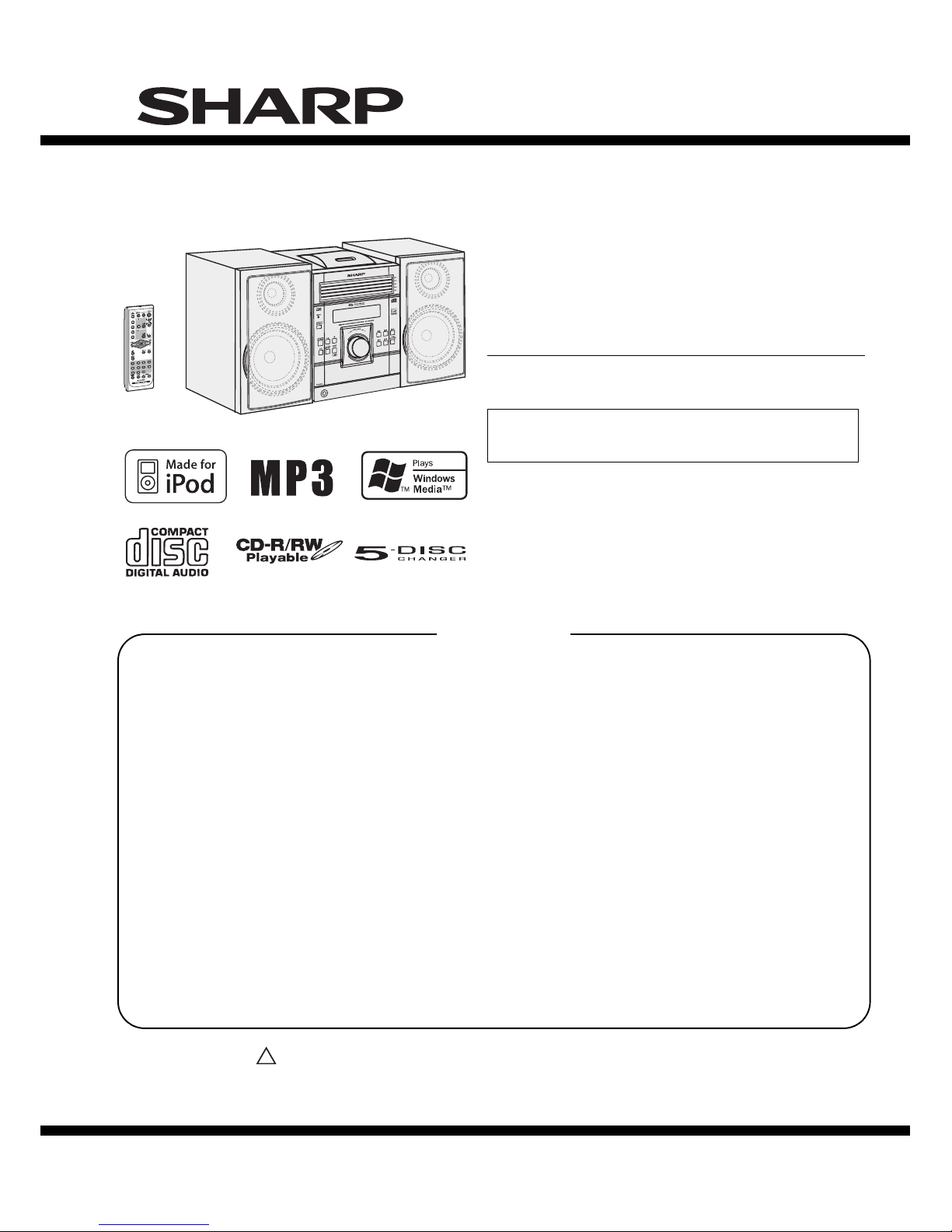
Sharp XL-DK225 User manual

XL-DK225
– 1
This document has been published to be used for
after sales service only.
The contents are subject to change without notice.
VIDEO
/AUX
PRECAUTIONS FOR USING LEAD-FREE SOLDER
CHAPTER 1. GENERAL DESCRIPTION
[1] Important Service Safety Precaution ........... 1-1
[2] Specifications............................................... 1-1
[3] Names Of Parts ........................................... 1-2
CHAPTER 2. ADJUSTMENTS
[1] CD Section .................................................. 2-1
[2] Test Mode .................................................... 2-2
[3] Standard Specification Of Stereo System
Error Message Display Contents ................. 2-4
CHAPTER 3. MECHANICAL DESCRIPTION
[1] Removing And Reinstalling The Main Parts
..................................................................... 3-1
[2] Disassembly ................................................ 3-2
CHAPTER 4. BLOCK DIAGRAM
[1] Block Diagram ............................................. 4-1
CHAPTER 5. CIRCUIT DESCRIPTION
[1] Waveforms Of Servo Circuit ........................ 5-1
[2] IC Voltage .................................................... 5-3
CHAPTER 6. CIRCUIT SCHEMATICS AND PARTS
LAYOUT
[1] Notes On Schematic Diagram ..................... 6-1
[2] Types Of Transistor And LED ...................... 6-1
[3] Schematic Diagram ..................................... 6-2
[4] Charts Of Connecting Wires ...................... 6-10
[5] Wiring Side of PWB ................................... 6-12
CHAPTER 7. FLOWCHART
[1] Troubleshooting ........................................... 7-1
CHAPTER 8. OTHER
[1] Function Table Of IC .................................... 8-1
[2] FL Display.................................................... 8-9
PARTS GUIDE
SERVICE MANUAL
No. S7734XLDK225/
Parts marked with " " are important for maintaining the safety of the set. Be sure to replace these parts with
specified ones for maintaining the safety and performance of the set.
CONTENTS
!
MICRO COMPONENT SYSTEM
MODEL
XL-DK225 Micro Component System consisting of
XL-DK225 (main unit) and CP-DK225 (speaker system).
XL-DK225
• In the interests of user-safety (Required by safety regulations in
some countries) the set should be restored to its original condition
and only parts identical to those specified be used.
SHARP CORPORATION

XL-DK225
– 2
AudioXL-MP150Service ManualXLMP150MarketE
PRECAUTIONS FOR USING LEAD-FREE SOLDER
1. Employing lead-free solder
Example:
Indicates lead-free solder of tin, silver and copper.
2. Using lead-free wire solder
3. Soldering
When the tip of the soldering bit is blackened during use, file it with steel wool or fine sandpaper.
Be careful when replacing parts with polarity indication on the PWB silk.
Lead-free wire solder for servicing
Ref No. Description
Parts No.
PWB-A
PWB-B
PWB-C
92LPWB6895MANS
92LPWB6894DPLS
92LPWB6894PODS
MAIN (A1), POWER (A2), SPEAKER (A3), TRANSIT iPOD (A4)
DISPLAY (B1), HEADPHONE (B2), RE-FLASH (B3), VOLUME LED (B4)
iPOD
PWB-D 92LPWB6894CDUS
CD MP3
The LF symbol indicates lead-free solder, and is attached on the PWB and service manuals. The alphabetical
character following LF shows the type of lead-free solder.
When fixing the PWB soldered with the lead-free solder, apply lead-free wire solder. Repairing with
conventional lead wire solder may cause damage or accident due to cracks.
As the melting point of lead-free solder (Sn-Ag-Cu) is higher than the lead wire solder by 40 C, were
commend you to use a dedicated soldring bit, if you are not familiar with how to obtain lead-free wire solder or
soldering bit, contact our service station or service branch in your area.
As the melting point of lead-free solder (Sn-Ag-Cu) is about 220 C which is higher than the conventional lead
solder by 40 C, and as it has poor solder wettability, you may be apt to keep the soldering bit in contact with the
PWB for extended period of time. However, since the land may be peeled off or the maximum heat-resistance
temperature of parts may be exceeded, remove the bit from the PWB as soon as you confirm the steady
soldering condition.
Lead-free solder contains more tin, and the end of the soldering bit may be easily corrected. Make sure to turn on
and off the power of the bit as required.
If a different type of solder stays on the tip of the soldering bit, it is alloyed with lead-free solder. Clean the bit
after every use of it.
"MAIN, POWER, SPEAKER, TRANSIT iPOD, DISPLAY, HEADPHONE, RE-FLASH, VOLUME LED, iPOD,
CD MP3 PWB" of this model employs lead-free solder.
i

XL-DK225
1 – 3
CHAPTER 1.
GENERAL DESCRIPTION
[1] Important Service Safety Precaution
CAUTION : “These servicing instructions are for use by qualified service personnel only. To reduce
the risk of electric shock do not perform any servicing other than that contained in the operating
instructions unless you are qualified to do so”.
WARNING
1. For continued safety, no modification of any circuit should be attempted.
2. Disconnect AC power before servicing.
CAUTION: FOR CONTINUED
PROTECTION AGAINST FIRE
HAZARD, REPLACE ONLY WITH
SAME TYPE F801, F802, 3.15A, 125V/
F803, F804 2A, 125V/
F805 1.6A, 125V FUSES.
TYPE F801, F802, 3.15A, 125V/
F803, F804 2A, 125V/
F805 1.6A, 125V FUSES.
ATTENTION: POUR ASSURER
UNE LONGUE PROTECTION CONTRE
UN INCENDIE, REMPLACER SEULEMENT
PAR UN FUSIBLE DE
General
Amplifier
Speaker
[2] Specifications
Power source AC 120 V - 60 Hz
Power
consumption
105 W
Dimensions Width: 6-3/4" (175 mm)
Height: 9-1/2" (240 mm)
Depth: 12-1/5" (315 mm)
Weight 10.5 lbs (4.78 kg)
Output power 20 watts minimum RMS per channel into
6 ohms from 100 Hz to 20 kHz, 10% total
harmonic distortion
Output terminals Speakers: 6 ohms
Headphones: 16 - 50 ohms
(recommended: 32 ohms)
Subwoofer pre-out (audio signal):
200 mV/10 k ohms at 70 Hz
Input terminals Video/Auxiliary (audio signal):
500 mV/47 k ohms
Type 2-way type speaker system
2" (5 cm) tweeter
4-3/4" (12 cm) woofer
Maximum input
power
40 W
Rated input power 20 W
Impedance 6 ohms
Dimensions Width: 5-13/16" (148 mm)
Height: 10-1/4" (260 mm)
Depth: 6-7/8" (175.5 mm)
Weight 4.93 lbs. (2.24 kg)/each
Tuner
Frequency range FM: 87.5 - 108 MHz
AM: 530 - 1,720 kHz
CD player
Type 5-disc multi-play compact disc player
Signal readout Non-contact, 3-beam semiconductor laser
pickup
D/A converter Multi bit D/A converter
Frequency
response
20 - 20,000 Hz
Dynamic range 90 dB (1 kHz)
1 – 1

XL-DK225
1 – 4
10
10
Front panel
[3] Names Of Parts
1. iPod Terminal
2. Disc Trays
3. Timer Indicator
4. Remote Sensor
5. Disc Stop Button
6. Disc or iPod Play or Pause Button
7. Power On/Standby Button
8. CD Button
9. Tuner (Band) Button
10. Video/Auxiliary/iPod Button
11. Headphone Jack
12. Volume Control
13. Disc Number Select Buttons
14. Disc Tray Open/Close Button
12 3 45 67
9 10 11
8
12
13 14
15 16
1
2
4
3
9
7
8
5
6
4
1
2
3
Display
1. Disc Number Indicators
2. MP3/WMA Folder Indicator
3. MP3/WMA Title Indicators
4. MP3 Indicator
5. WMA Indicator
6. Sleep Indicator
7. Timer Play Indicator
8. MP3/WMA Total Indicator
9. Daily Timer Indicator
10. FM Stereo Mode Indicator
11. FM Stereo Receiving Indicator
12. Memory Indicator
13. Extra Bass Indicator
14. Disc Repeat Play Indicator
15. Disc Pause Indicator
16. Disc Play Indicator
Rear panel
1. Speaker Terminals
2. AC Power Cord
3. FM 75 Ohms Antenna Jack
4. AM Antenna Ground Terminal
5. AM Loop Antenna Terminal
6. Video/Auxiliary (Audio Signal) Input Jacks
7. Video Out Jack
8. Cooling Fan
9. Subwoofer Pre-output Jack
Speaker system
1. Tweeter
2. Woofer
3. Bass Reflex Duct
4. Speaker Wire
1 – 2

XL-DK225
1 – 5
Remote control
1
2
3
4
5
6
8
9
7
10
11 13
14
15
12
16 17
1918
21 22
23
20
1. Remote Control Transmitter
2. Disc Number Select Buttons
3. Disc Direct Search Buttons
4. Equalizer Mode Select Button
5. Extra Bass/Demo Button
6. Volume Up and Down Buttons
7. Power On/Stand-by Button
8. CD Button
9. Tuner (Band) Button
10. Video/Auxiliary/iPod Button
11. Disc Clear/Dimmer Button
12. Disc Stop Button
13. Memory Button
14. Disc Play or Pause Button
15. iPod Play or Pause Button
16. Tuning Up Button
17. CD Track Up or Fast Forward, Tuner Preset Up,
Time Up Button
18. CD Track Down or Fast Reverse, Tuner Preset Down,
Time Down Button
19. Tuning Down Button
20. Play Mode Button
21. Display Button
22. Folder Button
23. Clock/Timer Button
1 – 3

XL-DK225
2 – 1
CHAPTER 2. ADJUSTMENTS
[1] CD Section
1. CD SECTION
•Adjustment
Since this CD system incorporates the following
automatic adjustment functions, readjustment is not
needed when replacing the pickup. Therefore,
different PWBs and pickups can be combined freely.
Each time a disc is changed, these adjustments are
performed automatically. Therefore, playback of
each disc can be performed under optimum
conditions.
Items adjusted automatically
1) Offset adjustment (The offset voltage between the
head amplifier output and the VREF reference
voltage is compensated inside the IC.)
* Focus offset adjustment
* Tracking offset adjustment
2) Tracking balance adjustment
3) Gain adjustment (The gain is compensated inside
the IC so that the loop gain at the gain crossover
frequency will be 0 dB.)
* Focus gain adjustment
* Tracking gain adjustment
2. CD ERROR CODE DESCRIPTION
* 'CHECKING'
If Error is detected, 'CHECKING' will be displayed
instead of 'ER-CD**'. 'ER-CD**' display will only be
displayed when error had been detected for the 5th
times.
Error Explanation
10* CAM error. Can't detect CAM switch when CAM is moving.
11* When it detect cam operation error during initialize process.
20* TRAY error. Can't detect TRAY switch when TRAY is
moving.
21* When it detect TRAY operation error during initialize
process.

XL-DK225
2 – 2
[2] Test Mode
•Setting the test mode
During stand-by mode, press STOP button while
pressing down the button and button. Then,
press the CD button to enter the test mode.\
34
4
IL isn’t done
OPEN/CLOSE operation is using manual. IL isn’t done
CDTEST
Laser ON.
Focus ON
CLV Servo ON
<<STOP>> key input.
<<STOP>> key input.
1
Step
2
Step
3
Step
4
Step
5
Step
Tracking Servo ON
Reading Sub-code and Display
STOP and return to Step 1
Hold down << CD >> key for more than 2 sec.
Start Auto Adjustment at current pick-up location.
<< >> key input.
/
<< >> key input.
/
<< >> key input.
/
<< >> key input.
/
<< >> key input.
/

XL-DK225
2 – 3
During at Step , if press << >> for more than 1 sec, it directly
goes to step .
To cancel: Power OFF
<<STOP>> key input.
a) Focus Balance = FB : XX
b) Focus Gain = FG : XX
c) Tracking Balance = TB : XX
d) Tracking Gain = TG : XX
e) Focus Offset = FOFF : XX
f) Tracking Offset = TOFF : XX
g) RFRP = RFRP : XX
h) Focus Error
(RW Judgement) = RW : XX - XXXX
i) Focus Error
(Other than RW Judgement) = DA : XX - XXXX
Sliding the PICKUP with << >>, << >> button can be set
in STOP mode or play mode.
STOP and return to Step 1
1
5
Note
STOP and return to Step 1
Everytime << DISPLAY >> key input
/

XL-DK225
2 – 4
[3] Standard Specification Of Stereo System Error Message Display Contents
(*) CHECKING:
If CD changer mechanism error is detected, 'CHECKING' will be display instead of 'ER-CD**'. 'ER-CD**' will only be
display when error had been detected for the 5th times.
Speaker abnormal detection and +B PROTECTION display
In case speaker abnormal detection or +B PROTECTION had occurred, the unit will automatically enter to stand-by
mode and Timer indicator will flashing as below.
Example: In case of speaker abnormal
BEFORE TRANSPORTING THE UNIT
The following process need to be taken after set tapering/parts replacement.
1. Press the POWER ON/STAND-BY button to enter stand-by mode.
2. While pressing down the button and the button, press the button. The Micro Computer version
number will be displayed as "X5U_10**".
3. Press the button until "WAIT"--> "FINISHED" appears.
4. Unplug the AC cord and the unit is ready for transporting.
Error Contents DISPLAY Notes
CD CD Changer Mechanism Error. ‘ER-CD**’ (*) 10: CAM SW Detection NG during normal operation
11: CAM SW Detection NG during initialize process
20: TRAY SW Detection NG during normal operation
21: TRAY SW Detection NG during initialize process
Focus Not Match/IL Time Over. ‘NO DISC’
TUNER PLL Unlock.
FM MHz
PLL Unlock.
87.50
TIMER
LED OFF OFF OFF
1
OFF OFF OFF OFF
FRAME (REPEAT)
FLASHING FLASHING
NO. 2 NO. 2
ON ON ON ON
NO. 1 : +B PROTECTION
NO. 2 : Speaker abnormal
NO NO. 1.1
34
4

XL-DK255
3 – 1
CHAPTER 3.
MECHANICAL DESCRIPTION
[1] Removing And Reinstalling The Main Parts
1. CHANGER MECHANISM SECTION
Perform steps 1, 2, 9 and 10 of the disassembly
method to remove the CD changer mechanism.
1.1 How to remove CD Disc (See Fig. 1-4)
1. When CD is at play position (Figure 1), rotate
reduction gear C clock-wise as shown in Figure 2
until disc tray is at stock position, then rotate further
to eject the disc tray so that CD can be removed
from the tray.
2. In another case, if CD mechanism is at tray No.1
play position and to remove CD located in tray No.3,
the procedure is as follows:
If the gear up down board is located at tray No.1
position, then rotate gear clock-wise until it is at
stock postiiton. Rotate reduction gear D clockwise
(Figure 3) to move the CD mechanism to tray No.3
position. This is confirmed by checking the gear up
down board position by the marking as indicated on
the main chassis as shown in Figure 4.
CD Disc
CD at play position.
CD at stalk position.
CD Disc
Disc Tray
Guide Tray
Reduction gear C
Front Rear
Figure 1
Figure 2
Reduction gear D
Up Down
Mark 1
(DISC 1)
Mark 3
(DISC 3)
Mark 5
(DISC 5)
Mark 2
(DISC 2)
Mark 4
(DISC 4)
Gear up down board
Figure 3
Figure 4

XL-DK255
3 – 2
[2] Disassembly
Note:
After removing the connector for the optical pickup from
the connector, wrap the conductive aluminium foil around
the front end of the connector so as to protect the optical
pickup from electrostatic damage.
Caution on disassembly
Follow the below-mentioned notes when disassembling
the unit and reassembling it, to keep it safe and ensure
excellent performance:
1) Take cassette tape and compact disc out of the unit.
2) Be sure to remove the power supply plug from the
wall outlet before starting to disassemble the unit.
3) Take off nylon bands or wire holders where they
need to be removed when disassembling the unit.
After servicing the unit, be sure to rearrange the
leads where they were before disassembling.
4) Take sufficient care on static electricity of integrated
circuits and other circuits when servicing.
Figure 1
Figure 2
Figure 3
Side Panel
(Right)
Side Panel
(Left)
3x12mm
(A1)x2
Rear Panel
Front Panel
Top Cabinet
3x10mm
(B1)x2
3x10mm
(C1)x1
3x10mm
(B1)x2
3x10mm
(B1)x2
3x12mm
(A1)x2
3x12mm
(A1)x2
3x10mm
(B1)x2
3x10mm
(D1)x4
3x10mm
(C1)x1
PULL
Speaker PWB
(D2)x1
(D3)x1
Hook
(C2)x1
PULL
Hook
(C2)x1
Rear Panel
CD MP3 PWB
CD Changer Unit
(C4)x2 (C3)x2
(C3)x1
Front Panel
PULL
(E4)x1
Front panel
Main PWB
Power PWB
(E3)x1
(F2)x1
(G1)x4
4x6mm
(F2)x1
(E1)x2
3x10mm
(F1)x2
3x10mm
(E2)x2
(E4)x1
Hook
PULL
1 Top Cabinet 1
2 Side Panel
(Left/Right)
1
3 CD Changer unit 2
1. Screw ............................(C1) X 2
2. Hook ..............................(C2) X 2
3. Socket ...........................(C3) X 3
4. Flat Cable ......................(C4) X 2
1. Screw ............................(E1) X 3
2. Flat Cable ......................(E2) X 2
3. Socket ...........................(E3) X 1
4. Hook ..............................(E4) X 2
1. Knob ...............................(J1) X 1
2. Nut..................................(J2) X 1
3. Washer ...........................(J3) X 1
4. Screw .............................(J4) X 6
1. Screw ........................... (M1) X 1
1. Screw ............................(P1) X 4
2. Screw ............................(P2) X 4
1. Screw ............................(D1) X 4
2. Socket ...........................(D2) X 1
3. Flat Cable ......................(D3) X 1
1. Screw ............................ (F1) X 3
2. Socket ........................... (F2) X 2
1. Screw ............................(G1) X 4
1. Screw ............................(H1) X 2
1. Screw ............................(K1) X 2
1. Screw ............................ (L1) X 1
1. Screw ............................(A1) X 6
1. Screw ............................(B1) X 8
4 Rear Panel with 2
Speaker PWB
5 Front Panel 3
6 Main PWB 3
7 Power PWB 3
8 Speaker PWB 4
9 Display PWB 5
10 USB PWB / SUB PWB 5
11 Jack PWB 5
12 Re-Flash PWB 6
14 CD Mechanism 7
8
STEP REMOVAL PROCEDURE FIGURE
1. Screw ............................(N1) X 3
2. Flat Cable ......................(N2) X 2
3. Socket ...........................(N3) X 1
13 CD MP3 PWB 7
(E1)x1
3x6mm
(F1)x1
3x6mm

XL-DK255
3 – 3
(P2)x4
Special
CD Changer Unit
CD Mechanism
USB PWB
SUB PWB
Display PWB
Jack PWB
(K1)x2
(L1)x1
Special
Re-Flash PWB
Main Chassis
(J4)x6
(J1)x1
(J2)x1
(J3)x1
Front Panel
(P1)x2
(N2)x2
(N3)x1
Ø3x10mm
CD Changer
Unit
Figure 4
Figure 5
Figure 6
Figure 7
Figure 9
Figure 10
Figure 8
STEP PROCEDURE FIGURE
1 Woofer 1. Net Frame Ass’y............ (A1) X 1
2. Catching Holder............. (A2) X 4
3. Screw ............................ (A3) X 4
4. Screw ............................ (A4) X 4
2 Tweeter 1. Screw ............................ (B1) X 2
9, 10
10
REMOVAL
Ø2.6x10mm
Ø2.6x10mm
(M1)x1
Ø3x10mm
(N1)x3
Ø3x10mm
(P1)x2
Ø3x10mm
(H1)x2
Ø3x10mm
Speaker PWB
Rear Panel
Front Board
Tweeter
Woofer
Woofer Ring
Tweeter Ring
(A2)x4
(A3)x4
(B1)x2
(A4)x4
Net Frame Ass’y
(A1) x1
Speaker Box
Ø4x20mm
Ø3x14mm
Ø3.5x14mm

XL-DK255
3 – 4
-MEMO-

XL-DK225
4 – 1
CHAPTER 4. DIAGRAMS
[1] Main Block Diagram
Figure 4-1: MAIN BLOCK DIAGRAM (1/2)

XL-DK225
4 – 2
Figure 4-2: MAIN BLOCK DIAGRAM (2/2)

XL-DK225
4 – 3
[2] CD Block Diagram
Figure 4-3: CD BLOCK DIAGRAM (1/2)

XL-DK225
4 – 4
Figure 4-4: CD BLOCK DIAGRAM (2/2)

XL-DK225
5 – 1
CHAPTER 5. CIRCUIT DESCRIPTION
[1] Waveforms Of CD Circuit
IC1
IC1
IC1 IC1
IC1 IC1
IC1
IC1
IC1
IC1
IC1
IC1
1
22
23
2
22
25
22
16
28
22
27
2RFOUT
1
7
6
5
1
3
1
4
FDO
TDO
FDO
SPDO
PDOUT 1
PDOUT 0
FDO
FDO
TE
TE
16
RFOUT
2
3
4

XL-DK225
5 – 2
[2] Voltage
PIN
NO VOLTAGE PIN
NO VOLTAGE PIN
NO VOLTAGE PIN
NO VOLTAGE
1 0.02 26 0.01 51 1.53 76 3.26
2 1.63 27 1.52 52 0.03 77 1.63
3 0.76 28 3.03 53 3.27 78 0.98
4 0.70
6 0.70
29 1.52 54 0.03 79 0.02
5 0.59 30 1.52 55 0.03 80 1.74
31 0.01 56 3.27 81 1.63
7 1.63 32 3.27 57 1.53 82 1.63
8 3.27 33 0.03 58 3.27 83 1.68
9 1.63 34 4.53 59 0.04 84 1.63
10 1.63 35 1.53 60 3.27 85 1.62
11 1.63 36 0.01 61 0.03 86 1.64
12 1.63 37 3.25 62 0.03 87 1.66
13 1.63 38 2.41 63 0.03 88 1.62
14 0.01 39 2.14 64 0.03 89
15 0.52 40 2.59 65 1.62 90 3.27
16 0.55 41 2.25 66 1.65 91 3.25
17 0.01 42 0.61 67 3.24 92 0.01
18 0.01 43 3.25 68 1.49 93 0.02
19 1.11 44 0.04 69 0.02 94 1.63
20 0.36 45 0.04 70 1.63 95 1.63
21 0.26 46 0.04 71 3.26 96 1.63
22 0.01 47 0.04 72 1.61 97 1.63
23 0.26 73 1.31 98 1.63
24 0.34 49 1.64 74 0.02 99 1.64
25 0.54 50 1.65 75 1.38 100 1.63
IC1
48 0.10
0.50
PIN
NO VOLTAGE PIN
NO VOLTAGE PIN
NO VOLTAGE PIN
NO VOLTAGE
1 3.18 10 3.27 19 3.20 28 7.09
2 3.17 11 1.63 20 3.20 29 0.01
3 3.19 12 1.63 21 0.01 30 1.63
4 3.20 13 1.63 22 0.01 31 2.24
5 3.19 14 1.63 23 0.01 32 3.15
6 3.18 15 1.63 24 0.01 33 3.16
7 0.00 16 1.63 25 0.00 34 2.69
8 4.39 17 1.62 26 7.03 35 3.16
9 7.08 18 1.62 27 7.08 36 3.16
PIN
NO VOLTAGE PIN
NO VOLTAGE PIN
NO VOLTAGE PIN
NO VOLTAGE
E 3.26 E 5.05 E 1.48 E 0.01
C 0.89 C 3.26 C 3.26 C 0.02
B 4.37 B 4.37 B 2.17 B 3.11
IC2
Q1 Q2 Q3 Q4
Q8
PIN
NO VOLTAGE
E 0.00
C 0.04
B 2.98
Q5
PIN
NO VOLTAGE
E 5.08
C 5.05
B 4.37

XL-DK225
5 – 3
PIN
NO
VOLTAGE
(V)
PIN
NO
VOLTAGE
(V)
PIN
NO
VOLTAGE
(V)
PIN
NO
VOLTAGE
(V)
13.22 51 3.30 1-26.44 33 -26.42
23.22 52 3.14 2-26.40 34 -28.77
30.00 53 3.31 3-26.40 35 -26.41
40.00 54 3.31 4-26.40 36 -26.40
50.00 55 3.15 53.24 37 -26.41
63.22 56 3.23 63.20 38 -24.06
70.00 57 3.24 73.24 39 -17.00
80.00 58 3.23 83.24 40 -26.40
90.00 59 3.24 90.00 41 -24.07
10 0.47 60 3.24 10 0.00 42 -9.89
11 0.63 61 3.31 11 3.29 43 -26.40
12 3.19 62 3.24 12 1.51 44 -9.98
13 1.54 63 0.00 13 1.51 45 -17.00
14 0.00 64 0.00 14 0.00 46 -12.34
15 0.00 65 0.00 15 -24.10 47 -9.94
16 3.24 66 0.00 16 -28.77 48 -26.40
17 3.24 67 3.14 17 -28.78 49 -26.42
18 1.05 68 0.00 18 -28.77 50 -24.06
19 0.00 69 0.00 19 -28.77 51 -14.67
20 3.18 70 3.22 20 -28.75 52 -12.36
21 0.00 71 3.31 21 -28.77 53 -28.76
22 0.00 72 0.00 22 -28.77 54 -28.76
23 0.00 73 0.00 23 -21.70 55 -28.76
24 0.00 74 3.24 24 -28.97 56 -28.75
25 0.71 75 3.24 25 -26.40 57 -26.45
26 0.00 76 3.24 26 -28.77 58 -26.41
27 0.00 77 0.00 27 -28.76 59 -26.41
28 3.24 78 0.00 28 -28.76 60 -26.40
29 0.00 79 0.00 29 21.71 61 -26.40
30 0.00 80 0.00 30 -24.06 62 -26.40
31 3.24 81 3.24 31 -24.07 63 -26.40
32 0.00 82 3.22 32 -24.07 64 -26.40
33 3.24 83 3.28
34 3.24 84 0.00
35 3.24 85 3.31
36 3.28 86 3.24
37 3.27 87 0.00 14.62 15 4.65
38 0.00 88 0.00 24.62 16 0.00
39 0.00 89 0.00 34.63 17 0.00
40 0.00 90 0.00 44.63 18 4.64
41 0.00 91 3.31 54.62 19 4.64
42 0.00 92 3.28 64.62 20 0.00
43 0.76 93 3.28 74.63 21 0.00
44 0.63 94 3.28 84.65 22 0.00
45 0.00 95 3.28 94.61 23 4.63
46 3.23 96 0.00 10 4.65 24 9.28
47 0.00 97 3.28 11 4.61 25 0.00
48 0.58 98 3.30 12 4.65 26 4.65
49 0.00 99 3.24 13 4.65 27 4.65
50 0.00 100 0.00 14 4.64 28 4.63
IC701 IC702
IC601
PIN
NO
VOLTAGE
(V)
PIN
NO
VOLTAGE
(V)
This manual suits for next models
1
Table of contents
Other Sharp Stereo System manuals

Sharp
Sharp QT-95H User manual

Sharp
Sharp XL-UH242 User manual

Sharp
Sharp XL-3000C User manual

Sharp
Sharp CD-CH1500 User manual

Sharp
Sharp CD-MPX200W User manual

Sharp
Sharp XL-DV75HMKII User manual

Sharp
Sharp CD-BA120 User manual

Sharp
Sharp XL-35H User manual

Sharp
Sharp XL-HP700 User manual

Sharp
Sharp CD-G10000P User manual

Sharp
Sharp XL-DAB151PH(S) User manual

Sharp
Sharp XL-S10 User manual

Sharp
Sharp MD-ZV30 User manual

Sharp
Sharp CD-BA2000H User manual

Sharp
Sharp XL-T300H User manual

Sharp
Sharp QT-V5E User manual

Sharp
Sharp QT-CD210H(BL) Instruction manual

Sharp
Sharp XL-DV60 User manual

Sharp
Sharp XL-E80 User manual

Sharp
Sharp QT-CD180W User manual