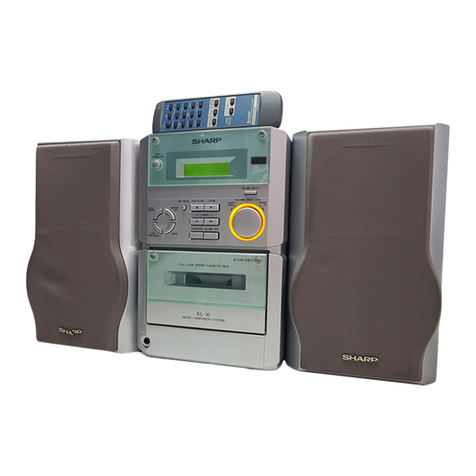
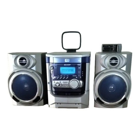
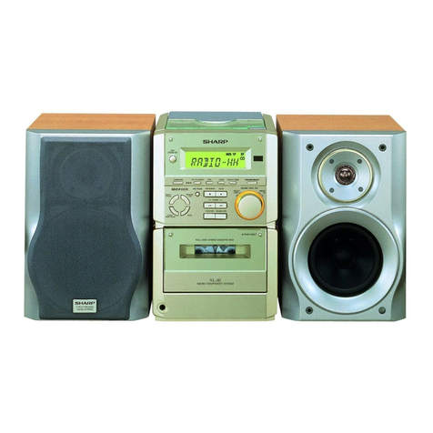
Sharp CD-BA2000H User manual

– 1 –
CD-BA2000H
No. S3020CDBA2000
CONTENTS Page
SAFETY PRECAUTION FOR SERVICE MANUAL ........................................................................................................... 2
IMPORTANT SERVICE NOTES (FOR U.K. ONLY) .......................................................................................................... 2
SPECIFICATIONS ............................................................................................................................................................. 3
NAMES OF PARTS ........................................................................................................................................................... 4
OPERATION MANUAL ..................................................................................................................................................... 6
QUICK GUIDE (FOR U.K. ONLY)...................................................................................................................................... 7
DISASSEMBLY.................................................................................................................................................................. 9
REMOVING AND REINSTALLING THE MAIN PARTS................................................................................................... 12
ADJUSTMENT ................................................................................................................................................................. 13
NOTES ON SCHEMATIC DIAGRAM .............................................................................................................................. 19
WAVEFORMS OF CD CIRCUIT...................................................................................................................................... 20
BLOCK DIAGRAM ........................................................................................................................................................... 21
SCHEMATIC DIAGRAM / WIRING SIDE OF P.W.BOARD..............................................................................................24
VOLTAGE ........................................................................................................................................................................ 42
TROUBLESHOOTING ..................................................................................................................................................... 43
FUNCTION TABLE OF IC................................................................................................................................................ 47
FL DISPLAY......................................................................................................................................................................53
WIRING OF PRIMARILY SUPPLY LEADS (FOR U.K. ONLY)........................................................................................ 54
REPLACEMENT PARTS LIST/EXPLODED VIEW
PACKING METHOD (FOR U.K. ONLY)
CD-BA2000H
• In the interests of user-safety the set should be restored to its
original condition and only parts identical to those specified be
used.
SERVICE MANUAL
This document has been published to be used
for after sales service only.
The contents are subject to change without notice.
SHARP CORPORATION
CD-BA2000H Mini Component System consisting of
CD-BA2000H(mainunit)andCP-BA2000H(speakersystem).
• Note for users in U.K.
Recording and playback of any material may require consent
which SHARP is unable to give. Please refer particularly to the
provisions of Copyright Act 1956, the Dramatic and Musical
Prefomers Protection Act 1956, the Preformers Protection Acts
1963 and 1972 and to any subsequent statutory enactments and
orders.

CD-BA2000H
– 2 –
SAFETY PRECAUTION FOR
SERVICE MANUAL
Precaution to be taken when replacing and servicing the
Laser Pickup.
The AEL (Accessible Emission Level) of Laser Power Output
forthismodelisspecifiedtobelowerthanClassIRequirements.
However, the following precautions must be observed during
servicing to protect your eyes against exposure to the Laser
beam.
(1) When the cabinet has been removed, the power is turned
on without a compact disc, and the Pickup is on a position
outerthanthelead-inposition,theLaserwilllightforseveral
seconds to detect a disc. Do not look into the Pickup Lens.
(2) The Laser Power Output of the Pickup inside the unit and
replacementservicepartshavealreadybeenadjustedprior
to shipping.
(3) No adjustment to the Laser Power should be attempted
when replacing or servicing the Pickup.
(4) Under no circumstances look directly into the Pickup Lens
at any time.
(5)CAUTION -Useofcontrolsoradjustments,orperformance
of procedures other than those specified herein may result
in hazardous radiation exposure.
IMPORTANT SERVICE NOTES (FOR U.K. ONLY)
Beforereturningtheunit to thecustomerafter completion ofa
repairoradjustmentitisnecessaryforthefollowingwithstand
voltage test to be applied to ensure the unit is safe for the
customer to use.
Setting of Withstanding Voltage Tester and set.
Set name set value
Withstanding Voltage Tester
Test voltage 4,240 VPEAK
3,000 VRMS
Set time 6 secs
Set current(Cutoff current) 4 mA
Unit
Judgment
OK: The “GOOD” lamp lights.
NG: The “NG” lamp lights and the buzzor sounds.
(For U.K.)
(Except for U.K.)
SHORT-CIRCUIT
AC POWER
SUPPLY CORD
CONNECT THE PROBE
TO GND OF CHASSIS
SCREW
PROBE
AC
UNIT
WITHSTANDING
VOLTAGE TESTER
+
-
OUT
Laser Diode Properties
Material: GaAIAs
Wavelength: 780 nm
Emission Duration: continuous
Laser Output: max. 0.6 mW
CAUTION-INVISIBLE LASER RADIATION WHEN OPEN. DO NOT STARE INTO
BEAM OR VIEW DIRECTLY WITH OPTICAL INSTRUMENTS.
VARNING-OSYNLIG LASERSTRALNING NAR DENNA DEL AR OPPNAD. STIRRA
EJ IN I STRALEN OCH BETRAKTA EJ STRALEN MED OPTISKA INSTRUMENT.
ADVERSEL-USYNLIG LASERSTRALING VED ABNING. SE IKKE IND I
STRALEN-HELLER IKKE MED OPTISKE INSTRUMENTER.
VARO! AVATTAESSA OLET ALTTIINA NAKYMATON LASERSATEILYLLE.
ALA TUIJOTA SATEESEEN ALAKA KATSO SITA OPTISEN LAITTEEN LAPI.
VARNING-OSYNLIG LASERSTRALNING NAR DENNA DEL AR OPPNAD.
STIRRA EJ IN I STRALEN OCH BETRAKTA EJ STRALEN GENOM OPTISKT
INSTRUMENT.
ADVERSEL-USYNLIG LASERSTRALING NAR DEKSEL APNES. STIRR IKKE
INN I STRALEN ELLER SE DIREKTE MED OPTISKE INSTRUMENTER.
VAROITUS! LAITTEEN KéYTTéMINEN MUULLA KUIN
TéSSé
KéYTTô OHJEESSA MAINITULLA TAVALLA SAATTAA
ALTISTAA KéYTTéJ éN TURVALLISUUSLUOKAN 1
YLITTéVéLLE NéKYMéTTôMéLLE LASERSéTEILYLLE.
VARNING - OM APPARATEN ANVéNDS Pè ANNAT SéTT
éN I DENNA BRUKSANVISNING SPECIFICERAS. KAN
ANVéNDAREN UTSéTTAS FôR OSYNLIG
LASERSTRèLNING, SOM ôVERSKRIDER GRéNSEN FôR
LASERKLASS 1.
LASER KLASSE 1
LUOKAN 1 LASERLAITE
KLASS 1 LASERAPPARAT
CHASSIS SCREW

– 3 –
CD-BA2000H
●General
Power source: AC 230 V, 50 Hz
Power consumption: 154 W
Dimensions: Width; 270 mm (10-5/8")
Height; 330 mm (13")
Depth; 355 mm (14")
Weight: 8.7 kg (19.2 lbs.)
●Amplifier section
Output power:
(For U.K.) RMS; 200 W (100 W + 100 W )
(10% T.H.D)
[Main speaker (woofer,
tweeter and super tweeter);
80 W (40 W + 40 W),
Subwoofer;
120 W (60 W + 60 W)]
RMS; 184 W (92 W + 92 W )
(0.9% T.H.D)
[Main speaker (woofer,
tweeter and super tweeter);
74 W (37 W + 37 W),
Subwoofer;
110 W (55 W + 55 W)]
Output terminals: Speakers; 6 ohms
Headphones; 16-50 ohms
(recommended; 32 ohms)
Input terminals: Video/Auxiliary (audio signal);
500 mV/47 kohms
●Compact disc player section
Type: 3-disc multi-play compact
disc player
Signal readout: Non-contact, 3-beam semi-
conductor laser pickup
D/A converter: 1-bit D/A converter
Frequency
response: 20 - 20,000 Hz
Dynamic range: 90 dB (1 kHz)
●Tuner section
Frequency range: FM; 87.5-108 MHz
AM; 522-1,620 kHz
●Cassette deck section
Frequency response: 50-14,000 Hz (Normal tape)
Signal/noise ratio: 55 dB (TAPE 1, playback)
50 dB (TAPE 2, recording/playback)
Wow and flutter:
(For U.K.) 0.3 % (WRMS)
●Speaker section
Type: 4-way type [13 cm (5-1/4") sub-
woofer, 13 cm (5-1/4") woofer,
5 cm (2") tweeter and super tweeter]
Maximum input power
(Total): 200 W
Rated input power
(Total): 100 W
Impedance: 6 ohms
Dimensions: Width; 270 mm (10-5/8")
Height; 330 mm (13")
Depth; 264.6 mm (10-3/8")
Weight: 4.7 kg (10.3 lbs.)/each
Output power:
(Except For U.K.) PMPO; 668 W
MPO; 334 W (167 W + 167 W )
(DIN 45 324)
[Main speaker (woofer, tweeter
and super tweeter);
134 W (67 W + 67 W),
Subwoofer;
200 W (100 W + 100 W)]
RMS; 200 W (100 W + 100 W )
(DIN 45 324)
[Main speaker (woofer, tweeter
and super tweeter);
80 W (40 W + 40 W),
Subwoofer;
120 W (60 W + 60 W)]
RMS; 184 W (92 W + 92 W )
(DIN 45 500)
[Main speaker (woofer, tweeter
and super tweeter);
74 W (37 W + 37 W),
Subwoofer;
110 W (55 W + 55 W)]
Wow and flutter:
(Except For U.K.) 0.35 % (DIN 45 511, playback)
Specifications for this model are subject to change without
prior notice.
SPECIFICATIONS
CD-BA2000H
CP-BA2000H
FOR A COMPLETE DESCRIPTION OF THE OPERATION OF THIS UNIT, PLEASE REFER
TO THE OPERATION MANUAL.

CD-BA2000H
– 4 –
NAMES OF PARTS
CD-BA2000H
1
678
25
2
4
5
14
10 12 13
19
22
18
33
9
11
24
23
20
21
1516 17
52
51
■Front panel
11.
(CD) Disc Tray
12.
Extra Bass Indicator
13.
Spectrum Analyzer/Volume Level Indicator
14.
(CD) Disc Number Indicators
15.
(CD/TUNER) Memory Indicator
16.
(TAPE 2) Record Indicator
17.
(CD) Play Indicator
18.
(CD) Music Schedule Indicators
19.
(CD) More Tracks Indicator
10.
(CD) Random Play Indicator
11.
(CD) Pause Indicator
12.
(TAPE) Play Indicator
13.
(CD) Repeat Indicator
14.
Dynamic PTY Indicator
15.
Programme Type Indicator
16.
Traffic Information Indicator
17.
EON Indicator
18.
Traffic Programme Indicator
19.
Sleep Indicator
20.
RDS Indicator
21.
FM Stereo Mode Indicator
22.
Traffic Announcement Indicator
23.
FM Stereo Indicator
24.
Timer Record Indicator
25.
Timer Play Indicator
26.
(TUNER) Programme Type/Traffic Information
Search Button
27.
(TUNER) EON Button
28.
(TUNER) ASPM Button
29.
(TUNER) Display Mode Selector Button
30.
(TUNER) Station Selector Button
31.
(CD) Track Up/Cue Button
3
(TUNER) Preset Up Button
3
(TAPE 2) Fast Forward Button
32.
Equalizer Mode Selector Button
33.
Timer Set Indicator
34.
On/Stand-by Button
35.
Timer/Sleep Button
36.
Clock Button
37.
Function Selector Buttons
38.
Headphone Socket
39.
Dimmer Button
40.
Volume Control
41.
(CD) Disc Number Select Buttons
42.
(CD) Open/Close Button
43.
Tuning and Time Up/Down Buttons
44.
Memory/Set Button
45.
(TAPE 2) Record Pause Button
46.
(CD) Track Down/Review Button
3
(TUNER) Preset Down Button
3
(TAPE 2) Rewind Button
47.
(CD/TAPE) Stop Button
48.
(CD) Play/Repeat Button
3
(TAPE) Play Button
49.
Extra Bass/Demo Mode Button
50.
(CD) Disc Skip Button
51.
(TAPE 1) Cassette Compartment
52.
(TAPE 2) Cassette Compartment
40
30
34
35
36
37
38
39
41
43 46 47 48 49 50
44 45
26 29 312827 32
33
42

– 5 –
CD-BA2000H
CP-BA2000H
■Rear panel
11.
AC Power Lead
12.
FM 75 Ohms Aerial Socket
13.
AM Loop Aerial Socket
14.
Speaker Terminals
15.
Video/Auxiliary (Audio Signal) Input Sockets
■Speaker
11.
Super Tweeter
12.
Tweeter
13.
Bass Reflex Duct
14.
Woofer
15.
Subwoofer
16.
Main Speaker (Woofer, Tweeter and Super Tweeter)
Wire
17.
Subwoofer Wire
3
1
2
4
5
1
2
36
4
7
5
■Remote control
11.
Remote Control Transmitter LED
●CD control section
12.
Disc Number Select Buttons
13.
Memory Button
14.
Pause Button
15.
Clear Button
16.
Track Down/Review Button
17.
Track Up/Cue Button
18.
Disc Skip Button
19.
Play/Repeat Button
10.
Stop Button
11.
Random Button
●Tuner control section
12.
Preset Up/Down Buttons
●Tape control section
13.
(TAPE 1) Play Button
14.
(TAPE 2) Record Pause Button
15.
(TAPE 1/2) Stop Button
16.
(TAPE 2) Play Button
17.
(TAPE 2) Rewind Button
18.
(TAPE 2) Fast Forward Button
●Common section
19.
Equalizer Mode Selector Button
20.
Function Selector Buttons
21.
On/Stand-by Button
22.
Extra Bass Button
23.
Volume Up/Down Buttons
1
2
3
4
5
6
7
8
9
10
11
12
13 14 15 16 17 18
19
20
21
22 23

CD-BA2000H
– 6 –
OPERATION MANUAL
(Continued)
Notes concerning use:
●Replace the batteries if the operating distance is reduced or if
the operation becomes erratic.
●Periodically clean the transmitter LED on the remote control
and the sensor on the main unit with a soft cloth.
●Exposing the sensor on the main unit to strong light may in-
terfere with operation. Change the lighting or the direction of
the unit.
●Keep the remote control away from moisture, excessive heat,
shock, and vibrations.
15
15
0.2 m - 6 m
(8" - 20')
SETTING THE CLOCK
ON/
STAND-BY
CLOCK
MEMORY/SET
TUNING/
TIME
( )
0:00 AM 0:00 AM 12:00
2
3
4
7
6
5
8
9
In this example, the clock is set for the 24-hour (0:00) system.
1
Press the ON/STAND-BY button to enter the stand-by mode.
2
Press the CLOCK button.
3
Within 5 seconds, press the MEMORY/SET button.
4
Press the TUNING/TIME ( or ) button to select the time
display mode.
"0:00" → The 24-hour display will appear.
(0:00 - 23:59)
"AM 0:00" → The 12-hour display will appear.
(AM 0:00 - PM 11:59)
"AM 12:00" →The 12-hour display will appear.
(AM 12:00 - PM 11:59)
●Note that this can only be set when the unit is first installed
or it has been reset (see page 29).
5
Press the MEMORY/SET button.
6
Press the TUNING/TIME ( or ) button to adjust the hour.
●Press the TUNING/TIME ( or ) button once to advance
the time by 1 hour. Hold it down to advance continuously.
●When the 12-hour display is selected, "AM" will change auto-
matically to "PM".
7
Press the MEMORY/SET button.
8
Press the TUNING/TIME ( or ) button to adjust the
minutes.
●Press the TUNING/TIME ( or ) button once to advance
the time by 1 minute. Hold it down to change the time in 5
minute intervals.
●The hour setting will not advance even if minutes advance from
"59" to "00".
9
Press the MEMORY/SET button.
●The clock starts operating from "0" second.
(Seconds are not displayed.)
And then the clock display will disappear after a few seconds.
To see the time display:
Press the CLOCK button.
●The time display will appear for about 5 seconds.
Note:
●The clock display will flash on and off at the push of the CLOCK
button when the AC power supply is restored after a power
failure occurs or after the AC power lead is disconnected.
If this happens, follow the procedure below to change the clock
time.
To change the clock time:
①
Press the CLOCK button.
②
Within 5 seconds, press the MEMORY/SET button.
③
Perform steps 6 - 9 above.
To change the time display mode:
①
Perform steps 1 - 2 in the section "RESETTING THE MICRO-
COMPUTER", on page 29.
②
Perform steps 1 - 9 above.
(Main unit operation)
X-BASS/
DEMO
ON/
STAND-BY
RESETTING THE MICROCOMPUTER
Reset the microcomputer under the following conditions:
●To erase all of the stored memory contents (clock and timer
settings, and tuner and CD presets).
●If the display is not correct.
●If the operation is not correct.
1
Press the ON/STAND-BY button to enter the stand-by mode.
2
Whilst pressing down the button and the X-BASS/DEMO
button, hold down the ON/STAND-BY button for at least 1
second.
●"CLEAR AL" will appear.
Caution:
●The operation explained above will erase all data stored in
memory including clock and timer settings, and tuner and CD
presets.

– 7 –
CD-BA2000H
Left speaker
Connections
4
AC 230 V, 50 Hz
1
Connect the AM and FM aerials.
2
Connect the speaker system.
3
Connect the AC power lead.
Blue
Red
Black
Right speaker
AM loop
aerial
FM aerial
1
2
Check the supplied accessories
AM loop aerial ×1
FM aerial ×1
Remote control ×1
Putting batteries into the remote control
Placing the system
10 cm (4")
10 cm (4") 10 cm (4")
10 cm (4")
●
2 "AA" size batteries
(UM/SUM-3, R6, HP-7 or similar)
●
Batteries are not included.
1
Remove the battery cover.
2
Insert the batteries.
3
Replacethe battery cover.
1
2
3

CD-BA2000H
– 8 –
7
Listening to a tape
1
Press the ON/STAND-BY button to turn the power on.
4
Press the TAPE (1 2) button to select the TAPE 1
or TAPE 2.
3
Load the cassette into the TAPE 1 or TAPE 2 cassette
compartment.
2
Open the cassette door by pushing the area marked
"PUSH EJECT".
5
Press the button to start playback.
1
Press the ON/STAND-BY button to turn the power on.
2
Press theTUNER (BAND) button to select FM ST, FM
or AM.
4
Rotate the VOLUME control to adjust the sound
volume.
6
Rotate the VOLUME control to adjust the sound
volume.
3
Press the TUNING/TIME ( or ) button to tune in-
to the desired station.
1
45
2
1
2
3
1
45
3,6
5
7
Listening to the radio
6
1
Press the ON/STAND-BY button to turn the power on.
2
Press the CD button.
3
PresstheOPEN/CLOSE buttonto open the disc tray.
4
Place the CD(s) on the disc tray, label side up.
5
When loading a third disc, press the DISC SKIP button
to turn the disc tray, then place the CD in the open pos-
ition.
6
Press the OPEN/CLOSE button to closethe disc tray.
Listening to a CD
5
8
TAPE 1 TAPE 2
PUSH
EJECT PUSH
EJECT
7
Press the button.
12 cm (5")
8 cm (3")
8
Rotate the VOLUME control to adjust the sound
volume.
2
3
3
4
6
2
●
And then, close the cassette door completely until it is locked.
●Resetting the microcomputer
1
Press the ON/STAND-BY button to enter the stand-by
mode.
2
Whilst pressing down the button and the X-BASS/
DEMO button, hold down the
ON/STAND-BY button for
at least 1 second.
●"CLEAR AL" will appear.
Caution:
●The operation explained above will erase all data stored
in memory including clock and timer settings, and tuner
and CD presets.
If this product is subjected to strong external interference
(mechanical shock, excessive static electricity, abnormal
supply voltage due to lightning, etc.) or if it is operated in-
correctly, it may malfunction or the display may not functi-
on correctly. If such a problem occurs, do the following:
●CD pickup cleaning
1
Press the ON/STAND-BY button to turn the power on.
2
Press the CD button and load the desired disc.
3
Load a cassette into the TAPE 2 cassette compartment.
4
Press the REC PAUSE button.
5
Press the button.
Recording from CDs
8
TAPE 2
PUSH
EJECT
3
22
1,2
5
4
1
2
Clean the dust or stain on the CD pickup lens
using a commercial cleaning disc (brush type).
Cleaning disc

– 9 –
CD-BA2000H
DISASSEMBLY
Caution on Disassembly
Follow the below-mentioned notes when disassembling
the unit and reassembling it, to keep it safe and ensure
excellent performance:
1. Take cassette tape and compact disc out of the unit.
2. Be sure to remove the power supply plug from the wall
outlet before starting to disassemble the unit.
3.Takeoffnylonbandsorwireholderswheretheyneedbe
removed when disassembling the unit. After servicing
theunit, be sure to rearrange the leads where theywere
before disassembling.
4. Take suffcient care on static electricity of integrated
circuits and other circuits when servicing.
Figure 9-2
Figure 9-3
CD-BA2000H
1 Top Cabinet 1. Screw ..................... (A1) x4 9-1
2 Side Panel 1. Screw ..................... (B1) x8 9-1
(Left/right)
3 CD Player Unit/ 1. Turn on the power supply, 9-2
CD Tray Cover open the disc tray, take out
the CD cover, and close.
(Note 1)
2. Screw ..................... (C1) x1
3. Hook....................... (C2) x3
4. Hook....................... (C3) x2
5. Socket .................... (C4) x2
4 Rear Panel 1. Screw ..................... (D1) x9 9-2
5 Main PWB 1. Screw ..................... (E1) x3 9-2
2. Socket .................... (E2) x3 10-2
3. Flat Cable............... (E3) x1
4. Tip Wire.................. (E4) x1
6
Power Supply PWB
1. Screw ..................... (F1) x2 10-2
2. Socket .................... (F2) x4
3. Flat Wire................. (F3) x1 10-3
7 Front Panel 1. Screw ..................... (G1) x2 10-2
8 Display PWB 1. Screw .....................
(H1) x14
10-3
2. Socket .................... (H2) x1
9 Tape Mechanism 1. Open the cassette holder. 10-3
2. Screw...................... (J1) x5
10
Headphones PWB
1. Screw ..................... (K1) x1 10-3
11 Turntable 1. Hook....................... (L1) x2 10-4
2. Cover ..................... (L2) x1
12 Disc Tray 1.
Turn fully the lock lever in the
9-3
arrow direction.
2.
While holding the lock lever,rotate
10-1
the cam gear until the cam gear
rib engages with the clamp lever.
3.
Push the slide holder backward to
10-5
engage the claw with the groove
and remove it in the direction
of the arrow. ..............
(M1) x6
13 CD Servo PWB 1. Screw ..................... (N1) x1 10-6
(Note 2) 2. Hook....................... (N2) x2
3. Socket .................... (N3) x4
14 CD Mechanism 1. Hook....................... (P1) x2 11-1
2. Hook....................... (P2) x3
15
Loading Motor PWB
1. Hook....................... (Q1) x5 11-1
STEP REMOVAL PROCEDURE FIGURE
Figure 9-1
CD-BA2000H
(B1)x4
ø3x10mm (B1)x2
ø3x10mm
Rear
Panel
(B1)x2
ø3x10mm
Side Panel
(Right)
Side Panel
(Left)
(A1)x2
ø3x12mm
(A1)x2
ø3x12mm Top Cabinet
(E1)x2
ø3x10mm
(E1)x1
ø3x6mm
(C3)x1
(D1)x2
ø3x10mm
(C1)x1
ø3x10mm
(D1)x7
ø3x10mm
CD Player
Unit
DC Tray Cover
Rear
Panel
Pull
(C3) x1
(C4)x2 (C2) x3
1
1
2
Main PWB
CD Servo
PWB
Note 1:
How to open the changer manually. (Fig. 9-3)
1. In this state, turn fully the lock lever in the arrow direction
through the hole on the loading chassis bottom.
2.
While holding the lock lever, rotate the cam gear anticlockwise
until the cam gear rib engages with the clamp lever.
(Fig. 10-1)
3. After that, push forward the CD slide holder.
Note 2:
1.Afterremoving the connectorfor the opticalpickupfrom the
connector, wrap the conductive aluminium foil around the
frontendoftheconnectorsoastoprotecttheopticalpickup
from electrostatic damage.
Note 3:
1. Be careful not to break the claw of the CD mechanism.
2.Whenfining back thecam gear assembly,let it lockby front
movement.
LOCK LEVER
CD-BA2000H
– 10 –
Figure 10-1
Figure 10-2
Figure 10-3
Figure 10-4
Figure 10-5
Figure 10-6
CLAMP LEVER
CAM GEAR RIB
(F1)x1
ø3x6mm
(G1)x2
ø3x10mm
(F1)x1
ø3x10mm
(F2)x3
(F2)x1
(E3)x1
(E4)x1
(E2)x2
Main PWB
(E2)x1
Power
Supply
PWB
Power
Supply
PWB
(H1)x14
ø3x10mm
(H2)x1
(J1)x5
ø3x10mm
(K1)x1
ø3x10mm
(F3)x1
Display PWB
Headphones
PWB
Open
Cassette
Holder
Tape
Mechanism
Turntable
Disc Tray
(L2) x1
CD Player Unit
(L1) x2
1
3
2
(M1) x3
(M1) x3
(N3) x2
(N2) x2
(N3) x2
CD Servo
PWB CD Player
Base
(N1)x1
ø3x8mm

– 11 –
CD-BA2000H
CP-BA2000H
1 Front Panel 1. Net.......................... (A1) x1 11-2
2. Rubber ................... (A2) x4
3. Screw ..................... (A3) x4
4. Tip .......................... (A4) x2 11-3
2 Woofer 1. Screw ..................... (B1) x4 11-3
3 Subwoofer 1. Screw .................... (C1) x4 11-3
4 Tweeter 1. Screw .................... (D1) x2 11-3
5 Super Tweeter 1. Screw .................... (E1) x2 11-3
STEP REMOVAL PROCEDURE FIGURE
Figure 11-2
(A1)x1
(A2)x4
(A3)x4
ø4x20mm
Screw
Driver
Driver should
be pried away
from Speaker
Box.
Front
Panel
(D1)x2
ø3x10mm
(C1)x4
ø4x16mm
(E1)x2
ø3x10mm
(B1)x4
ø4x16mm
(A4)x2
Super
Tweeter
Tweeter
Woofer
Subwoofer
Figure 11-3
Figure 11-1
(P2) x3
(P1) x1
(Q1) x5
(P1) x1
Loading
Motor
PWB
CD
Mechanism

CD-BA2000H
– 12 –
REMOVING AND REINSTALLING THE MAIN PARTS
TAPE MECHANISM SECTION
Perform steps 1 to 7 and 9 of the disassembly method to
remove the tape mechanism.
How to remove the record/playback and erase
heads (TAPE 2) (See Fig. 12-1)
1. When you remove the screw (A1) x 2 pcs., the recording/
playback head and three-dimensional head of the erasing
head can be removesd.
How to remove the playback head (TAPE 1)
(See Fig. 12-2)
1. When you remove the screw (B1) x 2 pcs., the playback
head.
How to remove the pinch roller (TAPE 1/2)
(See Fig. 12-3)
1.Carefully push the inside claw to remove it. Thepinch roller
pawlinthedirectionofthearrow<A>,andremovethepinch
roller (C1) upwards.
Note:
When installing the pinch roller, pay attention to the spring
mounting position.
How to remove the belt (TAPE 1) (See Fig. 12-4)
1. Remove the main belt (D1) x 1 pc., from the motor side.
2. Remove the FF/REW belt (D2) x 1 pc.
How to remove the belt (TAPE 2) (See Fig. 12-4)
1. Remove the main belt (E1) x 1 pc., from the motor side.
2. Remove the FF/REW belt (E2) x 1 pc.
How to remove the motor (See Fig. 12-5)
1. Remove the screws (F1) x 2 pcs., to remove the motor.
Figure 12-1
Figure 12-2
Figure 12-3
Figure 12-4Figure 12-5
TAPE2 TAPE1
Main Belt
(D1)x1
TAPE2
Main Belt
(E1)x1
TAPE1
Main Belt
FF/REW
Belt
(E2)x1
FF/REW
Belt
(D2)x1
Motor
Motor
(A1)x2
Ø2x9mm
TAPE2
Record/Playback
Head
Erase Head
(B1)x2
Ø2x9mm
TAPE1
Playback
Head
Pinch Roller
(C1)x1 <A>
STEP1
STEP2
(F1) x2
Ø2.6x5mm
Motor

– 13 –
CD-BA2000H
How to remove the pickup (See Fig. 13-2)
1. Remove the stop washer (B1) x 1 pc., to remove the gear
(B2).
2.Remove the screws (B3) x 2 pcs.,to remove the shaft (B4).
3. Remove the pickup.
Figure 13-2
CD MECHANISM SECTION
Perform steps 1, 2, 3, 11 and 14 of the disassembly method
to remove the CD mechanism.
How to remove the loading motor
(See Fig. 13-1)
1. Bend the hooks (A1) x 5 pcs., to remove the loading motor.
Figure 13-1
Note
After removing the connector for the optical pickup from the
connectorwraptheconductivealuminiumfoilaroundthefront
end of connector so as to protect the optical pickup from
electrostatic damage.
(A1)x2
(A1)x1
Loading Motor
CD Base
(A1)x2
(B3) x2
ø2.6 x6mm
Shaft
(B4) x1
Stop Washer
(B1) x1
Gear
(B2) x1
CD Mechanism
Pickup
ADJUSTMENT
MECHANISM SECTION
•Driving Force Check
Torque Meter Specified Value
Play: TW-2111 Tape 1: Over 80 g
Tape 2: Over 80 g
•Torque Check
Torque Meter
Tape 2
Play: TW-2111 30 to 80 g. cm 30 to 80 g.cm
Fast forward: TW-2231 — 70 to 180 g.cm
Rewind: TW-2231 — 70 to 180 g.cm
Specified Value
Tape 1
Specified
Value
Adjusting
Point Instrument
Connection
Test Tape
Normal MTT-111 Variable 3,000 ±Speaker
speed Resistor in 30 Hz terminal
motor. (Load
(MM1) resistance:
6 ohms)
•Tape Speed
Figure 13-3
TAPE MECHANISM
MM1
Motor
Variable Resistor in motor

CD-BA2000H
– 14 –
CD SECTION
• AM IF/RF
Signal generator: 400 Hz, 30%, AM modulated
*1. Input: Antenna, Output: TP302
*2. Input: Antenna, Output: TP301
TUNER SECTION
fL: Low-range frequency
fH: High-renge frequency
AM IF 450 kHz 1,720 kHz T351 *1
AM Band — 522 kHz (fL): T306 *2
Coverage 1.1 ±0.1 V
AM Tracking 990 kHz 990 kHz (fL): T303 *1
*1. Input: Antenna, Output: TP301
*2. Input: Antenna, Output: Speaker terminal
•FM RF
Signal generator: 1 kHz, 75 kHz dev., FM modulated
FM Band — 87.50 MHz
2.2 V ±50 mV*
1
Coverage
FM RF 98.00 MHz 98.00 MHz L312 *2
(10-30 dB)
Test Stage Instrument
Connection
Frequency Frequency
Display Serring/
Adjusting
Point
Figure 14-1 ADJUSTMENT POINT
Test Stage Frequency Frequency
Display Setting/
Adjusting
Parts
Instrument
Connection
FE301
R381
TP302
TP301
R357
AM IF
T303
T306
AM
TRACKING fL
AM BAND
COVERAGE fL
T351
TUNER PWB
CNP302
AM LOOP
ANTENNA
SO301
FM ANTENNA
1
Figure 14-2
CD ERROR CODE DESCRIPTION
Error State Code
[Servo System Error]
0001 Cannot detect Pickup-in SW
0002 DSP access error
[Error during close operation]
0101 Open/Close SW not functioning (Low →High)
0103 Open/Close SW not functioning (High →Low)
[Error during open operation]
0201 Open/Close SW not functioning (Low →High)
0203 Open/Close SW not functioning (High →Low)
[Error during skip operation]
0302 Pickup-in SW is not detected
0306 During Disc 1 search, Open/Close SW or Clamp SW
or Disc SW do not change to low.
0307 Clamp SW not function (Low →High)
0308 Clamp SW not function (High →Low)
Since this CD system incorporates the following automatic
adjustment functions, readjustment is not needed when
replacingthepickup.Therefore,differentPWBsandpickups
can be combined freely.
Each time a disc is changed, these adjustments are
performed automatically. Therefore, playback of each disc
can be performed under optimum conditions.
Items adjusted automatically
(1) Offset adjustment (The offset voltage between the head
amplifier output and the VREF reference voltage is
compensated inside the IC.)
* Focus offset adjustment
* Tracking offset adjustment
(2) Tracking balance adjustment (waveform drawing 14-2
EFBL)
(3)Gain adjustment (ThegainiscompensatedinsidetheIC
sothat theloop gain at the gain crossover frequency will
be 0dB.)
* Focus gain adjustment
* Tracking gain adjustment
•Adjustment
T
T
EFBL
FDO
TE
Stopped
CH1=500mV
DC 10:1 CH2=200mV
DC 10:1 CH3=1V
DC 10:1 500ms/div
(500ms/div)
NORM:20kS/s
1
2
3
=Record Length=
Smoothing : ON CH1 : 0.000V
CH2 : 0.000V Main : 100K
Zoom : 2k Mode : SINGLE
Type : EDGE CH1
Delay : 0.0ns
Hold off : 0.2us
CH3 : 0.00V
CH4 : 0.00V
BW : FULL
=Trigger==Filter= =Offset=
CH2
v/DIV
200mV
1999/04/05 20:26:47

– 15 –
CD-BA2000H
ASPM, summary operation
Yes Yes
Comparing freg.
same or not?
Between current receiving
frequency and (already)
previously memorized
frequency.
Hold down the ASPM button for 3 more second.
No operate. After displayed “END”. Return to
previous station.
“ASPM” blinks in the display.
Begin to scan start 87.50 →108.00 MHz
Preset CH memory full over?
SD (TUNE) DET out OK?
Yes
No
No
No
No
No
If count 1st OK?
Yes
If count 2nd OK?
Yes
RDS signal or not? PI—identify
Yes
Comparing PI cord
same or not?
between current receiving
PI and before PI which is
already memorized by
ASPM on this time.
Yes
Yes
No
Comparing freg.
same or not?
between current receiving
frequency and (already)
previouslymemorized
frequency.
No Memorized to the lowest vacant
preset channel.
No Memorized to the lowest vacant
preset channel.
Compare the field
strength of current receiving
signal.
Is receiving signal stronger than
signal which has same PI cord
and is already memorized to
preset memory ahead of this
receiving time?
No effect
No effect
No effect
Effect
Pass
No effect
Pass
No effect
Pass
No effect
Pass
No effect
Displayed the TTL quantity of memorized
stations by ASPM operation on this time.
And return to the previous
receiving freq. automatically.
Begin to ASPM SCAN from the next
CH-SPAN again.
Repeat and continue with same format
ASPM operation untill 108 MHz.
After reached 108 MHz, displayed the TTL
quantity of memorized stations.
And return to the previous receiving freq.
automatically.
Preset CH memory become full over?
Yes
No

CD-BA2000H
– 16 –
4. No adjust type (None adjusting circuit.)
5. Added EON button.
6. Need to change RDS logo due to the addition of EON feature.
7. Added EON—TI, EON—PTY function.
3. Summary of CD-BA2000H RDS—EON operation
EON—PTY: Select and set the desired “PTY” → stand-by → switch to ON (other network) Station at the start of desired PTY
automatically→stay and listen to PTY of ON station → switch back toTN (This net) station automatically at the end
of PTY (ON) i.e. after changing to another PTY (except AFFAIRS) or cancelling to receive PTY of ON station
midway.
EON—TI: Select and set the“TI” →stand-by →switch to ON station at the start of traffic announcement automatically →stay
and listen to TA of ON station → switch back to TN station automatically at the end of TA (ON).
ie after TA (ON) is over or cancelled to receive TA of ON station midway.
When switching TN → ON station.
In case of exist 2 more stations having the desired (specified) “PTY” or “TI”, the receiver will select and switch to ON station
comparing field strength at the same time. But when the frequency of ON station exists in the preset-memory, then receiver
switches straight to that ON station (CH), without comparing field strength so can make a quick switching fromTN—ON station.
Preset memory takes priority of switching TN—ON station.
Therefore ASPM is usefull not only for PTY search but also for rapid EON switching.
Anyway CD-BA2000H EON is basically stand-by and receiving method, along with the Guidelines for EON implementation.
• ASPM SCAN: 87.50MHz →108.00 MHz.
• Only RDS signal is memorized by ASPM because RDS signal has PI code and is suitable and convenient for ASPM operation.
ASPM
Comparing field strength, only one strongest RDS station is memorized of all stations (repeater relay stations) that have same
PI code.
Same PI code — freq: different
(AF’S)
PS: same
PTY: same
Each PI has AF’S list by individually.
Exa: P1 has f1, f2, f3(same PTY).
P2 has f4, f5(same PTY).
[For example] Pickup and memorized to preset CH.
f 1
f 2 f 3
P 1 (PI code)
PS 1 (Station Name)
f 5 f 4
P 2
PS 2
f 6
f 7 f 8
P 3
PS 3
f 9 f 10
f 11 f 12 f13
P 4
PS 4
Select signals (f1, f5, f7, f10) are memorized in the preset memory by ASPM.
• If tentative - ASPM operation is repeated intentionally, never memorized (over write) at the same frequecy.
1st time ASPM → strongest stations of each PI are memorized.
ASPM is not only very usefull for PTY search, but also EON operation.
2nd time ASPM →2nd strong stations of each PI are memorized and so on.
PTY search function is equal to FM band search function as a result.
1. Introduction of RDS for CD-BA2000H
CD-BA2000H RDS function is equal to adding EON feature to the current CD-C75H RDS.
EON feature is EON—PTY and EON—TI.
Although PTY and TI indicators are separated, PTY containsTI in the PTY items (software) like current PTY search items.
NEWS, AFFAIRS, INFO, ALARM, TI (TTL 17 kinds)
EON—PTY EON—TI
Can select and stand-by Can select and stand-by
EON—PTY and EON—TI are basically stand-by →receive the desired program of ON station.
2.The difference point from current CD-C75H RDS. (CD-C75H — CD-BA2000H)
1.PTY item: added TA. (TTL 18 kind.)
2.Each “TP”, “TA” ind. light up or go out individually.
“TA” ind.doesn’t light up on current model, CD-C75H due to none EON—TI.
3.Added 3 indicators(in FL) due to adding EON feature.
EON: Lights up only during receiving EON data (14A).
TI: During EON-TI stand-by →Light up
During receiving ON station. →blink.
PTY: During EON-PTY stand-by →Light up
During receiving ON station. →blink.
---
---
↑↑

– 17 –
CD-BA2000H
EON summary notice for reference
1. EON-TI/PTY EON stand-by can be set, only when EON ind. lights up.
While EON ind. goes out (NO EON STATION), EON stand-by can't be set.
If the EON button is pressed, then “NO EON” is indication the display.
2. EON-TI/PTY Even if switch back ON → TN station continue to keep EON stand-by.
3. EON-TI Don’t switch TN → ON during TN broadcast TA. (same item)
4. EON-TI/PTY
EONcanbecancelledduringreceivingONstationbypressingEONbuttonifnecessaryandswitchbackON
→
TN.
5. EON-TI/PTY EONstand-byisperfectlycancelled(cleared)bypressingEONbutton2timesduringstand-byorpowerOFF
or Tun Up/Down or change band or recall pre-set CH.
6. EON-TI/PTY After setting EON stand-by, stand-by items can be confirmed by pressing EON button one time.
7. EON-TI/PTY EON button function: • EON setting
• Confirm stand-by items
• Cancel (ON→TN)
• EON clear cancel (2 times)
8. EON-TI/PTY After setting EON-TI and EON-PTY stand-by, if when EON data is not transmitted, EON ind goes out and
EON stand-by is automatically cancelled display “NO EON”.
9. EON-TI EON-TI stand-by can't be set. When TP=0,TA=0 (TN) even if EON ind. lights up and the EON button is
pressed then “NO TI” is indication the display.
10. EON-PTY Don’t switch TN → ON during TN broadcast same specified PTY. (same item of PTY)
11. EON-TI/PTY Switch TN→ON →TN station one cycle.
Never switch TN → ON1 → ON2 →Other net to other net station.
12. EON-TI/PTY After switch TN → ON station. When ON station is NO RDS, NO signal, TA=OFF or different PTY items.
The receiver switch back ON → TN displaying “NO READY”.
13. During receive ON station. when ON station become to be NO RDS, NO signal, TA=ON to OFF or different
PTY item, The receiver switch back ON → TN.
14. EON-TI/PTY SwitchTN→ONincaseof2morestationsexist,comparingfieldstrengthandswitchtothestrongeststation,
if these signals are same strength, switch to the first previous station.
Ifsame frequency asAF'Sexists in thepreset memory, thenswitch TN → ON (presetmemory station) straight.
In case of exist 2 more preset memories of AF’S,then switch to the preset CH which taken in EON DATA
first, also in this case no concern to field strength.
15. Even if switch TN → ON preset memory straight, that ON station is very weak signal, then search another
AF'S (ON) station comparing field strength and switch to the strongest station as a result. Of all atations of
AF'S are very weak or no good condition, then, switch back ON → TN automatically display "NO READY".
16. EON-TI/PTY No linkage volume, power ON/OFF, and switch function.
Traffic Programme code
(TP) Traffic Announcement code
(TA) Applications
OFF OFF This programme does not carry traffic announcements nor does
it refer, via EON, to a programme that does.
OFF ON This programmecarries EON information about another
programme which gives traffic information.
ON OFF This programme carries traffic announcements but none are
being broadcast at present and may also carry EON information
about other traffic announcements.
ON ON A traffic announcement is being broadcast on this programme
at present.

CD-BA2000H
– 18 –
RDS (Radio Data System) OPERATION
RDS is a broadcasting service which a growing number
of FM stations are now providing. It allows these FM
stations to send additional signals along with their regu-
lar programme signals. For example, the stations send
their station names, and information about what type of
programme they broadcast, such as sports or music,
etc.
When tuned to an FM station which provide the RDS
service, the RDS will appear, the station frequency (and
then the station name if sent) is displayed.
The TP (Traffic Programme) will appear on the display
when the received broadcast carries traffic an-
nouncements, and the TA (Traffic Announcement) will
appear whilst a traffic announcement is being received.
EON will appear whilst the EON (Enhanced Other Net-
works information) data is being broadcast.
The PTYI (Dynamic PTY Indicator) will appear whilst the
Dynamic PTY station is being received.
Note:
When the TP and TA appear at the same time, an an-
nouncement is being made.
When only the TA appears, an announcement is not
being made. (See page 24.)
■
Information Provided by RDS
With the CD-BA2000H, you can display three types of RDS ser-
vice. To show them in the display, press the DISPLAY MODE
button.
Each time you press the DISPLAY MODE button, the display will
change to show the following information.
PS (Programme Service): Station names commonly
known will be displayed.
"NO PS" appears if no signal
is being received.
PTY (Programme Type): Programme type will be dis-
played.
"NO PTY" appears if no sig-
nal is being received.
RT (Radio Text): Radio text will be displayed.
"NO RT" appears if no signal
is being received.
Station Frequency: Station frequencies.
DISPLAY
MODE
(Continued)
Descriptions of the PTY (Programme Type) codes, TP (Traffic Programme) and TA (Traffic Announcement)
With the CD-BA2000H, you can search for and receive the following PTY, TP and TA signals.
NEWS:
Short accounts of facts, events and
publicly expressed views, reportage
and actuality.
AFFAIRS:
Topical programme expanding or en-
larging upon the news, generally in dif-
ferent presentation style or concept,
including debate, or analysis.
INFO:
Programmes whose purpose is to im-
part advice in the widest sense.
SPORT:
Programme concerned with any aspect
of sport.
EDUCATE:
Programme intended primarily to edu-
cate, of which the formal element is
fundamental.
DRAMA:
All radio plays and serials.
CULTURE:
Programmes concerned with any as-
pect of national or regional culture, in-
cluding language, theatre, etc.
SCIENCE:
Programmes about the natural scien-
ces and technology.
VARIED:
Used for mainly speech-based pro-
grammes usually of light-entertainment
nature, not covered by other ca-
tegories. Examples include: quizzes.
panel games, personality interviews.
POP M:
Commercial music, which would gener-
ally be considered to be of current
popular appeal, often featuring in cur-
rent or recent record sales charts.
ROCK M:
Contemporary modern music, usually
written and performed by young musi-
cians.
EASY M:
Current contemporary music con-
sidered to be "easy-listening", as op-
posed to Pop, Rock or Classical, or one
of the specialized music styles, Jazz,
Folk or Country. Music in this category
is often but not always, vocal, and
usually of short duration.
LIGHT M:
Classical Musical for general, rather
than specialist appreciation. Examples
of music in this category are instrumen-
tal music, and vocal or choral works.
CLASSICS:
Performances of major orchestral
works, symphonies, chamber music
etc., and including Grand Opera.
OTHER M:
Musical styles not fitting into any of the
other categories. Particularly used for
specialist music of which Rhythm &
Blues and Reggae are examples.
WEATHER:
Weather reports and forecasts and Me-
teorological information.
FINANCE:
Stock Market reports, commerce, trading etc.
CHILDREN:
For programmes targeted at a young audience,
primarily for entertainment and interest, rather
than where the objective is to educate.
SOCIAL:
Programmes about people and things that in-
fluence them individually or in groups. Includes:
sociology, history, geography, psychology and
society.
RELIGION:
Any aspect of beliefs and faiths, involving a God
or Gods, the nature of existence and ethics.
PHONE IN:
Involving members of the public expressing their
views either by phone or at a public forum.
TRAVEL:
Features and programmes concerned with travel
to near and far destinations, package tours and
travel ideas and opportunities. Not for use for
Announcements about problems, delays, or
roadworks affecting immediate travel where
TP/TA should be used.
LEISURE:
Programmes concerned with recreational acti-
vities in which the listener might participate.
Examples include, Gardening, Fishing. Antique
collecting, Cooking, Food & Wine etc.
JAZZ:
Polyphonic, syncopated music characterised by
improvisation.
COUNTRY:
Songs which originate from, or continue the mu-
sical tradition of the American Southern States.
Characterised by a straightforward melody and
narrative story line.
NATION M:
Current Popular Music of the Nation or Region
in that country's language, as opposed to Inter-
national `Pop' which is usually US or UK inspired
and in English.
OLDIES:
Music from the so-called "golden age" of popular
music.
FOLK M:
Music which has its roots in the musical culture
of a particular nation, usually played on acoustic
instruments. The narrative or story may be
based on historical events or people.
DOCUMENT:
Programme concerned with factual matters,
presented in an investigative style.
TEST:
Broadcast when testing emergency broadcast
equipment or receivers.
ALARM !:
Emergency announcement made under excep-
tional circumstances to give warning of events
causing danger of a general nature.
NONE:
No programme type (receive only).
TP:
Broadcasts which carry traffic announcements.
TA:
Traffic announcements are being broadcast at
present.
Note:
●When the unit is in the EON stand-by mode and a programme
is selected, the unit will display "TI" instead of "TA".

– 19 –
CD-BA2000H
•The indicated voltage in each section is the one measured
by Digital Multimeter between such a section and the chas-
sis with no signal given.
1. In the tuner section,
( ) indicates AM
< > indicates FM stereo
2. In the main section, a tape is being played back.
3. In the deck section, a tape is being played back.
( ) indicates the record state.
4. In the power section, a tape is being played back.
5. In the CD section, the CD is stopped.
•Parts marked with “ ” ( ) are important for
maintaining the safety of the set. Be sure to replace these
parts with specified ones for maintaining the safety and
performance of the set.
NOTES ON SCHEMATIC DIAGRAM
•Resistor:
To differentiate the units of resistors, such symbol as K and
M are used: the symbol K means 1000 ohm and the symbol
M means 1000 kohm and the resistor without any symbol is
ohm-type resistor. Besides, the one with “Fusible” is a fuse
type.
•Capacitor:
To indicate the unit of capacitor, a symbol P is used: this
symbol P means micro-micro-farad and the unit of the
capacitor without such a symbol is microfarad. As to
electrolyticcapacitor,theexpression“capacitance/withstand
voltage” is used.
(CH), (TH), (RH), (UJ): Temperature compensation
(ML): Mylar type
(P.P.): Polypropylene type
•Schematic diagram and Wiring Side of P.W.Board for this
model are subject to change for improvement without prior
notice.
REF. NO DESCRIPTION POSITION POSITION
SW713 OPEN/CLOSE ON—OFF
SW714 DIMMER ON—OFF
SW715 X-BASS/MEMO ON—OFF
SW716 EQALIZER ON—OFF
SW722 CD ON—OFF
SW723 TAPE ON—OFF
SW724 TUNING/TIME DOWN ON—OFF
SW725 MEMORY/SET ON—OFF
SW726 PRESET DOWN ON—OFF
SW727 PRESET UP ON—OFF
SW728 PLAY/REPEAT ON—OFF
SW729 STOP ON—OFF
SW731 REC/PAUSE ON—OFF
SW732 TUNING/TIME UP ON—OFF
SW733 VIDEO/AUX ON—OFF
SW734 TUNER (BAND) ON—OFF
REF. NO DESCRIPTION
SW1 OPEN/CLOSE ON—OFF
SW2 CLAMP ON—OFF
SW3 DISC NUMBER ON—OFF
SW4 PICKUP IN ON—OFF
SW701 POWER ON—OFF
SW702 CLOCK ON—OFF
SW703 TIMER/SLEEP ON—OFF
SW704 STAION ON—OFF
SW705 EON ON—OFF
SW706 ASPM ON—OFF
SW707 DISPLAY MODE ON—OFF
SW708 STAION ON—OFF
SW709 DISC 1 ON—OFF
SW710 DISC 2 ON—OFF
SW711 DISC 3 ON—OFF
SW712 DISC SKIP ON—OFF
Figure 19 TYPES OF TRANSISTOR AND LED
(1) (2) (3)
(S) (G) (D)
E C B
FRONT
VIEW
2SC380 O
2SA1015 GR
2SC1845 F
KTC3203 Y
KTA1266 GR
KRC102 M
KRC104 M
KTA1271 Y
KTA1273 Y
KTA1274 Y
KTC2026
KTC3199 GR
4204UYT7
4204SRT7
FRONT
VIEW

CD-BA2000H
– 20 –
WAVEFORMS OF CD CIRCUIT
T
FDO
TDO
Stopped
CH1=500mV
DC 10:1 CH3=500mV
DC 10:1 500ms/div
(500ms/div)
NORM:20kS/s
1
3
=Record Length=
Smoothing : ON CH1 : 0.000V
CH2 : 0.0V Main : 100K
Zoom : 2K Mode : AUTO
Type : EDGE CH1
Delay : 0.0ns
Hold off : 0.2us
CH3 : 0.000V
CH4 : 0.00V
BW : FULL
=Trigger==Filter= =Offset=
CH1
v/DIV
500mV
1IC2 24
2IC2 23
T
FDO
DRF
TE
Stopped
CH1=500mV
DC 10:1 CH2=10V
DC 10:1 CH3=1V
DC 10:1 500ms/div
(500ms/div)
NORM:20kS/s
1
2
3
=Record Length=
Smoothing : ON CH1 : 0.000V
CH2 : 0.0V Main : 100K
Zoom : 2K Mode : AUTO
Type : EDGE CH1
Delay : 0.0ns
Hold off : 0.2us
CH3 : 0.00V
CH4 : 0.00V
BW : FULL
=Trigger==Filter= =Offset=
-3div -1div 0div +1div +3div
CH Position To
CH2
Position
0.20div
1
IC2 24
3
IC2 72
4
IC1 18 ,
IC2 16
Vp-p=1.0V~1.3V
0.5mV/div,0.5µsec/div
5
IC1 27
T
T
TE
DRF
Stopped
CH1=10V
DC 10:1 CH2=1V
DC 10:1 100ms/div
(100ms/div)
NORM:100kS/s
2
1
=Record Length=
Smoothing : ON CH1 : 0.0V
CH2 : 0.00V Main : 100K
Zoom : 2K Mode : NORMAL
Type : EDGE CH1
Delay : 2.924ms
Hold off : 0.2us
CH3 : 0.00V
CH4 : 0.00V
BW : FULL
=Trigger=
=Filter= =Offset=
3
IC2 72
4
IC1 18 ,
IC2 16
T
T
FDO
SPDO
Stopped
CH1=200mV
DC 10:1 CH2=500mV
DC 10:1 500ms/div
1999/04/07 09:51:15
(500ms/div)
NORM:20kS/s
2
1
=Record Length=
Smoothing : ON CH1 : 0.000V
CH2 : 0.000V Main : 100K
Zoom : 2K Mode : NORMAL
Type : EDGE CH2
Delay : 2.924ms
Hold off : 0.2us
CH3 : 0.00V
CH4 : 0.00V
BW : FULL
=Trigger=
=Filter= =Offset=
1
IC2 24
6
IC2 25
T
FDO
PDO2
PDO1
Stopped
CH1=500mV
DC 10:1 CH3=1V
DC 10:1 CH4=1V
DC 10:1 500ms/div
(500ms/div)
NORM:20kS/s
1
4
3
=Record Length=
Smoothing : ON CH1 : 0.000V
CH2 : 0.0V Main : 100K
Zoom : 2K Mode : AUTO
Type : EDGE CH2
Delay : 0.0ns
Hold off : 0.2us
CH3 : 0.00V
CH4 : 0.00V
BW : FULL
=Trigger==Filter= =Offset=
CH1
v/DIV
500mV
1999/04/05 17:33:17
1
IC2 24
7
IC2 1
8
IC2 2
T
T
DOUT
Stopped
CH1=2V
DC 10:1 500ns/div
1999/04/07 09:25:28
(500ns/div)
NORM:200MS/s
1
=Record Length=
Smoothing : ON CH1 : 0.00V
CH2 : 0.00V Main : 1K
Zoom : 100 Mode : NORMAL
Type : EDGE CH1
Delay : 2.887ms
Hold off : 0.2us
CH3 : 0.00V
CH4 : 0.00V
BW : FULL
=Trigger=
=Filter= =Offset=
9IC2 37
T
T
DATA
DATACK
LRSY
Stopped
CH1=2V
DC 10:1 CH2=2V
DC 10:1 CH3=2V
DC 10:1 5us/div
(5us/div)
NORM:100kS/s
1
2
3
=Record Length=
Smoothing : ON CH1 : 0.00V
CH2 : 0.00V Main : 5K
Zoom : 100 Mode : AUTO
Type : EDGE CH3
Delay : 0.0ns
Hold off : 0.2us
CH3 : 0.00V
CH4 : 0.00V
BW : FULL
=Trigger==Filter= =Offset=
CH3
v/DIV
2 V
1999/04/05 20:50:17
10
IC2 57
IC2 58
IC2 59
11
12
T
T
EFBL
FDO
TE
Stopped
CH1=500mV
DC 10:1 CH2=200mV
DC 10:1 CH3=1V
DC 10:1 500ms/div
(500ms/div)
NORM:20kS/s
1
2
3
=Record Length=
Smoothing : ON CH1 : 0.000V
CH2 : 0.000V Main : 100K
Zoom : 2k Mode : SINGLE
Type : EDGE CH1
Delay : 0.0ns
Hold off : 0.2us
CH3 : 0.00V
CH4 : 0.00V
BW : FULL
=Trigger==Filter= =Offset=
CH2
v/DIV
200mV
1999/04/05 20:26:47
1
IC2 24
4
IC1 18 ,
IC2 16
IC1 13 ,
IC2 22
13
Other manuals for CD-BA2000H
1
Table of contents
Other Sharp Stereo System manuals

Sharp
Sharp CD-ES111H User manual

Sharp
Sharp CD-MPS600 User manual

Sharp
Sharp CD-ES600 User manual

Sharp
Sharp CD-BA3100 User manual

Sharp
Sharp CP-DP900S User manual

Sharp
Sharp XL-530H User manual

Sharp
Sharp AQUOS CD-BA250 User manual

Sharp
Sharp XL-T300H User manual

Sharp
Sharp CD-BA120 User manual

Sharp
Sharp CD-G10000V User manual

Sharp
Sharp CD-XP700 User manual

Sharp
Sharp XL-UH06H User manual

Sharp
Sharp SD-NX10W User manual

Sharp
Sharp XL-UH3H User manual

Sharp
Sharp QT-V5E User manual

Sharp
Sharp XL-3000W User manual

Sharp
Sharp CD-E700 User manual

Sharp
Sharp QT-CD110H User manual

Sharp
Sharp CD-XP120 User manual

Sharp
Sharp XL-DK227NH User manual