Sharp XL-G5000DVD User manual

XL-G5000DVD/XL-G5000DVD(S)
SERVICE MANUAL
No. XXXXXXXXXXXXX
DVD MICRO SYSTEM
XL-G5000DVD
XL-G5000DVD(S)
MODEL
SHARP CORPORATION This document has been published to be used
for after sales service only.
The contents are subject to change without notice.
CHAPTER 1. GENERAL DESCRIPTION
[1] SPECIFICATIONS.........................................1-1
[2] NAMES OF PARTS.......................................1-2
CHAPTER 2. ADJUSTMENTS
[1] ADJUSTMENT...............................................2-1
[2] TEST MODE .................................................2-3
[3] Standard Specification of Stereo System
Error Message Display Contents..................2-10
CHAPTER 3. MECHANICAL DESCRIPTION
[1] REMOVING AND REINSTALLING THE
MAIN PARTS..................................................3-1
[2] DISASSEMBLY..............................................3-3
CHAPTER 4. DIAGRAMS
[1] BLOCK DIAGRAM .........................................4-1
CHAPTER 5. CIRCUIT DESCRIPTION
[1] WAVEFORMS OF DVD CIRCUIT..................5-1
[2] VOLTAGE.......................................................5-2
CHAPTER 6. CIRCUIT SCHEMATICS AND PARTS
LAYOUT
[1] NOTES ON SCHEMATIC DIAGRAM............6-1
[2] TYPES OF TRANSISTOR AND LED............6-1
[3] WIRING SIDE OF PWB/SCHEMATIC
DIAGRAM......................................................6-2
CHAPTER 7. FLOWCHART
[1] TROUBLESHOOTING ..................................7-1
CHAPTER 8. OTHERS
[1] FUNCTION TABLE OF IC.............................8-1
[2] FL DISPLAY ..................................................8-8
CHAPTER 9. ACTIVE SUBWOOFER DIAGRAM
[1] BLOCK DIAGRAM ........................................9-1
[2] WIRING SIDE OF PWB/SCHEMATIC
DIAGRAM......................................................9-3
Parts Guide
XL-G5000DVD DVD Micro System consisting of XL-G5000DVD
(Main Unit) and CP-G5000 (Front Speaker).
XL-G5000DVD(S) DVD Micro System consisting of XL-G5000DVD(S)
(Main Unit) and CP-G5000(S) (Front Speaker).
•
In the interests of user-safety the set should be restored to its original
condition and only parts identical to those specified be used.
XL-G5000DVD(S) is silver color of XL-G5000DVD
XL-G5000DVD
and
XL-G5000DVD(S)
NTSC/PAL
SPEAKER SYSTEM
CP-G5000
CP-G5000(S)
MODEL
CP-G5000 Speaker System consisting of CP-SW5000 (Active
Subwoofer) and GBOXSA052AWM1 (Surround Speaker).
CP-G5000(S) Speaker System consisting of CP-SW5000(S) (Active
Subwoofer) and GBOXSA066AWM1 (Surround Speaker).
CONTENTS

XL-G5000DVD/XL-G5000DVD(S)
– i –
SAFETY PRECAUTION FOR SERVICE MANUAL
Precaution to be taken when replacing and servicing the Laser Pickup.
The AEL (Accessible Emission Level) of Laser Power Output for this model is specified to be lower than Class 1 Requirements.
However, the following precautions must be observed during servicing to protect your eyes against exposure to the Laser beam.
1. When the cabinet has been removed, the power is turned on without a compact disc, and the Pickup is on a position outer than the
lead-in position, the Laser will light for several seconds to detect a disc. Do not look into the Pickup Lens.
2. The Laser Power Output of the Pickup inside the unit and replacement service parts have already been adjusted prior to shipping.
3. No adjustment to the Laser Power should be attempted when replacing or servicing the Pickup.
4. Under no circumstances look directly into the Pickup Lens at any time.
5. CAUTION - Use of controls or adjustments, or performance of procedures other than those specified herein may result in
hazardous radiation exposure.
VOLTAGE SELECTION
Before operating the unit on mains, check the preset voltage. If the voltage is different from your local voltage, adjust the voltage
as follows.
Turn the selector with a screwdriver until the appropriate voltage number appears in the window (110V,127V,220V or 230V -
240V AC).
AC POWER SUPPLY CORD AND AC PLUG ADAPTOR
QACCE0015AW00
QACCA0008AW00
QPLGA0003AWZZ QPLGA0004AWZZ

XL-G5000DVD/XL-G5000DVD(S)
– ii –
AudioXL-HP404VService ManualXLHP404VMarketE
PRECAUTIONS FOR USING LEAD-FREE SOLDER
1. Employing lead-free solder
"VCD PWB" of this model employs lead-free solder. The LF symbol indicates lead-free solder, and is attached on the PWB and
service manuals. The alphabetical character following LF shows the type of lead-free solder.
Example:
Indicates lead-free solder of tin, silver and copper.
2. Using lead-free wire solder
When fixing the PWB soldered with the lead-free solder, apply lead-free wire solder. Repairing with conventional lead wire solder
may cause damage or accident due to cracks.
As the melting point of lead-free solder (Sn-Ag-Cu) is higher than the lead wire solder by 40 C, we recommend you to use a
dedicated soldering bit, if you are not familiar with how to obtain lead-free wire solder or soldering bit, contact our service station
or service branch in your area.
3. Soldering
As the melting point of lead-free solder (Sn-Ag-Cu) is about 220 C which is higher than the conventional lead solder by 40 C,
and as it has poor solder wettability, you may be apt to keep the soldering bit in contact with the PWB for extended period of
time. However, Since the land may be peeled off or the maximum heat-resistance temperature of parts may be exceeded,
remove the bit from the PWB as soon as you confirm the steady soldering condition.
Lead-free solder contains more tin, and the end of the soldering bit may be easily corrected. Make sure to turn on and off the
power of the bit as required.
If a different type of solder stays on the tip of the soldering bit, it is alloyed with lead-free solder. Clean the bit after every use
of it.
When the tip of the soldering bit is blackened during use, file it with steel wool or fine sandpaper.
Be careful when replacing parts with polarity indication on the PWB silk.
Lead-free wire solder for servicing
Ref No. DescriptionParts No.
PWB-D 92LPWB5619VCDS VCD

XL-G5000DVD/XL-G5000DVD(S)
1 – 1
AudioXL-DV555WService ManualXLDV555WMarketE
CHAPTER 1. GENERAL DESCRIPTION
[1] SPECIFICATIONS
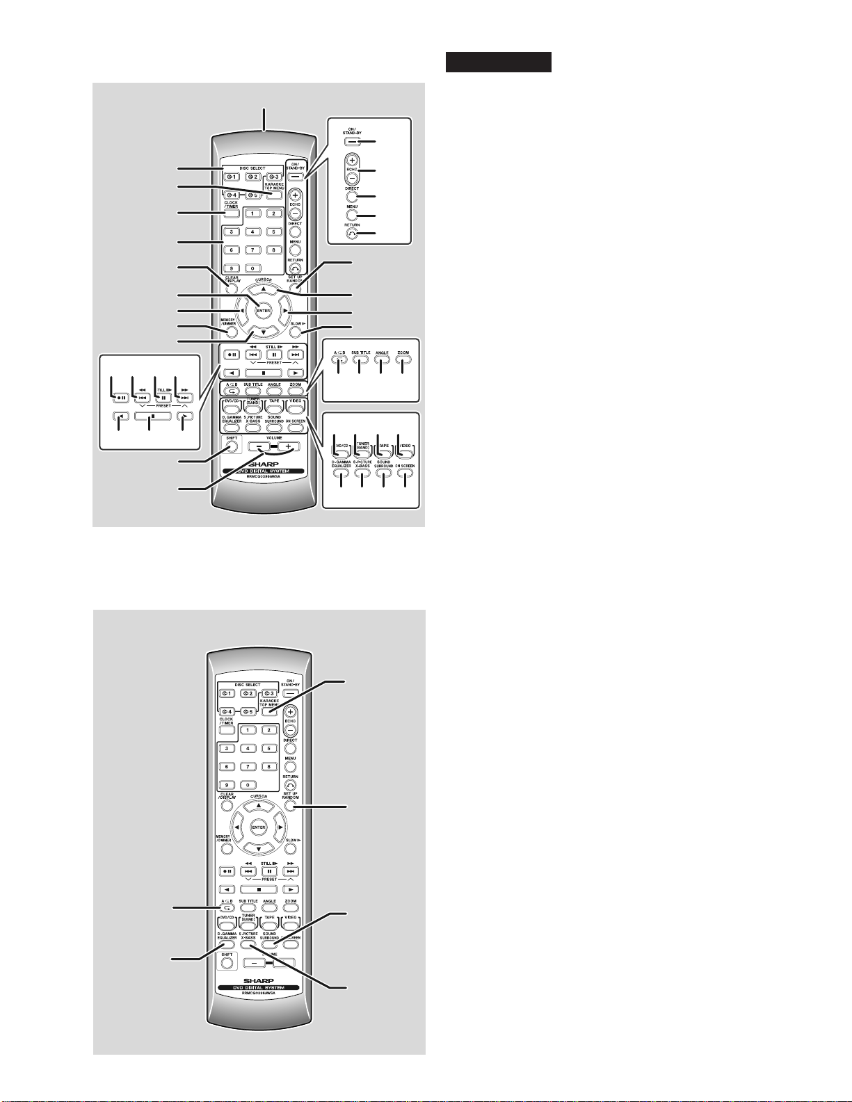
FOR A COMPLETE DESCRIPTION OF THE OPERATION OF THIS UNIT, PLEASE REFER
TO THE OPERATION MANUAL
■
Cassette deck
Frequency response 50 - 14,000 Hz (normal tape)
Signal/noise ratio 50 dB (recording/playback)
Wow and flutter 0.3 % (WRMS)
■
DVD/VCD/CD player
Signal system NTSC/PAL
Supported disc types DVD, audio CD, CD-R, CD-RW, VCD, MP3/
WMA
Video output Output socket: Pin socket x 1
Output level: 1 Vp-p (75 ohms)
S-video output Y output level: 1 Vp-p (75 ohms)
C output level: 0.628 Vp-p (75 ohms)
Output socket: S-video connector x 1
Video signal Horizontal resolution: 500 lines
S/N ratio: 60 dB
Audio signal Frequency characteristics:
Linear PCM DVD:
4 Hz to 22 kHz (48 kHz sampling)
4 Hz to 44 kHz (96 kHz sampling)
CD: 4 Hz to 20 kHz
S/N ratio: 96 dB, 1 kHz (CD)
Dynamic range:
96 dB (Linear PCM DVD)
96 dB (CD)
Total harmonic distortion ratio:
0.006 % maximum
■
Tuner
Frequency range FM: 88.0 - 108.0 MHz
AM: 531 - 1,602 kHz
Type 2-way type speaker system
5 cm (2") tweeter
13 cm (5-1/8") woofer
Maximum input power
130 W
Rated input power 65 W
Impedance 8 ohms
Dimensions
Weight 3.0 kg (6.6 lbs.)/each
■
General
XL-G5000DVD
CP-G5000 (Front Speaker)
GBOXSA052AWM1 (Surround Speaker)
CP-SW5000 (Subwoofer)
Power source AC 110/127/220/230 - 240 V, 50/60Hz
Power consumption 90 W
Dimensions Width : 185 mm (7-1/4")
Height : 260 mm (10-1/4")
Depth : 307 mm (12")
Width : 165 mm (6-1/2")
Height : 260 mm (10-1/4")
Depth : 231mm (9-15/16")
Type
Maximum input power
70 W
Rated input power 35 W
Impedance 16 ohms
Dimensions
Weight 2.5 kg (5.5 lbs.)/each
Width : 120 mm (4-3/4")
Height : 260 mm (10-1/4")
Depth : 227mm (8-15/16")
Width : 320 mm (12-5/8")
Height : 260 mm (10-1/4")
Depth : 394mm (15-1/2")
Weight 7.1 kg (15.6 lbs.)
■
Amplifier
Output power Front speakers:
MPO: 256 W (128 W + 128 W) (10% T.H.D.)
RMS: 130 W (65 W + 65 W) (10% T.H.D.)
RMS: 122 W (81 W +81 W) (1% T.H.D.)
Specifications for this model are subject to change without prior notice.
MPO: 340 W (170W+170W)(10%T.H.D.)
RMS: 200 W (100 W + 100 W) (10% T.H.D.)
RMS: 140 W (70 W +70 W) (1% T.H.D.)
Full-range speaker system
8 cm (3 1/8") woofer (x2)
Output terminals
Input terminals
Power source AC 110/127/220/230 - 240 V, 50/60 Hz
Power consumption 90 W
Output power
Input terminals Subwoofer input (audio signal):
200 mV / 10 k ohms at 70 Hz
Speaker type 20 cm (7-7/8") woofer
Impedance 6 ohms
Dimensions
Weight 11.8 kg (26.0 lbs.)
Surround speakers:
MPO:128 W (64 W + 64 W) (10% T.H.D.)
RMS: 70 W (35 W + 35 W) (10% T.H.D.)
RMS: 60 W (30 W +30 W) (1% T.H.D.)
Speakers: 6 ohms
Headphones: 16 - 50 ohms (recommended:
32 ohms)
Subwoofer pre-output (audio signal):
200 mV/10 k ohms at 70 Hz
Video/auxiliary (audio input): 500 mV/47 k ohms
Microphone 1/2: 1 mV/600 ohms

XL-G5000DVD/XL-G5000DVD(S)
1 – 2
[2] NAMES OF PARTS
■
Front panel
1. Disc Trays
2. Illumination Light
3. Timer Set Indicator
4. On/Stand-by Button
5. Clock/Timer Button
6.
DVD/Video CD/CD/MP3/WMA Track Down or Fast Reverse, Tape
Fast Wind, Tuner Preset Down, Time Down Button
7. Tape Reverse Play Button
8. Tape Reverse Mode Select Button
9. Cassette Compartment
10. Headphone Socket
11. Disc Tray Open/Close Button
12. Disc Number Select Buttons
13.
DVD/Video CD/CD/MP3/WMA
Direct Play Button
14. Volume Control
15.
DVD/Video CD/CD/MP3/WMA Track Up or Fast Forward,
Tape Fast Wind, Tuner Preset Up, Time Up Button
16. Memory/Set Button
17. Equalizer Mode Select Button
18. Extra Bass/Demo Mode Button
19.
DVD/Video CD/CD/MP3/WMA
Play, Tape Forward Play Button
20.
DVD/Video CD/CD/MP3/WMA
or Tape Stop Button
21.
DVD/Video CD/CD/MP3/WMA
Button
22. Tuner (Band) Button
23. Tape Button
24. Video/Auxiliary Button
25. Tape Record Pause Button
26. Tuning Up Button
27. Tuning Down Button
28.
Mic Level
29. Mic 1 Socket
30. Mic 2 Socket
XL-G5000DVD
■
Display
1. Disc Number Indicators
2. DVD/Video CD/CD/MP3/WMA Play Indicator
3. DVD/Video CD/CD/MP3/WMA Pause Indicator
4. DVD/Video CD/CD/MP3/WMA Repeat Indicator
5. DVD Indicator
6. VCD Indicator
7. CD Indicator
8. MP3 Indicator
9. Extra Bass Indicator
10. Memory Indicator
11. DVD Angle Indicator
12. DVD Chapter Indicator
13. DVD Title Indicator
14. WMA Indicator
15. Virtual Surround Indicator
16. Tape Record Indicator
17. Timer Recording Indicator
18. Timer Play Indicator
19. Sleep Indicator
20. Tape Reverse Play Indicator
21. Tape Forward Play Indicator
22. Tape Reverse Mode Indicator
23. FM Stereo Mode Indicator
24. FM Stereo Receiving Indicator
25. Daily Timer Indicator
26. Tuner Receiving Frequency Indicators
27. Karaoke Mode Indicator

XL-G5000DVD/XL-G5000DVD(S)
1 – 3
■
Rear panel
1. Video Output Socket
2. S-Video Output Socket
3. Cooling Fan
4. AC Voltage Selector
5. Front Speaker Terminals
6. AC Power Lead
7. Audio Digital Out Socket
8. FM 75 Ohms Aerial Terminal
9. FM Aerial Earth Terminal
10. AM Loop Aerial Socket
11. Video/Auxiliary (Audio Signal) Input Sockets
12. Span Selector Switch
13. Subwoofer Pre-output Socket
14. Surround Speaker Terminals
OUT
S-VIDEO
OUT
DVD/CD
AUDIO
DIGITAL
OUT
FM
75 OHMS GND
RIGHT
LOOP
VIDEO/AUX
LEFT
50/9
100/10
FM/AM(kHz)
SPAN
SELECTOR
SUB WOOFER
PRE-OUT
LEFTLEFT RIGHTRIGHT
RATED SPEAKER IMPEDANCE :
8 OHMS MIN 16 OHMS MIN
SPEAKER
AC INPUT
RATED LINE
VOLTAGE
FRONT
SURROUND
Cooling fan:
This product is equipped with a cooling fan inside, which begins to run at a
specified volume level for better heat radiation.
VIDEO
OUT
S-VIDEO
OUT
DVD/CD
AUDIO
DIGITAL
OUT
ANTENA
FM
75 OHMS GND
RIGHT
AM
LOOP
VIDEO/AUX
LEFT
50/9
100/10
FM/AM(kHz)
SPAN
SELECTOR
SUB WOOFER
PRE-OUT
LEFTLEFT RIGHTRIGHT
RA
TED SPEAKER IMPEDANCE :
8OHMSMIN 16OHMSMIN
SPEAKER
AC INPUT
RATED LINE
VOL
T
AGE
FRONT
SURROUND
1
2
33
4
5
6
14
7
8
9
10
11
12
13
XL-G5000DVD
Active Subwoofer
1. Bass Reflex Duct
2. Subwoofer Unit
3. Speaker light up dimmer switch
4. Power Switch
5. Volume Control
6. Crossover Frequency Control
7. Cooling Fan
8. AC Power Lead
9. AC Voltage Selector
10. Subwoofer Input Socket
■
Front Speaker
1. Woofer
2. Tweeter
3. Bass Reflex Duct
Surround Speaker
1. Full-range Speaker
3
1
1
2
5
6
3
9
10 4
8
7
2
1
■
■
Cooling fan:
This product is equipped with a cooling
fan inside, which begins to run once the
power is on for better heat radiation.

XL-G5000DVD/XL-G5000DVD(S)
1 – 4
1
2
20
21
22
23
24
25
26
27
28
3
4
5
6
7
8
9
10
18
19
11
15 33 34 35 36
37 38 39 40
29 30 31 32
16 17
12 13 14
■
Remote control
1. Remote Control Transmitter
2. Disc Number Select Buttons
3. DVD Top Menu Button
4. Clock/Timer Button
5. Direct Search Button
6. Clear/Display Button
7. Enter Button
8. Cursor Left Button
9. Memory/Dimmer Button
10. Cursor Down Button
11. Tape Record Pause Button
12.
DVD Chapter Skip/DVD/Video CD/MP3/ WMA Fast Reverse/Video CD
/
CD/MP3/WMA track down/Tape Fast Wind and Tuner Preset Down,
Time Down
13. DVD/Video CD/CD/MP3/WMA Pause Button
14.
DVD Chapter Skip/DVD/Video CD/MP3/WMA Fast Forward/Video CD/
CD/MP3/WMA track up/Tape Fast Wind and Tuner Preset Up,
Time Up
15. Tape Reverse Play Button
16. DVD/Video CD/CD/MP3/WMA/Tape Stop Button
17. DVD/Video CD/CD/MP3/WMA/Tape Play Button
18. Shift Button
19. Volume Up or Down Button
20. On/Stand-by Button
21. Echo Level Up/Down Button
22. DVD Direct Button
23. DVD Menu Button
24. Return Button
25. CD Random Button
26. Cursor Up Button
27. Cursor Right Button
28. DVD/Video CD Slow Button
29. DVD/Video CD/CD/MP3/WMA Repeat Button
30. DVD Subtitle Button
31. DVD Angle Button
32. DVD Zoom Button
33. DVD/Video CD/CD/MP3/WMA Button
34. Tuner (Band) Button
35. Tape Button
36. Video Button
37. Equalizer Mode Select Button
38. Extra Bass Button
39. DVD 3-D Virtual Surround Button
40. DVD On Screen Button
XL-G5000DVD
1
2
3
4
5
6
■
Remote control with shift button
1. Karaoke/Audio Mode Button
2. DVD Setup Button
3. DVD Sound Button
4. DVD Super Picture Button
5. DVD/Video CD/CD A-B Repeat Button
6. DVD Digital Gamma Button

XL-G5000DVD/XL5000DVD(S)
2 – 1
CHAPTER 2. ADJUSTMENTS
[1] ADJUSTMENT
1. MECHANISM SECTION
•Driving Force Check
•Torque Check
2. TUNER SECTION
fL: Low-range frequency
fH: High-range frequency
•AM IF/RF
Signal generator: 400 Hz, 30%, AM modulated
•FM RF
Signal generator: 1 kHz, 40 kHz dev., FM modulated
•FM IF
Signal generator: 10.7MHz FM modulated
•Tape Speed
Torque Meter Specified Value
Play: TW-2111 Over 80 g
Torque Meter Specified Value
Play: TW-2111 30 to 80 g.cm
Fast forward: TW-2231 70 to 180 g.cm
Rewind: TW-2231 70 to 180 g.cm
Test Stage Frequency Frequency
Display Setting/
Adjusting
Parts
Instrument
Connection
AM IF 450 kHz 1,602 kHz T351 *1
AM Band
Coverage — 531 kHz (fL): T306
1.1 ± 0.1 V *2
AM Tracking 990 kHz 990 kHz (fL): T303 *1
*1. Input: Antenna Output: TP302
*2. Input: Antenna Output: TP301
Test Stage Frequency Frequency
Display Setting/
Adjusting
Point
Instrument
Connection
FM OSC — 87.50 kHz T301 (fL):
1.3 ± 0.1 V *1
FM RF 98.00 MHz
(10-30 dB) 98.00 MHz L312 *2
*1. Input: Antenna Output: TP301
*2. Input: Antenna Output: Speaker terminal
Test Stage Frequency Frequency
Display Setting/
Adjusting
Point
Instrument
Connection
IF 10.7 MHz 98 MHz T302
(Turn the
core of trans-
former T302
fully counter-
clock wise)
*1
*1. Input: Antenna Output: TP301
Test Tape Adjusting
Point Specified
Value Instrument
Connection
Normal
speed MTT-111 Variable
Resistor in
motor.
3,000 ± 30 Hz Speaker Ter-
minal (Load
resistance: 6
ohms)
Figure 1
Figure 2 ADJUSTMENT POINTS
TAPE MECHANISM
Tape
Motor
Variable Resistor in motor
AM
LOOP
ANTENNA
IC302
T351
T301
IC303
T303
T306
T302
L312
CNP301
SO302
IC301
TP302
TP301
AM TRACKING fL
AM BAND
COVERAGE fL
AM IF
FM RF
FM IF
FM OSC
FM ANTENNA
TERMINAL
TUNER PWB-C
20
R356
C393

XL-G5000DVD/XL5000DVD(S)
2 – 2
3. DVD SECTION
•Adjustment
Since this DVD system incorporates the following automatic adjust-
ment functions, readjustment is not needed when replacing the
pickup. Therefore, different PWBs and pickups can be combined
freely.
Each time a disc is changed, these adjustments are performed
automatically. Therefore, playback of each disc can be performed
under optimum conditions.
Items adjusted automatically
1) Offset adjustment (The offset voltage between the head amplifier
output and the VREF reference voltage is compensated inside the
IC.)
* Focus offset adjustment
* Tracking offset adjustment
2) Tracking balance adjustment
3) Gain adjustment (The gain is compensated inside the IC so that the
loop gain at the gain crossover frequency will be 0 dB.)
* Focus gain adjustment
* Tracking gain adjustment
4. DVD ERROR CODE DESCRIPTION
* 'CHECKING'
If Error is detected, 'CHECKING' will be displayed instead of 'ER-
CD**'. 'ER-CD**' display will only be displayed when error had been
detected for the 5th times.
Error Explanation
10* CAM error. Can't detect CAM switch when CAM is moving.
11* When it detect cam operation error during initialize process.
20* TRAY error. Can't detect TRAY switch when TRAY is mov-
ing.
21* When it detect TRAY operation error during initialize pro-
cess.
30 When it change to DVD function, DVD cannot start up.

XL-G5000DVD/XL5000DVD(S)
2 – 3
[2] TEST MODE
1. TEST Mode Functions
1.1. Entering the TEST Mode
While holding down both the button and the X-Bass button ofthe
main unit from the power-off state, press the ON/STAND-BY button
toenter the Test Menu Mode.
1.2. Test mode processing
When entering the TEST Mode, the ROM version are displayed as fol-
lows
Version on the FL display: “UD. ****” (****: Version No.)
1.3. TEST Mode Button
Press direct designation button during the version display to enter the
specified TEST Modes as shown below.
1.4. Canceling TEST Mode
1. Press the ON/STAND-BY button in each TEST Mode to display
“CLEAR AL” except SHIPPING TEST. Then reset and start. (Clear
RAM.)
2. It is necessary to plug,off the A/C cord after “FINISHED” is dis-
played on the FL for SHIPPING TEST.
2. Shipping TEST Mode
2.1. Outline
• ID command for initialization is sent to the DVD unit and EEPROM
in the unit is initialized.
• System micro computer and DVD changer is initialized.
2.2. TEST Mode Operation
When entering the Shipping TEST Mode:
1. “WAIT” is displayed on the FL display .
2. “FINISHED” shall be kept displaying after initialization is com-
pleted.
Manually plug off the A/C cord to get out of the TEST Mode.
When initialization is failed, ”INIT ERR” remains to be shown on the
FL display until plug off the A/C cord.
2.3. Supplementary Note
1. When entering this TEST Mode, it is prohibited to press any key
until the above processing is completed.
3. DVD TEST Mode
3.1. Outline
• To send key codes of the TEST Mode 1 to the DVD unit to start the
TEST Mode.
• Thereafter the system’s microcomputer only sends key codes to
the DVD unit.
• The main unit operation is started in the same way as the normal
startup of the DVD/CD Function.
• Only monitor (video) output is normally controlled. “MUTE ON”
remained.
• During this TEST Mode, “DVD TEST” is shown on the FL display
and change to “DVD****”. (****:DVD Version)
(Display is shown by OSD. Main unit display not available.)
3.2. TEST Mode Operation
1. The TEST Mode is started in the same way as the normal startup of
the DVD/CD Function. Then the DVD unit is normally started. Dur-
ing the TEST Mode, “DVD****” is continuously displayed.
No. TEST Mode Direct Designation Button
1 SHIPPING TEST OPEN/CLOSE
2 DVD TEST DVD/CD
3 DVD DISPLAY TEST DISC2

XL-G5000DVD/XL5000DVD(S)
2 – 4
2. DVD TEST Mode
1. Press the DVD/CD button on the main unit from the TEST Mode
initial condition to enter "DVD TEST".
(Press the "1" key of the remote control.)
(TEST Mode initial screen)
Press the "PLAY" key of the remote control 8 times.
TEST MODE
TEST Mode initial screen returns.
Model name (MODEL)
CPRM key code
(CPRM)
Microcode
version (UCODE)
Servo program version
(SODCV)
Source code
version (CSTMV)
RO*: Region No.
CPRM Serial No.
(S/N)
Program version/
Creation date
F0000000 00000000
FFFF FFFF
FFFF FFFFFF
1. Press the DVD/CD button on the main unit from the TEST Mode
initial condition to enter "DVD TEST".
LASER TEST Mode
(TEST MODE iitial screen)
The screen display as shown on the left.
The spin rotates
approx. 1 sec.
The pick slightly moves
in the circumference
direction.
The tray opens and
DVD Laser lights on.
DYNAMIC TEST
LASER TEST
DVD LD ON DVD laser lights off and
CD laser lights on.
The spin rotates approx.
1sec.
The pick slightly moves in
the circumference direction.
LASER TEST
CD LD ON
MENU:SPIN OFFSET ADJUST
1 : LASER TEST
2 : STEP TEST
3 : PLAY TEST
3 : PLAY TEST NO TRAY
Press the (3) key.
F0000000 00000000
Press the (1) key. Press the (1) key.
Press the (1) key.
Laser lights off.
The spin rotates approx.
1sec.
The pick slightly moves in
the circumference direction.
LASER TEST
LD OFF
Press the (1) key to shift to "DVD LD ON".
Press the "STOP" key to return to the "DYNAMIC TEST" screen.

XL-G5000DVD/XL5000DVD(S)
2 – 5
1. Press the DVD/CD button on the main unit from the TEST Mode
initial condition to enter "DVD TEST".
(TEST MODE iitial screen)
Step Execute Mode
F0000000 00000000
The screen display as shown on the left.
DYNAMIC TEST
MENU : SPIN OFFSET ADJUST
1:LASER TEST
2:STEP TEST
3:PLAY TEST
9:PLAY TEST NO TRAY
Press the (3) key.
The tray opens. Put the disc on the tray.
STEP TEST
TRAY OPEN
Press the (2) key.
Focus On.
Tracking On.
" ": 4-digit alphanumeric also
displayed for DVD double deck disc.
STEP TEST
FOCUS ON
Press the "PLAY" key.
DVD CD
STEP TEST
TRACK ING ON
0000
0000
0000
4-digit alphanumeric
ASAGC
TEAGC
TBAL1
FBAL1
4-digit alphanumeric
0000
ASMAX
FEPP
0000
0000
4-digit alphanumeric
ASMAX
FEPP
ASAGC
TEAGC
TBAL0
FBAL0
Press the "PLAY" key.
Focus balance adjustment values displayed.
" ": 4-digit alphanumeric also displayed for
DVD double deck disc.
STEP TEST
FBAL STUDY
0000
0000
4-digit alphanumeric
ASAGC
TEAGC
TBAL1
FBAL1
4-digit alphanumeric
ASMAX
FEPP
ASAGC
TEAGC
TBAL0
FBAL0
Press the "PLAY" key.
Focus tracking gain adjustment values displayed.
4-digit alphanumeric also displayed for "****"
in the case of DVD double deck disc.
STEP TEST
GAIN STUDY
0000
0000
4-digit alphanumeric
ASAGC
TEAGC
TKGA1
FCGA1
4-digit alphanumeric
ASMAX
FEPP
ASAGC
TEAGC
TKGA0
FCGA0
TBAL1
FBAL1
4-digit alphanumeric
TBAL0
FBAL0
Press the "PLAY" key.
Equalizer adjustment values and Off-track Level
adjustment values displayed. 8-digit numeric of
DVDIDgrows.
" ": 4-digit alphanumeric also displayed
for DVD double deck disc.
STEP TEST
D V D I D 8-digit numeric
0000
0000
4-digit alphanumeric
ASAGC
TEAGC
OFTR1
FCBT1
4-digit alphanumeric
ASMAX
FEPP
ASAGC
TEAGC
OFTR0
FCBT0
TKGA1
FCGA1
4-digit alphanumeric
TKGA0
FCGA0
TBAL1
FBAL1
4-digit alphanumeric
TBAL0
FBAL0
Press the "PLAY" key.
Press the "STOP" key to return to the DYNAMIC TEST screen.
Turn the power from off to on to clear the Step Execute Mode.
Tracking On.
"0000": 4-digit alphanumeric
also displayed for CD-RW.
"0000": 4-digit alphanumeric
also displayed for CD-RW.
STEP TEST
TRACK ING ON
0000
0000
4-digit alphanumeric
ASAGC
TEAGC
TBAL1
FBAL1
4-digit alphanumeric
0000
ASMAX
FEPP
ASAGC
TEAGC
TBAL0
FBAL0
Press the "PLAY" key.
"0000": 4-digit alphanumeric
also displayed for CD-RW.
"0000": 4-digit alphanumeric
also displayed for CD-RW.
Focus balance adjustment
values displayed.
STEP TEST
FBAL STUDY
0000
0000
4-digit alphanumeric
ASAGC
TEAGC
TBAL1
FBAL1
4-digit alphanumeric
ASMAX
FEPP
ASAGC
TEAGC
TBAL0
FBAL0
Press the "PLAY" key.
Focus tracking gain adjustment
values displayed.
STEP TEST
GAIN STUDY
0000
0000
4-digit alphanumeric
ASAGC
TEAGC
TKGA1
FCGA1
4-digit alphanumeric
ASMAX
FEPP
ASAGC
TEAGC
TKGA0
FCGA0
TBAL1
FBAL1
4-digit alphanumeric
TBAL0
FBAL0
Press the "PLAY" key.
Equalizer adjustment value and
TES signal offset displayed.
6-digit numeric of the TIME counter grows.
STEP TEST
C D N O 2-digit numeric T I M E 6-digit numeric
0000
0000
4-digit alphanumeric
ASAGC
TEAGC
TEOFS
FCBT1
4-digit alphanumeric
ASMAX
FEPP
ASAGC
TEAGC
TEOFS
FCBT0
TKGA1
FCGA1
4-digit alphanumeric
TKGA0
FCGA0
TBAL1
FBAL1
4-digit alphanumeric
TBAL0
FBAL0
Press the "PLAY" key.
Press the "STOP" key to return to the DYNAMIC TEST screen.
Turn power from off to on to clear the Step Execute Mode.

XL-G5000DVD/XL5000DVD(S)
2 – 6
3.3. List of Keys Used for DVD TEST Mode and Transmit Key Codes to the Unit
Buttons used for the TEST Mode are shown above. When pressing the following DVD-related buttons, corresponding button codes are transmitted.
ON SCREEN, SURROUND,CUE, REVIEW, Cursor ↑, ↓, ←, →, RETURN, ZOOM, TOP-MENU, CLEAR, RANDOM subtitle, angle, sound, DVD
MENU, Gamma, S-picture, DIRECT,DISPLAY,SET-UP
3.4. Supplementary Note
1. Do not press buttons other than the DVD-related buttons, except for the ON/STAND-BY button. Do not switch functions; do not control volumes.
For the electronic volume IC and the monitor output control, constantly fix the setting to DVD/CD function.
Button for System
Communication Button Code Button Code
HEX Value Remarks
C-PLAY Play 26h
C-PAUSE/STILL
(Remote Control) Pause/still 29h
C-STOP (Remote control) Stop 27h
C-STOP (Main Unit) Stop 27h
SKIP-UP/CUE Skip+ 2Ch In this TEST Mode Skip+/Next button code (2Ch) is constantly transferred.
SKIP-DWN/REV Skip- 2Bh In this TEST Mode Skip-/Prev button code (2Bh) is constantly transferred.
SKIP-UP
(Remote Control) Skip+ 2Ch
SKIP-DWN
(Remote Control) Skip- 2Bh
REPEAT (Remote Control) Repeat 32h
A-B repeat
(Remote Control) A-B Repeat 49h
PROGRAM
(Remote Control) Program 1Fh
“1” key (Remote Control) 1 01h
“2” key (Remote Control) 2 02h
“3” key (Remote Control) 3 03h
“4” key (Remote Control) 4 04h
“5” key (Remote Control) 5 05h
“6” key (Remote Control) 6 06h
“7” key (Remote Control) 7 07h
“8” key (Remote Control) 8 08h
“9” key (Remote Control) 9 09h
“0” key (Remote Control) 0 0Ah
ENTER (Remote Control) Enter 70h
MENU (Remote Control) MENU 68h
SLOW> (Remote Control) SLOW> 72h

XL-G5000DVD/XL5000DVD(S)
2 – 7
4. ROM Rewrite Mode
4.1. ROM Rewrite Mode
1. Creating version upgrade disc
• Write the following three files on CD-R/CD-RW.
• !$#%&’().@{}
• D-combo3.cdr
• ********.bin
(********: Names differ according to versions)
• Write the files at lowest possible speed.
• Do not mix other data.
2. During normal power-on, insert the version upgrade disc.
3. After the version upgrade disc is normally determined, the mes-
sage, “VERSION UP DISC IS DETECTED” and the version are dis-
played on OSD. Then ROM data read is started.
OSD display (Example)
4. When the data read is completed, “NOW FLASH WRITE START…”
is displayed on OSD. Then the Flash Rom rewrite is entered.
OSD display (Example)
5. When rewrite is normally completed, “FL W: END” is displayed on
the main unit. Eject the disc automatically coming out from the tray.
Then turn the power off.
6. If “FL W:ERR” or “CANT READ” is displayed on the main unit or
“FL W:END” is not displayed after 10 minutes, turn the power off to
try again from the start.
7. Confirming the version
• A few moments after entering the DVD TEST Mode, “DVD ****”
is displayed on the main unit.
(****: 4-digit numeric version code)
• To confirm the detailed version information, press the “1” key of
the remote control.
The system information is displayed on the OSD display.
(“********”: Version name) Check that the version name con-
forms to the write data.
8. Press the Power button to display “CLEAR AL” .
Reset and start the system’s microcomputer to cancel the test
Mode.
VERSION UP DISC
ROM DATA READING
0905
956
IS DETECTED
VERSION UP DISC
0905
NOW FLASH WRITE START
IS DETECTED
READ COMPLETE
Description of version name
Example: VER: VXW0223A
From the left:
V : Video model
X : XLDV***W
W : Southeast Asia
0 223 A : Version
* The format may be changed.
ex) V XW0223A
2 Destination
1 Model
V: Video model/A: Audio/Model for SACD
X : XLDV***W
1 Model
J : Japan
H : Europe
U : USA
K : Korea/Philippines
W : Southeast Asia
A : Australia
Z : Middle East
C : China
M : Mexico
2 Destination

XL-G5000DVD/XL5000DVD(S)
2 – 8
5. DVD Display Test
5.1. DVD Display Test
To display servo adjustment values, error rates, laser current, etc. during DVD playback.
1. Press the DISC 2 button on the main unit from the TEST Mode initial condition.
2. DVD starts up with “DVD” blinking on the FL display.
3. Press the Tuner/Band button to display DVD adjustment values, etc. Press it again and the display disappears and the normal screen returns.
The error rates displayed are for reference; they are not the judging criteria.
4. Press the “Power” button to cancel this mode.
DVD
Average error rate
Audio buffer space Video buffer space Number of error occurrence
Maximum error rate Laser output
FG0 TG0 TG1FG1 FBL0 TBL0 TBL1FBL1
TitleNo ChapNo
CD
When the Spin Offset Mode is never executed
Audio buffer space Video buffer space Number of error occurrence
TrNo TIME
CD
Audio buffer space Video buffer space Number of error occurrence
TrNo TIME
Sector ID
DVD
Average error rate
Audio buffer space Video buffer space Number of error occurrence
Maximum error rat Laser output
FG0
SPIN READ NG
TG0 TG1FG1 FBL0 TBL0 TBL1FBL1
TitleNo ChapNo Sector ID

XL-G5000DVD/XL5000DVD(S)
2 – 9
6. CD-ROM Write Mode
6.1. Outline
DVD-ROM can be upgraded from CD-ROM. The write mode is
entered from the normal mode.
1. When any CD-ROM for version upgrade DVD is detected, the sta-
tus informs that the version upgrade ROM is being read.
When DVD microcomputer is changed to System microcomputer
and byte 24 status data detects 0Fh:
• The TEST Mode is entered by the status reception.
• The Power button /Function switching is prohibited.
(Power supply is necessary until write is completed.)
• It is prohibited to accept any button input until write is com-
pleted.
• Change the display as follows:
TOC READ
2. To expand into RAM, DVD performs read-operation.
3. When reading ends, transmission stops for writing.
(Ignore stoppage of transmission during write.)
When transmission stops, the transmission port receives write
states, which are displayed according to port states.
W: ***
4. To open the DVD/CD tray will automatically open when end of
rewrite is detected.
5. To close the DVD/CD door, cancel the TEST Mode and reset when
the ON/STAND-BY button is pressed.
* During write
After reading, “FL W: END” is displayed once. At this point write
does not end. It ends when display is changed from “FL W:
STR” to “W: END” and the DVD/CD tray opens.
* After reading, the DVD/CD tray may open after “W: END” is dis-
played, because RAM is not matched.
Press the Power key to get out of the TEST Mode to read the
version upgrade disc.
6. To initialize the EEPROM, do the shipping TEST mode.
State Unit display
1 During read FLASH WR
2 During write FL W : S T R
3 Write ended FL W : E N D
4 Write error FL W : E R R

XL-G5000DVD/XL5000DVD(S)
2 – 10
[3] Standard Specification of Stereo System Error Message Display Contents
(*) CHECKING:
If DVD changer mechanism error is detected, 'CHECKING' will be display instead of 'ER-CD**'. 'ER-CD**' display will only be display when error had
been detected for the 5 th times.
Speaker abnormal detection and +B PROTECTION display
In case speaker abnormal detection or +B PROTECTION had occurred, it can be check by pressing 'ON/STAND-BY', ' ' and 'X-BASS' button.
MicroComputer version number will displayed as "UD******".
Press ‘VIDEO/AUX’ button during version number display and then press ‘ON/STAND-BY’, ‘MEMORY/SET’ and ‘VIDEO/AUX’ button. Display will
show "S** B**". S is referring to speaker abnormal detection and B is referring to +B PROTECTION. ** is in hex valve.
+B PROTECTION is condition when irregular process occur on power supply line.
BEFORE TRANSPORTING THE UNIT
The following process need to be taken after set tapering/parts replacement.
1. Press the ON/STAND-BY button to enter stand-by mode.
2. While pressing down the button and the X-BASS/DEMO button, press the ON/STAND-BY button. The Micro Computer version number will
be displayed as "UD******".
3. Press OPEN/CLOSE button until "WAIT"--> "FINISHED" appears.
4. Unplug the AC cord and the unit is ready for transporting.
Error Contents DISPLAY Notes
DVD DVD Changer Mechanism
Error. 'ER-CD**' (*) 10: CAM SW Detection NG during normal operation
11: CAM SW Detection NG during initialize process
20:TRAY SW Detection NG during normal operation
21:TRAY SW Detection NG during initialize process
DVD Communication Error. 'ER-CD30' DVD COMMUNICATION ERROR.
Focus Not Match/IL Time Over. 'NO DISC'
TUNER PLL Unlock. FM MHz PLL Unlock.
87.50

XL-G5000DVD/XL-G5000DVD(S)
3 – 1
AudioXL-G5000DVD/XL-G5000DVD(S)Service ManualXL-G5000DVDMarketE
CHAPTER 3. MECHANICAL DESCRIPTION
[1] REMOVING AND REINSTALLING THE
MAIN PARTS
1. TAPE MECHANISM SECTION
Perform steps 1 to 11 of the disassembly method to remove the tape
mechanism. (see page 3-3,3-4)
1.1. How to remove the Record/Playback Head (See Fig. 1)
1. When you remove the screws (A1) x 2 pcs and (A2) x 1 pc., the
record/playback head can be removed.
1.2. How to remove the Pinch Roller (See Fig. 2)
1. Carefully bend the pinch roller pawl in the direction of the arrow
<A>, and remove the pinch roller (B1) x 1 pc., in the direction of the
arrow <B>.
NOTE: When installing the pinch roller, pay attention to the spring
mounting position.
1.3. How to remove the Belt (See Fig. 3)
1. Remove the main belt (C1) x 1 pc., from the motor side.
2. Remove the FF/REW belt (C2) x 1 pc.
1.4. How to remove the Motor (See Fig. 4)
1. Remove the screws (D1) x 2 pcs., to remove the motor.
Figure 1
Figure 2
Figure 3
Figure 4
Ø2x6mm
(A2)x1
Ø2x9mm
Record/Playback
Head
Erase Head
Clutch Ass'y
(A1)x2
Pinch Roller
(B1)x1 <A>
<B>
Pinch
Roller
Pawl
Pull
Main Belt
(C1)x1
FF/REW
Belt
(C2)x1
Motor
FF/REW
Clutch
Flywheel
(D1)x2
Ø2.6x5mm
Motor
Clutch Ass'y

XL-G5000DVD/XL-G5000DVD(S)
3 – 2
2. DVD/CD MECHANISM SECTION
2.1. Replacing the DVD mechanism (See Fig. 1)
Before the replacement, unsolder the service DVD pickup short land.
2.2. How to remove DVD/CD Disc (See Fig. 2~6)
1. When DVD/CD is at play position, rotate reduction gear C clock-
wise as shown in Figure 2 Until disk tray is at ‘STOCK’ position,
then rotate the gear further to eject the disk tray (Figure 6) so that
DVD/CD can be removed from the tray.
2. In another case, if DVD/CD mechanism is at tray No. 1 play posi-
tion and to remove DVD/CD located in tray No. 3, the procedure is
as follows:
If the gear up down board is located at tray No. 1 position, then
rotate Reduction gear C clock-wise until Disc tray is at stalk
‘STOCK’ position. Rotate reduction gear D clock-wise (Figure 3) to
move the DVD/CD mechanism to tray No. 3 position. This is con-
firmed by checking the gear up down board position Base on the
marking as indicated on the main chassis as shown in Figure 4.
• Usually changer is covered with top plate. As for reference pur-
pose, we exclude the top plate for easy viewing. (Figure 5,6)
Figure 6
CD Disc
CD At play position.
Disc Tray
Guide Tray
CD Disc
CD At 'STOCK' position.
CD Disc
Tray eject
Remove CD from tray.
Figure 5
Figure 1
Figure 4
PICKUP UNIT ASS'Y
Short land
Circuit shorted Circuit open
1
24
Reduction gear D
Figure
Up Down
Reduction gear C
Front
Figure 2
Rear
3
Mark 1
(DISC 1)
(DISC 2)
(DISC 3)
(DISC 4)
(DISC 5)
Gear up down board
Mark 3 Mark 5
Mark 2 Mark 4

XL-G5000DVD/XL-G5000DVD(S)
3 – 3
[2] DISASSEMBLY
Note 1:
After removing the connector for the optical pickup from the connector,
wrap the conductive aluminium foil around the front end of the connec-
tor so as to protect the optical pickup from electrostatic damage.
Caution on Disassembly
Follow the below-mentioned notes when disassembling the unit and
reassembling it, to keep it safe and ensure excellent performance:
1) Take cassette tape and compact disc out of the unit.
2) Be sure to remove the power supply plug from the wall outlet
before starting to disassemble the unit.
3) Take off nylon bands or wire holders where they need to be
removed when disassembling the unit. After servicing the unit,
be sure to rearrange the leads where they were before disas-
sembling.
4) Take sufficient care on static electricity of integrated circuits and
other circuits when servicing.
STEP REMOVAL PROCEDURE FIGURE
1 Cabinet 1. Screw..........................(A1) x11 1
2 Rear Panel Top 1. Screw............................(B1) x2 1
3 DVD Changer
unit 1. Hook.............................(C1) x2
2. Flat Cable.....................(C2) x1
3. Socket..........................(C3) x3
2
2,3
4 Rear Panel
Bottom 1. Screw...........................(D1) x9 2
5 Front Panel 1. Screw...........................(E1) x3
2. Flat Cable....................(E2) x2
3. Socket..........................(E3) x2
4. Hook............................(E4) x2
5. Screw...........................(E5) x1
2,3
3
3
6 Tuner PWB 1. Screw............................(F1) x1
2. Socket..........................(F2) x1 2
3
7 Main PWB 1. Screw...........................(G1) x2
2. Socket.........................(G2) x4 2,4
4
8 Power PWB 1. Screw...........................(H1) x4 4
9 Terminal PWB 1. Screw............................(J1) x1 4
10 Display PWB 1. Knob.............................(K1) x1
2. Screw...........................(K2) x 8
3. Flat Cable....................(K3) x 1
5
11 Tape Mechanism 1. Screw...........................(L1) x 3 5
12 Headphones
PWB 1. Screw..........................(M1) x 1 5
13 Mic PWB 1. Knob.............................(N1) x1
2. Screw..........................(N2) x 1 5
14 Translation PWB 1. Screw............................(P1) x1
2. Flat Cable....................(P2) x 2 6
14 DVD PWB
(Note 1) 1. Screw...........................(Q1) x3
2. Socket.........................(Q2) x 2
3. Flat Cable.....................(Q3) x1
6
15 DVD Mechanism 1. Screw...........................(R1) x4
2. Screw...........................(R2) x4 6
7
Figure 1
Figure 2
Figure 3
AN
Bottom
(A1) x1
ø3x10mm
(A1) x2
ø3x8mm
(A1) x1
ø3x10mm
(A1) x1
ø3x8mm
(A1) x2
ø3x8mm
(B1) x2
ø3x10mm
(A1) x2
ø3x8mm
(A1) x2
ø3x8mm
Front Panel
Cabinet
Rear
Panel
Rear
Panel Top
Panel
AN
Jack PWB
(D1) x9
ø3x8mm
(F1) x1
ø3x8mm
(G1) x1
ø3x10mm
(E1) x1
ø3x10mm
(E2) x1
(C3) x2
(C2) x1
Front
Rear
Panel Bottom
Hook
(C1)x1
Hook
(C1)x1
Pull
Pull
DVD Changer
Main PWB
Headphones
PWB
Translation PWB
Unit
(F2) x1
(E1) x2
ø3x10mm
(E5) x1
ø3x6mm
Front Panel
Turner PWB
MIC PWB
Main PWB
(E2) x1
(C3) x1
Pull
(E3) x1
Tape
Mechanism
(E3) x1
Pull
Hook
(E4)x1
Hook
(E4)x1
This manual suits for next models
3
Table of contents
Other Sharp Stereo System manuals

Sharp
Sharp CD-PC3500 User manual

Sharp
Sharp CD-BA1500H User manual

Sharp
Sharp XL-MP8H User manual

Sharp
Sharp XL-MP80H User manual

Sharp
Sharp CD-BK137W User manual

Sharp
Sharp CD-BA120 User manual

Sharp
Sharp CD-SW300H User manual

Sharp
Sharp XL-MP131 User manual

Sharp
Sharp XL-HP404V User manual

Sharp
Sharp XL-BH250 User manual

Sharp
Sharp CD-BA250H User manual

Sharp
Sharp CD-XP700 User manual

Sharp
Sharp XL-DV5 User manual

Sharp
Sharp XL-MP9H User manual

Sharp
Sharp CD-BA150 User manual

Sharp
Sharp XL-DV484W User manual

Sharp
Sharp CD-C405W User manual

Sharp
Sharp CD-DP2400E User manual

Sharp
Sharp CD-MP700 User manual

Sharp
Sharp QT-CD110H User manual