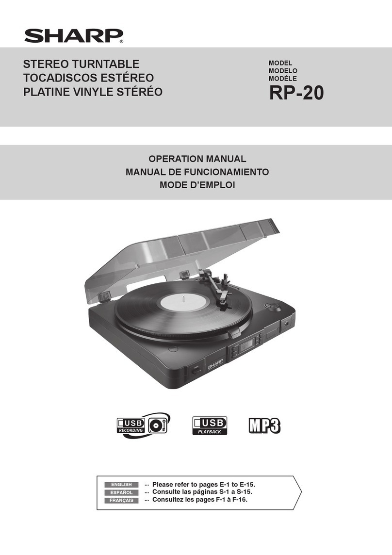
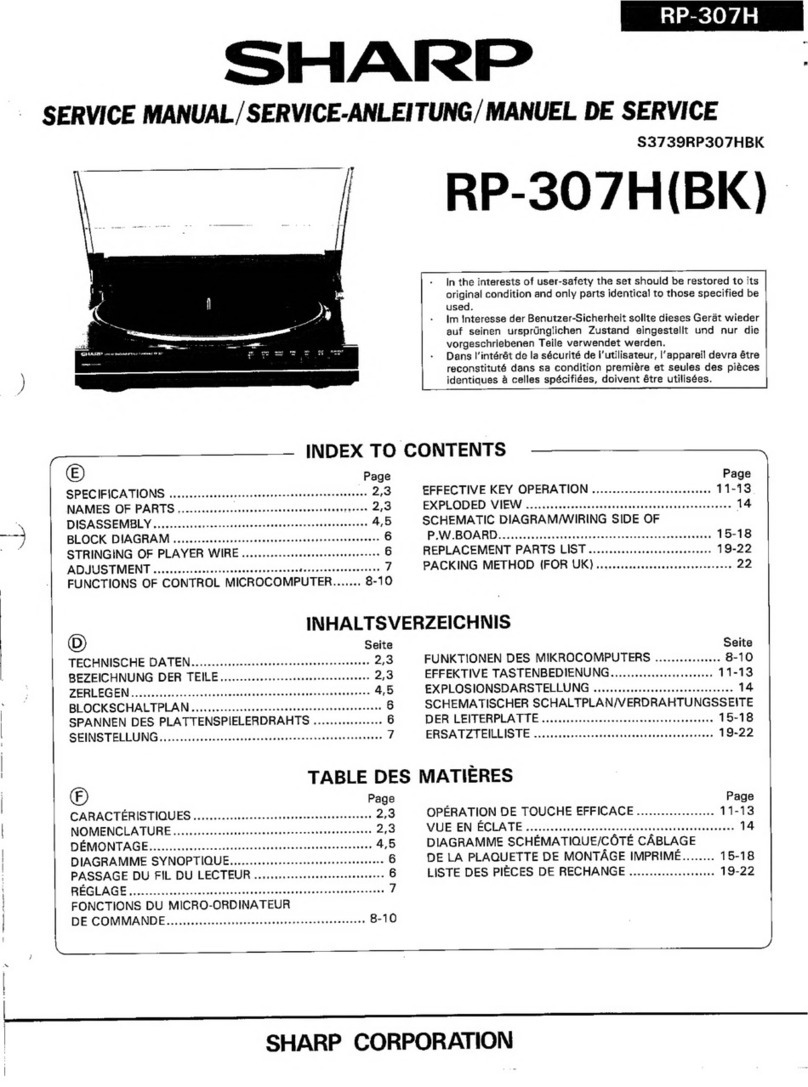
Sharp RP-205H User manual

SHARP
|
RP-205H(S).
SERVICE
MANUAL
/
SERVICE-ANLEI
TUNG
/
MANUEL
DE
SERVICE
$75C5RP-205HS
RP-205H(S)(BK)
RP-205E(BiK)
BQTH
SIDES
PLAY
cC_]
e®ln
the
interests
of
user-safety
the
set
should
be
restored
to
its
PHOTO:
RP-205H(S}
original
condition
and
only
parts
identical
to
those
specified
be
used,
elm
|nteresse
der
Benutzer-Sicherheit
soilte
dieses
Gerat
wieder
auf
seinen
urspriinglichen
Zustand
eingestelit
und
nur
die
vorge-
schriebenen
Teile
verwendet
werden.
®
Dans
l‘intérét
de
la
sécurité
de
l’utilisateur,
l'appareil
devra
étre
reconstitute
dans
sa
condition
premiére
et
seules
des
piéces
identiques
a4
celles
spécifiées,
doivent
étre
utilisées.
INDEX
TO
CONTENTS
()
Page
Page
SPECIFICATIONS
(2:4
aires
ean
a
ae
ora
eee
PES
SCHEMATIC
DIAGRAM..................
13,
14
NAMES
OF
PARTS.........0ccc0ceeevevas
2,3
WIRING
SIDE
OF
P.W.BOARD
............
15,
16
DISASSEMBLY:
hi
Sates
oe
3
Cte
oa
ee ee
4,5
NOTES
ON
SCHEMATIC
DIAGRAM............
17
STRINGING
OF
PLAYER
WIRE
.............
6
EQUIVALENT
CIRCUIT
(BLOCK
DIAGRAM)
BLOCK
DIAGRAM)
0
2
act
<i0
eee
Sark.
Cae
hs
SS
7
OE
Ga
at
aco
ke
ena
te
ered
1s
ati
aaa
eater
ee
18
MECHANICAL
ADJUSTMENT
.............4..
8,9
TYPES
OF
TRANSISTOR
AND
LED..........
19
CIRCUIT,
ADJUSTMENT
%s.
¢
4.4200
63s
acewe-e
ow
4
8,9
EXPLODED.
WI
EW
ico
ard
&
cea
waked
deed
aad
20,
21
INPUT/OUTPUT
PINS
OF
MICROCOMPUTER
REPLACEMENT
PARTS
LIST
.............
22—26
CIGTO
Ti
tatiows
<i
aie
t
Sate
see
Si
we
soca
Ae
10-12
PACKING
METHOD
(RP-205E
ONLY)
.........
26
INHALTSVERZEICHNIS
(0)
4
Seite
Seite
TECHNISCHE
DATEN..........
00000
e
ee
eee
2,3
SCHEMATISCHER
SCHALTPLAN,..........
13,
14
BEZEICHNUNG
DER
TEILE.............05-
2;3
VERDRAHTUNGSSEITE
DER
LEITERPLATTE.
15,
16
ZERLEGEN
aso
eae
ween.
©
XK
Gin
REM
OES
4,5
ANMERKUNGEN
ZUM
SCHEMATISCHEN
SPANNEN
DES
PLATTENSPIELERDRAHTS.....
6
SOHAL
TPA
5
60a
awe
Were
cares
Ce
Paw
es
17
BLOCKSCHALTPLAN.
.é
4-6.
¢0.54:02
8-0-0
e
ate
o
7
ERSATZSCHALTKREIS
(BLOCKSCHALTPLAN)
MECHANISMUSEINSTELLUNG..............,
8,9
DES
INTEGRIERTEN
SCHALTKREISES......
18
SCHALTUNGSEINSTELLUNG................
8,9
TRANSISTOREN-UND
LEUCHTDIODENTYPEN....19
EINGANGS-/AUSGANGSSTIFTE
DES
EXPLOSIONSDARSTELLUNG..............
20,
21
MIKROCOMPUTERS
(IC101)............
10-12
BREA
2
EE
LIST
Ewe
isd
68.
Se
ace
be
yet
oe
he
22--26
TABLE
DES
MATIERS
Page
;
Page
GARACTERISTIQUES
si.cwwae
Gonder
wage
«
2,3
COTE
CABLEAGE
DE
LA
PLAQUETTE
DE
NOMENCLATURE
yee
wes
Wee
a
4
cece
o-oo
a
le
ies
2,3
MONTAGE
iMPRIME..................
15,
16
DEMONTAGE
seit
ora
das
aa
anal
ewer
aaaraes
4,5
REMARQUES
CONCERNANT
LE
DIAGRAMME
PASSAGE
DU
FiL
DU
LECTEUR............
6
SCH
EMAVTOUE
tu.
45
sae
34
ca
dace
Wa
arene
eae
ate
17
DIAGRAMME
SYNOPTIQUE
................
7
CIRCUITS
EQUIVALENTS
(DIAGRAMME
REGLAGE
DE
MECANISME
................
8,9
SYNG@PMOUE)
DEC
es
6
eatin
ok
RY
Ras
oes
18
REGLAGE
DU
CIRCUIT..................0.
8,9
TYPES
DE
TRANSISTOR
ET
LED............
19
BROCHES
D‘'ENTREE/SORTIE
DU
VUE
EN
ECLATE
aN
ariec
(atuaerhh
ante,
ty
at
ee
tic
ea
el
Saecdeoat
20,
21
MICRO-ORDINATEUR
(IC101)...........
10—12
LISTE
DES
PIECES
DE
RECHANGE........
22-26
DIAGRAMME
SCHEMATIQUE.............
13,
14
SHARP
CORPORATION
Type:
Belt
drive,
full-automatic
Semiconductors:
1
LS!
10
[Cs
16
Transistors
20
Diodes
Q9LEDs
~
3
Photo
interrupters
2
Photo
transistors
Speed:
33-1/3
and
45
rpm
Motor:
DC
motor
Wow
and
flutter:
S/N
ratio:
OWONIAM
AWN
=
+
0.075%
(DIN
45
500)
‘65
dB
(DINB)
~
.
Power
Switch
.
APSS
Sensor
Level
Control
.
Play
Indicator
.
Speed
Button
Side
A/B
Button
and
Indicators
.
Introduction
Sean
Button
and
Indicator
.
Both
Sides
Button
and
indicator
.
Repeat
Button
and
{ndicator
.
Tonearm
Forward/APSS
Button
.
Tonearm
Reverse/APSS
Button
.
Cue
Button
—
.
Play/Cut
Button
.
Turntable
Compartment
.
Turntable
Open/Close
Button
.
Input/Output
Plug
FOR
A
COMPLETE
DESCRIPTION.
OF
THE
OPERATION
OF
THiS
UNIT,
PLEASE
REFER
TO
THE
OPERATION
MANUAL.
SPECIFICATIONS
Frequency
response:
Tracking
force:
Tonearm:
Cartridge:
Replacement
stylus:
Dimensions:
|
Weight:
prior
notice.
NAMES
OF
PARTS
Specifications
for
this
model
are
subject
to
change
without
20
—
20,000
Hz
3.09
Dynamic
balanced
Magnetic
type
STY-144
Width:
330mm
(13”}
.
Height;
100
mm
(3-31/32”)
Depth;
345
mm
(13-19/32”)
5.8
kg
(12.8
Ibs.)
13
14
Figure
2—1
Figure
2—2
Cr
eee
rete
ee
ne
aie
cet
een
Ce
ese
aes
Cree
am
;
et
a
os
eee
eet
ent
ne
me
ate,

EINE
VOLLSTANDIGE
BESCHREIBUNG
DER
BE-
DIENUNG
DIESES
GERATES
IST
IN
DER
BE-
DIENUNGSANLEITUNG
ENTHALTEN.
TECHNISCHE
DATEN
Typ:
Reimenantrieb,
vollautomatisch
Bestiickung:
1
LSI
10
integrierte
Schaltkreise
16
Transistoren
20
Dioden
9
Leuchtdioden
3
Photounterbrecher
2
Phototransistoren
Drehzahlen:
33-1/3
und
45
U/min
Motor:
Gleichstrommotor
Gleichlaufschwankungen:
+0,075%
(DIN
45
500)
Rauschabstand:
65
dB
(DIN
B)
Frequenzgang:
20
—
20
000
Hz
Auflagekraft:
3,0g
;
TPonarm:
Dynamisch
balanciert
'
Tanabnehmersystem:
Magnetischer
Typ
Ersatznadel:
STY-144
Abmessungen:
Breite:
330mm
Hohe:
100
mm
Tiefe:
345
mm
Gewicht:
5,8
kg
Die
technischen
Daten
fiir
dieses
Modell
kénnen
ohne
Ankiindigung
Anderungen
unterworfen
sein.
vorherige
BEZEICHNUNG
DER
TEILE
.
Netzschalter
.
APSS-Sensorpegelsteiler
.
Wiedergabeanzeige
.
Drehzahitaste
.
Tasten
und
Anzéigen
fiir
Seite
A/B
.
Einleitungs-Suchlauftaste
und
-anzeige
.
Taste
und
Anzeige
fir
beide
Seiten
.
Wiederholtaste
und
-anzeige
.
Taste
fiir
Tonarm-Voriauf/APSS
10.
Taste
fiir
Tonarm-Ricklaut/APSS
11.
Tonarmlifttaste
12.
Wiedergabe-/Unterbrechungstaste
13.
Schallplattenfach
14,
Taste
zum
Offnen/Schiie&en
des
Plattentellers
15.
Eingangs-/Ausgangsstecker
Oona
npand
—
POUR
LA
DESCRIPTION
COMPLETE
DU
FONC-
TIONNEMENT
DE
CET
APPAREIL,
SE
REPORTER
AU
MODE
D‘EMPLOI.
CARACTERISTIQUES
—
Entrainement
par
courroie,
auto-
matique
1LS)
aC!
16
transistors
20
diodes
9
LED
3
photo-interrupteurs
2
photo-transistors
Type:
Semi-conducteurs:
Vitesse:
33-1/3
et
45
t/mn
Moteur:
Moteur
CC
Pleurage
et
scintitlement:
+0,075%
(DIN
45
500)
Rapport
S/B:
65
dB
(DIN
B)
20
4
20
000
Hz
3,09
Equilibrage
dynamique
Réponse
en
fréquences:
Force
d‘appui:
Bras
de
lecture:
Cellule:
Type
magnétique
Aiguille
de
remplacement:
STY-144
Dimensions:
Largeur:
330
mm
Hauteur:
100
mm
Profondeur:
345
mm
Poids:
5,8
kg
Les
caractéristiques
de
ce
modéle
sont
sujettes
4
modifica-
tion
sans
préavis.
NOMENCLATURE
.
Commutateur
d’alimentation
.
Commande
de
niveau
de
senseur
APSS
.
Témoin
de
lecture
Bouton
de
vitesse
Bouton
et
témoins
de
face
A/B
.
Bouton
et
teémoin
de
balayage
d‘introduction
.
Bouton
et
témoin
de
deux
faces
.
Bouton
et
témoin
de
répétition
.
Bouton
d’avance
du
bras/APSS
10.
Bouton
d’inversion
du
bras/APSS
11.
Bouton
de
léve-bras
12.
Bouton
de
Jecture/rejet
13.
Compartiment
de
tourne-disque
14.
Bouton
d’‘ouverture/fermeture
de
tourne-disque
15,
Fiche
d‘entrée/sortie

Caution
on
Disassembly
Follow
the
below-mentioned
notes
when
disassembling
the
unit
and
reassembling
it,
to
keep
its
safety
and
excellent
performance:
1.
2.
3.
.
Take
sufficient
care
on
static
electricity
of
integrated
Take
out
a
record
of
the
unit.
Be
sure
to
remove
the
input/output
plug
from
the
SA-205H/E
before
starting
to
disassemble
the
unit.
Take
off
nylon
bands
or
wire
holders
where
they
need
be
removed
when
disassembling
the
unit.
After
servicing
the
unit,
be
sure
to
rearrange
the
leads
where
they
were
before
disassembling.
circuits
and
other
circuits
when
servicing.
REMOVAL
Cabinet
1.
Open
the
turntable
compartment*
1
2
Front
pane!
Main
P.W.Board
Turntable
compartment
*3
.
Move
forward
the
tonearm
*2
2.
Screw
Tonearm
block
*1:
Opening
the
turntable
compartment
is
possible
by
the
following
two
ways;
e
Connect
the
input/output
plug
to
the
Receiver
(SA-
205H/E),
turn
on
the
power
switch
and
push
the
open/close
button
to
open
the
turntable
compartment.
e
Loosen
the
screw
at
the
loading
motor
by
using
a
Phillips
screwdriver
at
the
rear
of
the
unit
and
then
shift
the
motor
so
that
the
turntable
compartment
can
be
opened
manually,
See
Fig,
4—2.
*2:
Moving
forward
the
tonearm
is
possible
by
the
following
two
ways;
e
Connect
the
input/output
plug
to
the
Receiver
(SA-
205H/E),
turn
on
the
power
switch
and
push
the
forward
button
to
move
forward
the
tonearm.
e
Apply
DC
10V
to
the
socket
CNS104
so
that
the
tonearm
is
moved
forward,
See
Fig.
4—2.
*3:
When
removing
the
turntable
compartment,
be
careful
not
to
put
undue
force
to
the
door
switch
(SW302).
Main
P.W.Board
DISASSEMBLY
Cabinet
a
Ne
rc
a
Front
Panel
(B)
x1
EC
63
x
5mm
SS
en
oe
|
f
a
Turntable
Compartment
Turntable
Compartment
"
Figure
4—2
Figure
4—3
Top
View
|
Phillips
Screwdriver
iat
Push

ZERLEGEN
Vorsichtsmassrege!n
fiir
das
zerlegen
Beim
Zerlegen
und
Zusammenbauen
des
Gerdtes
die
folgenden
Anweisungen
befolgen,
um
dessen
Betriebs-
sicherheit
und
ausgezeichnete
Leistung
aufrechtzuerhalten.
1.
Schallplatte
aus
dem
Gerat
entfernen,
2.
Vor
dem
Zerlegen
des
Gerates
unbedingt
den
Eingangs-/
Ausgangsstecker
aus
dem
SA-205H
ziehen.
3.
Nylonbander
oder
Leitungshalter
entfernen,
falls
dies
beim
Zerlegen
des
Gerates
erforderlich
ist.
Nach
Warten
des
Gerates
darauf
achten,
die
Leitungen
wieder
so
zu
verlegen,
wie
sie
vor
dem
Zerlegen
angeordnet
waren.
.
Beim
Ausfiihren
von
Wartungsarbeiten
auf
statische
Elektrizitat
der
integrierten
Schaltkreise
und
anderen
Schaltungen
achten.
iCH-
AB-
ITT
ENTFERNEN
VERFAHREN
BILDUNG
Gehause
1.Schraube
.....
(A}x9
2
Frontplatte
1,
Das
Schallpiattenfach
Offnen,
*1
2,.Schraube
.....
{B)x4
1.Schraube
.....
2.
Buchse
t.Schraube
.....
Hauptleiterplatte
e+
bP
we
ee
Scha}!plattenfach
*3
2,
Leiterplatten-
halterung.....
(F)
><
i
|
eee
ee
eee
(G)}
4,Schraube
.....
Tonarmblock
—
|
1.
Den
Tonarm
nach
vorne
bewegen,
*2
2.Schraube
.....
(ihx4
*1:
Das
kann
durch
die
folgenden
beiden
Méglichkeiten
erreicht
werden.
Offnen
des
Schallplattenfachs
e
Den
Ejingangs-/Ausgangsstecker
an
den
Receiver
(SA-2051)
anschlieRen,
den
Netzschalter
einschalten
und
die
Taste
zum
Offnen/SchlieRen
einschalten,
um
das
Schal!plattenfach
zu
6ffnen.
d
e
Die
Schraube
des
Antriebsmotors
vom
Lademotors
an
der
Gerdteriickseite
mit
einem
Kreuzschlitz-
schraubenzieher
lockern
und
den
Motor
so
drehen,
daR
das
Schallplattenfach
von
Hand
gedffnet
werden
kann.
(Siehe
Abb.
4—2),
*2:
Das
Verschieben
des
Tonarms
nach
vorne
wird
durch
die
folgenden
beiden
Méglichkeiten
erreicht.
e
Den
Ejingangs-/Ausgangsstecker
an
den
Receiver
(SA-205H)
anschlieBen
den
Netzschalter
einschalten
und
die
Vorlauftast
driicken,
um
den
Tonarm
nach
vorne
zu
bewegen.
»
Der
Buchse
CNS104
10
V
Gleichspannung
zufiihren,
so
da&
der
Tonarm
nach
vorne
bewegt
wird.
(Siehe
Abb.
4—2)},
*3-
Bein
SchlieRen
der
Schallplattenfachs
unbedingt
darauf
achten,
da&
auf
den
Schalter
zum
Tir
{SW302)
kein
iibermaRiger
Druck
ausgeiibt
wird.
*
So
BE
DEMONTAGE
Précautions
pour
le
démontage
Lors
du
démontage
de
I‘appareil
et
de
son
remontage,
suivre
les
précautions
ci-dessous,
pour
maintenir
ta
sécurité
et
d’excellentes
performances.
1.
Déposer
le
disque
de
|’appareil.
2.
Ne
pas
oublier
de
retirer
la
fiche
d’entrée/sortie
du
SA-205H
avant
de
démonter
l'appareil.
3.
Déposer
les
bandes
de
nylon
ou
tes
serre-cables
si
nécessaire
lors
du
démontage
de
l‘appareil.
Aprés
la
réparation
de
l’appareil,
s‘assurer
de
redisposer
les
fils
tel
qu’ils
étaient
avant
le
démontage.
.
Faire
attention
a
l’électricité
statique
des
circuits
intégrés
et
des
autres
circuits
lors
de
la
réparation.
|
pépose
pROcEDE
FIGURE
ee
(axa
Panneau
avant
,
Ouvrir
le
compartiment
de
tourne-disque.
*1.
PMI
principale
Compartiment
de
tourne-disque
4
+e
©
ew
we
eke
ed
_
PUN
NO
=|]
RO
.
Faire
avancer
le
bras
de
lecture.
*2
Bioc
de
bras
1:
Il
existe
deux
méthods
pour
ouvrir
le
compartiment
de
tourne-disque.
e
Mettre
/'appareil
en
marche
aprés
avoir
branché
la
fiche
d’entrée/sortie
a
I’ampli-tuner
{SA-205H)
et
appuyer
sue
le
bouton
d’ouverture/fermeture.
e
Pour
l’ouvrir
4
la
main,
déplacer
le
moteur
en
dévissant
cejui-ci
avec
un
tournevis
cruiciforme.
Voir
ja
Fig.
4—2.
2:
I!
existe
deux
méthodes
pour
faire
avancer
le
bras
de
lecture.
@
Mettre
l'appareil
en
marche
aprés
avoir
branché
la
fiche
dentrée/sortie
a
lJ'ampli-tuner
(SA-205H)
et
appuyer
sur
le
bouton
d‘avance.
e
Appliquer
Je
courant
continu
de 10
V
a
la
douille
CNS104.
Voir
la
Fig.
4—2.
*3:
Veiller
4
ne
pas
forcer
je
commutateur
d’porte
(SW302)
en
enlevant
le
compartiment.

®
STRINGING
OF
PLAYER
WIRE
J,
Turn
the
drurn
to
the
rest
position,
and
stretch
the
wire
in
2.
After
setting
the
wire,
turn
the
side
A/B
tonearm
to
its
the
numerical
order
as
shown
in
Fig.
6—1.
lead-in
position.
Refer
to
the
instructions
of
adjustment
of
tonearm
lead-in
position.
D)
SPANNEN
DES
PLATTENSPIELERDRAHTS
1,
Die
Trommel
bis
zur
Ruheposition
drehen,
dann
den
Draht
2.
Nach
Spannen
des
Drahts
den
Tonarm
fiir
Seite
A/B
zu
gemma
Abb.
6—1
in
der
numerischen
Reihenfolge
spannen.
seiner
Aufsetzposition
drehen.
Siehe
Anweisungen
fir
die
.
Einstellung
der
Tonarm-Aufsetzposition.
FP
PASSAGE
DU
FIL
DU
LECTEUR
1.
Tourner
fe
tambour
sur
la
position
d‘appui
et
passer
le
fil
2.
Aprés
avoir
passé
Je
fil,
tourner
le
bras
des
faces
A/B
sur
sa
dans
l’ordre
numérique
comme
le
montre
la
Fig.
6—1.
position
d’entrée.
Voir
les
instructions
du
réglage
de
la
position
d’entrée
du
bras
acoustique.
Pulley
(251)
Pulley
Shaft
(257}
Pulley
Base
(225)
Pulley
Assembly
(252)
~~
~
Pulley
Assembly
(252)
Pulley
(251}
Pulley
Shaft
(257)
Pulley
Base
(225)
Spring
{240}
Figure
6—1.
en
ils
Pee
te
mas
es
eta
enna
sem
Se
eee
eS

w
=
LO
oS
“
a.
oc
Adil+~
A60uLS
AAy
2010
"8010
EOl0~
1010
AS+
pinay
Addng
Jamo
101
X
@)
ano
"950
Nado
role
60!
31
bz
#)
HOON
13834
{6!)
"3S0
asing
tesay
Jolpu0D
3s015
T1I¥3
Joyo
C4
@uoog
noionns
{ey
OM
ENO~INID
C4]
@oNoHa
3SNVd
I3yIZ))
——
e0ldal
a
sai
a]
Sbsee
S30IS
HLoaKs)
ia
gcd
6}
ONINDVL
1vad3u
>?)
g
s3dis
OST
oe,
saint)
\—@&
prousios
rf
A
ira
oat
wiJDeuOL
10,0
Uk
wav
asouis
Aan
fe)
(53)
—{arv)
asind
b#
hy
oe
Olld
es]
“105
JGOuLS
Aa
@
i.)
:
~)
$o|@31
“a
UNIUD
LYHIs
pola
a
€
@PIS/Y
Pls
JaAug
oH
1#
Gy
PIS
5
agouis
sanf®
(an3}
O#
9010'SOld
Ge
ONTLAN
Saouis
Aan
)
a
——
O#
NI
ASKS)
4IN3419
zOlld
rOza31
IOlld
zozdat
wsuas
SSdV
“vv
soiga7q
80191
‘90191
|
UND
OLPNy
NS
EOI
td
‘20191
;
J
YHIAS
4004
——
#000
el
s08U@S
sey
ap
{IBD
3S019
HOO
4s3yt)
/
SS84PY.
YALNANOION
DIN
101
3]
ind
$iLno
(sXe)
-Bnjg
inding
|
a+
{UNIID
;DUBIS)GNOC2z]
©
Anda
(b)
(4N9I9
UIDW)
GNOUL)
| |
oO
©
x
:
.
[
_)
.
6d
Jndyng
s
tnduy|
ae.
Figure
7
BLOCK
DIAGRAM

©
MECHANICAL
ADJUSTMENT
Connect
the
Input/output
plug
to
the
Receiver
(SA-205H/E),
or
supply
+174
V
by
an
external
DC
power
supply.
ADJUSTMENT
Side
A/B
tonearm
lead-in
position
LP
record
.
Tonearm
clamp-
ing
wire
is
having
a
proper
tension
and
tonearm
is
moving
to
the
lead-in
position.
2.
Stylus
tip
is
at
the
central
part
of
the
lead-in
position.
Tonearm
clamp-
ing
wire
screw
or
fine
adjust-
ment
screw
*
See
Fig
8—1.
APSS
sensor
position
LP
record,
Hexagonal
wrench
APSS
sensor
adjustment
screw
*
See
Fig
8—2.
.
If
the
stylus
tip
maves
down
point
nearer
to
the
previous
program:
direction
2.
If
the
stylus
tip
moves
down
point
nearer
to
the
next
pra-
gram:
direction(B)
Side
A
33
r.p.m.
speed
:
VR101
45
r.p.m.
speed
:
VR102
Side
B
45
r.p.m.
speed
:
VR103
LP
record
which
is
provided
with
strobo
viewer
Phono
motor
rotational
speed
Phono
motor
is
kept
in
rotation.
Adjust
VR101,
VR102
and
VR103
in
this
order.
Connect
the
Input/output
plug
to
the
Receiver
(SA-205H/E),
or
supply
+14
V
by
an
external
DC
power
supply.
ADJUSTMENT
POINT
TONEARM
TRACKING
Side
A:
VR106
Side
B:
VR107
1,
Without
a
record
being
put
in
the
compartment,
push
the
cartridge
forward
key
first
and
then
the
cue
key
to
have
the
tonearm
moving
down
to
the
turntable
surface.
2,
Turn
the
semi-variable
resistor
clockwise
to
move
the
tonearm
in
the
inner
direction,
and
turn
it
back
until
the
tonearm
will
be
stopped:
at
this
position,
fix
the
semi-
variable
resistor.
APSS
SENSOR
SENSITIVITY
Side
A:
VR104
Side
B:
VR105
Pushing
the
cartridge
forward
key,
move
the
tonearm
to
the
lead-out
position
and
keep
the
unit
in
cue-up
mode.
(F517
*
1
Load
the
unit
with
a
test
record
(TOSHIBA:
LF-1003)
or
an
ordinary
LP
record
{as
clean
as
possible)
having
a
wide
lead-out
area.
Side
A
Adjustment
Screw
Side
8
Screw
Fine
Adjustment
Screw
Hexagonal
\,
Wrench
Record
Cartridge
Lead-in
Position
L
Center
Figure
8—3
LEAD-IN
POSITION
Hexagonal
Wrench
(1.27
mm)
Figure
8—2
APSS
SENSOR
POSITION
CIRCUIT
ADJUSTMENT
OSS
ESI
TPIOI
VRIOG
SIDE
A
smracr
YRC
“ey
VRIO6
VRIOT
SIDE
A
SIDE
B
‘Tracking
MAIN
P.W.B.
Orns
s
IDE
A
45rpm
Speed
VRIO2
AyVtsrpm
SIOEB
O@yvRios
Figure
8—3
ADJUSTMENT
POINTS
B:
Side
B
Adjustment
~
Figure
8—4
APSS
SENSOR
SENSITIVITY
Side
A/B
Selector
Switch
Electronic
Voltmeter
A:
Side
A
Adjustment
~~
eS
eo
ee

()
MECHANISCHE
EINSTELLUNG
Den
Ejingangs-/Ausgansstecker
an
den
Receiver
(SA-205H)
anschlieBen
oder
durch
eine
AuRengleichspannung
+14
V
zuleiten.
BE-
FOHRUNGS-
NENNUNG
LEHRE
EINSTELL-
PUNKT
Seite
A/B
Langspiel-
Tonarm-Klemm-
|
1.
Der
Tonarm-
Tonarm-
platte
drahtschraube
Klemmdraht
hat
Einjauf-
oder
Feineinstell-;
die
richtige
position
schraube
Spannung
und
*
Siehe
Abb.
8-1.
der
Tonarm
be
wegt
sich
zur
Einlaufposition.
2.
Die
Nadelspitze
befindet
sich
im
mittleren
Teil
der
Einlaufposition.
APSS-
Langspiel-
APSS-Sensor-
.
Wenn
sich
die
Sensar-
platte
Einstellschraube
Nadelspitze
an
position
Sechskant-
*
Siehe
Abb,
einer
Stelle
nahe
8—2.
zum
vorher-
gehenden
Pro-
gramm
absenkt:
Richtung(A)
2.
Wenn
sich
die
Nadel
an
einer
Stelle
naher
zum
nachsten
Pro-
gramm
absenkt:
RichtungB)
stiftsch!issel
Mit
Strobos-
kopmuster
versehen
Langspiel-
platte
Seite
A
Drehzahl
33
U/min:
VR101
Drehzahl
45
U/min:
VRi02
Seite
B
Drehzahl
45
U/min:
VR103
SCHALTUNGSEINSTELLUNG
Den
Eingangs-/Ausgansstecker
an
den
Receiver
(SA-205H)
anschlieRen
oder
durch
eine
AuRengleichspannung
+14
V
Platten-
spielermnotor-
Drehrichtung
Plattenspielermotor
dreht
sich
weiter,
VR101,
VR102
und
VR103
dieser
Reihe
nach
einstellen.
zuleiten.
Seite
A:
VR106
ABTASTUNG
|
Seite
B:
VR107
1.
Wenn
sich
keine
Schallplatte
im
Fach
befindet,
zuerst
die
Tonabehmer-Vorlauftaste
und
dann
die
Tonarmlifttaste
driicken,
damit
sich
der
Tonarm
auf
die
Plattenteller-
oberflache
absenkt,
.
Den
Trimmer
im
Uhrzeigersinn
drehen,
um
den
Tonarm
nach
innen
zu
bewegen,
dann
den
Trimmer
zuriickdrehen,
bis
der
Tonarm
zum
Stillstand
kommt;
in
dieser
Position
den
Trimmer
feststellen.
APSS-
SENSOR-
EMPFIND-
LICHKEIT
Seite
A:
VA104
|
Die
Tonabnehmer-Vorlauftaste
Seite
B:
VA105
|
driicken
und
den
Tonarm
zur
Auslaufpasition
bewegen;
das
Gerat
auf
Tonarmabhebung
eingestellt
lassen.
40+1mV
ie
ae)
*
4
In
das
Gerat
eine
Testschallplatte
(TOSHIBA:
LF-1003)
oder
eine
gewohnliche
Langspielplatte
{(mdglichst
sauber}
mit
groBem
Auslaufbereich
einlegen.
(@
REGLAGE
MECANIQUE
Brancher
la
fiche
d’entrée/sortie
su
|’ampli-tuner
(SA-205H),
ou
alimenter
le
courant
de
+14
V
CC.
POINTS
DE
ARTICLE
GABARIT
MESURE
REMARQUES
Disque
33
Vis
du
cable
tours
de
blocage
du
bras
ou
vis
de
réglage
fin.
“
Vor
la
Fig.
8-1.
Position
d'entrée
du
bras
faces
A/B
.
Le
cable
de
blocage
du
bras
a
ta
tension
correcte
et
Je
bras
se
déplace
vers
la
position
d’‘entrée,
2.
La
pointe
de
Vaiguille
est
sur
la
partie
centrale
de
la
position
d’‘entrée,
Position
du
Disque
33
senseur
APSS|
tours,
Clé
hexagonale
Vis
de
réghage
du
senseur
APSS
*
Voir
Ja
Fig.
8—2.
1.
Si
l’aiguille
descend
vers
UN
point
proche
du
pro-
gramme
précédent:
direction@)
2.
Si
la
pointe
de
Vaiguille
descend
vers
un
point
proche
du
pro-
gramme
suivant:
direction®)
Vitesse
de
rotation
du
moteur
du
phono
Disque
33
tours
fourni
avec
fe
viseur
strobo-
copique
Face
A
Vitesse
de
33
timn:
VR101
Vitesse
de
45
timn:
VR102
Face
8
Vitesse
de
45
timn:
VR103
Le
moteur
du
phono
est
laissé
en
rotation.
Régler
VR101,
VA102
et
VR103
dans
cet
ordre.
REGLAGE
DU
CIRCUIT
Brancher
la
fiche
d‘entrée/sortie
su
|’ampli-tuner
(SA-205H},
ou
alimenter
le
courant
de
+14
V
CC.
POINT
DE
PISTAGE
DU
:
1.
Sans
placer
un
disque
dans
le
BRAS
compartiment,
enfoncer
Ja
touche
d‘avance
de
ta
cellule
et
!a
touche
de
mise
en
pile
pour
que
le
bras
descende
sur
la
surface
du
plateau.
2.
Tourner
vers
fa
droite
la
résistance
semi-variable
vers
la
droite
pour
déplacer
le
bras
vers
j’intérieur
et
Ja
tourner
a
|‘envers
jusqu’a
ce
que
le
bras
s’arréte:
dans
cette
position,
fixer
la
résistance
semi-variable.
SENSIBILITE
DU
SENSEUR
APSS
En
enfoncant
la
touche
d‘avance
de
Ja
cellule,
déplacer
le
bras
vers
Ja
position
de
sortie
et
laisser
|’appareil
dans
le
mode
de
montée
de
mise
en
pile.
4021
mV
(*
1)
*
4
Charger
un
disque
d’essai
(TOSHIBA:
LF-1003)
dans
\‘appareil
ou
un
disque
33
tours
normal
{aussi
propre
que
possible}
qui
présente
une
large
zone
de
sortie.

RP-205H(S)
INPUT/OUTPUT
PINS
OF
Input/
|
nee
|
Si
Application
Input
|Detection
of
tonearm
position
Input
|Detection
of
tonearm
position
Input
|
Cartridge
output
Input
{This
signal
becomes
Low
level
when
a
space
between
the
programs
fs
detected.
KEY
IN
#0
KEY
IN
#1
KEY
STROBE
#0
KEY
STROBE
#1
KEY
STROBE
#2
KEY
STROBE
#3
KEY
STROBE
#4
KEY
STROBE
#5
INTRO
REPEAT
BOTH
SIDES
REC
START
Input
jKey
matrix.
Input
Key
matrix.
Output
|Key
matrix.
Output
{Key
matrix,
Output
|
Key
matrix.
Output
|
Key
matrix,
Output
|
Key
matrix.
Output
|
Key
matrix.
Output
{Intro
indicator
Output
|
Repeat
indicator
Output
|
Both
sides
indicator
Output
|
This
causes
the
tape
deck
to
start
recording,
REC
PAUSE
Output
|
This
signal
causes
the
tape
deck
to
stop
recording
momentarily.
FUNCTION
CALL
Dutput
|
This
signal
cause
the
stereo
amplifier
to
be
set
at
the
PHONO
position.
RESET
Reset
TEST
GND
OSC
1
osc2
*
DOOR
(V)
OPEN
|
Output
DOOR
(G)
CLOSE!
Output
Earth
Clock
oscillation
Clock
oscillation
Opening
of
loading
moter
Closing
of
loading
motor
MICROCOMPUTER
(IC
101)
Input/
PHONO
PHONO
@)
FWD
FWD
|
Output
|
Forward
rotation
of
phono
motor
PHONO
)
REV
|
Output
|
Reverse
rotation
of
phono
motor
33/45
Output
|
This
signal
becomes
High
level
when
the
record
is
played
at
the
speed
of
So
rpm.
and
becomes
Low
level
when
it is
played
at
the
speed
of
45
r.p.m.
29
TRACKING
Output
|
This
signal
becomes
High
level
when
the
tonearm
starts
tracking
on
the
record
surface.
30
ARM
()
FWD
Output
|
Tonearm
forward
moving
31
ARM
()
REV
Output
|
Tonearm
reverse
moving
32
SOL
PULSE
Output
|
This
pulse
becomes
High
level
when
the
solenoid
is
attracted.
33
SOLA
Output
|
Tonearm
solenoid
for
side
A
34
SOL
8B
Output
|
Tanearm
solenoid
for
side
B
35
SIDE
A/SIDE
B
Output
|
Side
A/Side
B
indicator
36
MUTING
Output
|
This
signa!
becomes
Low
level
when
the
unit
is
in
playback
mode.
37
PLAY
Output
|
Play
indicator
38
HOLD
—
_-
39
INT
a
~
40
Vop
— -
41
{DOOR
OPEN
SW
Input
|
This
signal
becomes
Low
level
when
the
turntable
compart-
ment
is
open.
42
IDOOR
CLOSE
SW]
Input
|
This
signal
becomes
Low
level
when
the
turntable
compart-
ment
is
closed.
—10—
“sropee:
at!
y

Se
ee
ee
Ss
~
a
a
a
OT
ee
ae
er
(©)
EINGANGS-/AUSGANGSSTIFTE
DES
MIKROCOMPUTERS
(IC
101)
=
REST
Eingang
|
Feststetlung
der
Tonarmposition
ADRESS
AUDIO
‘APSS
1
Eingang
|
Feststellung
der
Tonarmposition
Eingang
|
Tonabnehmerausgang
Dieses
Signal
erreicht
einen
niedrigen
Pegel,
wenn
zwischen
den
MusikstUicken
ein
Leerraum
festgestellt
wird.
Eingang
KEY
IN
#0
Eingang
|
Tastenmatrix
KEY
IN
#1
Eingang
|
Tastenmatrix
KEY
STROBE
#0
KEY
STROBE
#1
KEY
STROBE
#2
KEY
STROBE
#3
KEY
STROBE
#4
KEY
STROBE
#5
INTRO
REPEAT
BOTH
SIDES
REC
START
Ausgang
|
Tastenmatrix
Ausgang
|
Tastenmatrix
Ausgang
|
Tastenmatrix
Ausgang
|
Tastenmatrix
Ausgang
|
Tastenmatrix
Ausgang
|
Tastenmatrix
Ausgang
|
Einteitungsanzeige
Ausgang
|
Wiederhalanzeige
Ausgang
|
Anzeige
fiir
beide
Seite
Dadurch
wird
das
Cassettendeck
in
die
Aufnahme-Betriebsart
geschaltet.
Ausgang
REC
PAUSE
Dieses
Signal
verursacht
ein
augenblickliches
Anhalten
der
Aufnehme.
Ausgang
FUNCTION
CALL
Dieses
Signal
schaltet
den
Stereo-
Verstarker
auf
“PHONO”
um,
Ruickstellung
Ausgang
RESET
TEST
GND
Masse
OSC
1
Taktgeber
OSC
2
Taktgeber
DOOR
@)
OPEN
|
Ausgang
|
Offnen
des
Lademotors
25
jDOOR
™)
CLOSE}
Ausgang
|
SchlieRen
des
Lademotors
26
|
PHONO
(@)
FWD
PHONO
()
REV
33/45
TRACKING
ARM
@)
FWD
ARM
@)
REV
SOL
PULSE
SOLA
SOLB
SIDE
A/SIDE
B
MUTING
PLAY
HOLD
INT
Vop
DOOR
OPEN
SW
42
|DOOR
CLOSE
sw
4g
Ausgang
Ausgang
Ausgang
Ausgang
Ausgang
Ausgang
Ausgang
Ausgang
Ausgang
Ausgang
Ausgang
Ausgang
Eingang
Eingang
Anwendung
Plattenspieiermotor-Vorlauf
Plattenspielermotor-Ricklauf
Dieses
Signal
erreicht
einen
hohen
Pegel,
wenn
die
Schall-
platte
bei
33
U/min
abgespielt
wird,
Beim
Abspielen
mit
45
U/min
sinkt
der
Signalpegel
ab,
Dieses
Signal
erreicht
einen
hohen
Pegel,
wenn
die
Schall-
piatte
abgetastet
wird.
Tonarm
(Bewegung
nach
vorne}
Tonarm
(Bewegung
nach
hinten})
Dieser
Impuls
erreicht
einen
hohen
Pegel,
wenn
der
Tonarm-
tauchmagnet
angeregt
wird,
Tonarmtauchmagnet
fur
Seite
A
Tonarmtauchmagnet
fiir
Seite
B
Anzeige
fiir
Seite
A/B
Dieses
Signal
erreicht
einen
niedrigen
Pege!,
wenn
sich
das
Gerdt
in
der
Wiedergabe-
Betriebsart
befindet.
Wiedergabeanzeige
Dieses
Signal
erreicht
einen
niedrigen
Pegel,
wenn
das
Schail-
-
plattenfach
geschlossen
wird.
Dieses
Signal
erreicht
einen
niedrigen
Pegel,
wenn
das
Schall-
plattenfach
geschlossen
wird,
Oh
a
nd
me
da
se
ar
ae
mm
ena

eer
ere
te
rec
he
Leen
REST
ADRESS
AUDIO
APSS
KEY
IN
#0
KEY
IN
#1
KEY
STROBE
#0
KEY
STROBE
#1
KEY
STROBE
#2
KEY
STROBE
#3
KEY
STROBE
#4
KEY
STROBE
#5
INTRO
REPEAT
BOTH
SIDES
REC
START
REC
PAUSE
RESET
TEST
GND
OSC
1
OSC
2
DOOR
@
OPEN
Entrée/
sortie
Entrée
Entrée
Entrée
Entrée
Entrée
Entrée
Sartie
Sortie
Sortie
Sortie
Sortie
Sortie
Sortie
Sortie
Sortie
Sortie
Sortie
FUNCTION
CALL
|
Sortie
Sortie
Application
Détection
de
Ja
position
de
bras
Détection
de
la
position
de
bras
Sortie
de
cellule
Ce
signal
passe
au
bas
niveau
quand
un
espace
entre
morceaux
est
détecté.
Martice
de
touche
Martice
de
touche
Martice
de
touche
Martice
de
touche
Martice
de
touche
Martice
de
touche
Martice
de
touche
Matrice
de
touche
Témoin
d‘introduction
Témoin
de
répétition
Témoin
de
deux
faces
Départ
de
l’enregistrement
par
la
platine
4
cassette
Arrét
momentané
de
l‘enregistrement
par
la
platine
a
cassette
Réglage
de
l’ampli
stéréo
sur
“PHONO”
Remise
a
zéra
Mise
a
la
terre
Oscillation
d’horloge
Oscillation
d‘hortoge
Ouverture
du
moteur
de
chargement
28
29
30
31
32
33
35
36
37
38
39
40
41
42
—12—
DOOR
@)
CLOSE
PHONO
()
FWD
PHONO
(WV)
REV
33/45
TRACKING
ARM
(WV)
FWD
ARM
@)
REV
SOL
PULSE
SOLA
SOL
8
SIDE
A/SIDE
B
MUTING
PLAY
HOLD
INT
Vopb
DOOR
OPEN
SW
DOOR
CLOSE
SW
Entrée/
sortie
Sortie
Sortie
Sortie
Sortie
¥
Sortie
Sortie
Sortie
Sortie
Sortie
Sortie
Sortie
Sortie
sortie
Entrée
Entrée
Application
Fermeture
du
moteur
de
chargement
Ratation
du
moteur
phono
Rotation
inverse
du
moteur
phono
Ce
signal!
passe
au
haut
niveau
au
cours
de
ja
lecture
4
33
t/mn
et
passe
au
bas
niveau
au
cours
de
Ja
lecture
a
45
t/mn.
Ce
signal
passe
au
haut
niveau
quand
le
bras
commence
a
poursuivre
le
siilon
du
disque.
Avance
du
bras
Retour
du
bras
Cette
impulsion
passe
au
haut
niveau
quand
le
solénoide
est
attiré.
Soténoide
de
bras
pour
la
face
A
Solénoide
de
bras
pour
Ja
face
B
Témoin
des
fase
A/B
Ce
signal
passe
au
bas
niveau
quand
l'appareil
est
en
mode
de
lecture.
Témoin
de
lecture
Ce
signa!
passe
au
bas
niveau
quand
te
compartiment
de
tourne-disque
est
ouvert.
Ce
signal
passe
au
bas
niveau
quand
le
compartiment
de
tourne-disque
est
fermé.

RP-205H(S)
—
RP-205H(S)
ns
oe
oe
a
Se
Be
ee
ee
ee
ee
a
as
NO
MAIN
PWB-
Al
CNPION
=
CNSIOI
co=i
INPUTS.
CNPIO2
DID4
swao2
cnpios}
«CNSIOS
=
Doo
oS
ee
in
at!
con
=
|
BA
i
oe]
=
aval
+
=a
=
CARTRIDGE
ADRESS/REST
SENSOR
PWB-B
CNSIOT
CNPHIOT
Fl
Reorss
—
a
pion
Ske
HONG
MOTOR
uy
QI05,0I06
2SC2878
B
By
Xe)
a
a17B~
Age
R2zza~A22z
[10K
C139,
C140,
C142
.
0.001
Roza
eeu
Icioa
|R3702
OPE,
AMP.
AWS)
Che
pics
2.3¥
2.2%
paee
Issi
270
wawi
DRIVER
Icios
IClOyF)
=:
IR2339
OPE.
AMP
MOTOR
CONTROL
cies
RITA
mflav
100K
TT
rt—“
CY
CdS
eiDE
A
APSS
REMSOR¢
ry
Icio
=BAGZIE
GHD SUD
ee
CX
EXaKAXSXEX7
LI
XS)
aoyv
oy
|
a
|
eae)
rg
Bai
(S
SEQUENCE
LED
REST
=
SENSOR
33/45
|
ADRESS
SENSOR
Pi
vee
PHONO
M
REV
PHONG
M
FWD
FUNCTION
poor
VO
CALL
M
CLOSE
DOGR
Rie?
Ps
“y
MOS.
CNSIO4
rt}
Tj]
fi
CARTRIDGE,
T
tit
A
GOTOR
CNB
sae
Pea
a
ibe
ee
ae
a
re
"|
an
ig
b,
|
(ele
Qui-Qu3
254562
Y
1clgz
MS4547P
Sane
RIG
te
DIOg
Alé3~
RIGS
LSkK
O¢aW)
MOTOR
CONTROM.
ey
Rae
MOTOR
CONTROL
|clo9
«=BAG2/B
Guo
GHO
vee
A
a
Be
COXEXSKEXSXEXTXEXS)
—
are
a
——t
a
i
aT
tH
STi
ge
go”
——
1
woz
SSit,
iy
be
pe
|
TS
|
lea)
LEDIO)~LEDIOS:
GL-3PRS
LEDIO!
:
REPEAT
LEDIOG:GLSPROOZ!
LEpIO2;
BOTH
SIDES
CNPIOG
CNSID6
LECIO3:
INTRO
"
.
5
esl
2scir4o
Rj
LEDS
oe
-
=
Li
ds.
LA
LEDiOG!
PLAY
Z
.
:
oe
fo
cereae
ATK
s
|
:
;
&
AIo3
iD
Qiol
2snle73
Lint
+
‘
alo2,QI04.0109
25CI740
R
(s513a
at
f)
-4
NM
2
70
iol
:
Bit
Qios
2SAI0I5
GR
|
“.
e
NOTES
ON
SCHEMATIC
DIAGRAM
can
be
found
on
page
17.
e
ANMERKUNGEN
ZUM
SCHEMATISCHEN
SCHALTPLAN
stehen
auf
Seite
17.
aks
:
A\
|
s
Oxirey
a
gN
BTS
|
=
HT
ee
|
Rest
oy
a
=
rf
=
A
|
|
|
1
|
!
Cc
[
fo
4
7
i
eae
piilel
|
ol
0)
Ie
i]
oh
I
ot
~
$
ta
Caen
RCS
ae
ea
||
.
|
e
REMARQUES
CONCERNANT
LE
DIAGRAMME
SCHEMATIQUE
sont
indiquées
a
la
page
17.
a
a
es
oe
i
ee
Figure
13
SCHEMATIC
DIAGRAM
ee
ic
—
14
—

ne
areas
ee
terre
ae
gat
ee
}
CNS
(09
|
RP-205H(S):
=RP-205H(S)
SI
ea
(SS
OS
(AT
ARENT
(MRT
GGRASESN
(ESS
RSNA
RUINS
A
avON
DRAG]:
CRRA
Re
[EN
GAS
|
SIDE
A
TONEARM
ASSEMBLY
M102
MIOl
LOADING
PHONO
MOTOR
MOTOR
REQ,
BLACK
“O*
{is
4
[naa
BLUE
CNSIIO
BROWN
ORANGE
2
To
TURNTABLE
CHASSIS
(GND)
SOLION
16
TONEARM
_
SOLENOID
GAEEN
BLUE
———
==
==.
RED
SIDE
B
TONEARM
ASSEMBLY
iz
cata
|
|
(@PSSSENSORPWB-F)
~~
>>
SSS S==
R=
=
JUMPER
PWB-D
eel
WSOF
OPEN/CLOSE
SWITCH
P.W.B.-A2
Cc
CARTRIDGE
WHITE
BROWN
CNSs|O2
-eustuayee
wo
t
sovice
TONEARM
»
GREG
«
Qo
Ke
{
ip
SOLENOID
=—
TRACKING
BG
:
CARTRIDGE
SENSOR
15
ADRESS/REST
SENSOR
PW.B.-B
Velie
8
yet
Hts
Ls
BE
|
PE
:
‘
as
.
PUP
Tpyos.:
ate
es
age
e
ED
EDI
ssswewrivic
rea
bea
|
|
snow
a
VAISALA
aids
sqrt
saat
Magy
mga
|
JG
oni
Oe
a
we
US.
&
Eyota
:
Pe
es
a
ee
Se
~ $
:
‘
iw
Pi
tbe
Pay,
i)
wn
a
t
ia
meg
eae
rs
Worn
‘ais
EL
ae’?
Sores
[martes
Y
Ys
ep
es
B
pCR
;
ae
le
ir
Key
ee
@
Atos
-—Wwe—:
CNPND1
i
48
ay
a
Bib
ogy
eS
nite
Bi
=
'
P
=
“;
“HE
ES
RSW
Rito
Mapa
"
aN
Me
BIL
RIB
NED",
:
101
ne
—W—A200
.
ae
<
v,
2
fe
ND
ae
a
i
=
faye
vale
Ait
.
;
po
ws
CNSIOS
2
[
NROOSOODOOM
4.44
.
3
; :
——>—
Reet
u
hed
tae
Ses
:
:
3)
pp
ci12:
gg
ey
ee
ee
oe
Se
AW
“
es
Nt
ig
|
Ape.
Be
|
1.
—4b—C108
CIG.
~QW
R225,,
TO
BAe
oat?
Mirage
Te
ANA
an
:
oh
vu
-
-
|"
;
_
1
er
re
|
me
AG
Wk
ft
3
-=
i
to}
0)
~
papery
ere
ererereray
<y
<)
[.
fensiog
9.0
5!
:
fe
-
+
RISS
GEH\ali2
6431
“8
AI5S.
Bre
ee
aca
‘sm
eS
i
|
dh
Q111
CNPIO
Aree
|
bx
2
|
uP
1o4—wele!
,
Q103
fc:
.
LIOS
aes
G&.
SIDE
A
:
WRIOU
APSS
ORANGE
3
5
§
RHO
OOADIUL
Cure
OOOO
Ot
tl
NY
Pa
Fy
ae
mi
éiey
:
SUV-O
H13B
1
F2119AFAL
[
177,
TRACKING.
os
cin
:
Pa
:
Fe
Als?
:
'
SIDIE
8
SIDIE
A,
45;
—.
; ;
re
—
Pe
ee
ae
ae
ee
oe
Sx
ett
ia
ae
“Teo:
. :
RIG?
pan
eee
g
oer
etre
8
is
as.
*
.
SPEED
eye
z
et
ee
SHLO
MS
cd
a =
1
cas}
Saya
ote
oR
sede
=
LEDIOS:
te
eS
kee
ab
sWi11
fe
eG
«
MS
Be
7
Jeunes
FR
geNgoRD
TE
gtoget
|
-
:
;
claLeoiog
L.!
:
clas
LED101!
ae
clgoL£0103
Loe
per
FED105
i
i
HaNwk
ce
=a
faith
ice
=
Path
ice
od
nor
a
swios
a]
Sswiid
“Hl.
does
=
os
er
2
—_
ae
CUE
REV
FWD
ee
Ss
fine
ga
=
=
PLAY
/CUT
REPEAT
BOTH
SIDES
INTRO
SIDE
B/
SIDE
A
fete
I
ee
oe
a
eee
ee
Figure
15
WIRING
SIDE
OF
P.W.BOARD
o
—
15
—
—16—
INPUT/OUTPYUT
PLUG
CNS
10)
7

©
e
Resistor:
©
©
To
differentiate
the
units
of
resistors,
such
symbols
as
K
and
M
are
used:
the
symbol
K
means
1000
ohm
and
the
symbol
M
means
1000
kohm
and
the
resistor
without
any
symbols
is
ohm-type
resistor.
Capacitor:
To
indicate
the
unit
of
capacitor,
a
symbol
P
is
used:
this
symbol!
P
means
micro-micro-farad
and
the
unit
of
the
capacitor
without
such
symbol
is
microfarad.
As
to
elec-
trolytic
capcitor,
the
expression
“capacitance/withstand
voltage’
is
used.
(CH),
(TH},
(RH),
(Ud):
Temeprature
compensation
Power
Switch
APSS
Sensor
Level
Control!
Switch
Play/Cut
Switch
Cue
Switch
Tonearm
Reverse
Switch
Tonearm
Forward
Switch
Repeat
Switch
Both
Sides
Switch
Introduction
Scan
Switch
Side
A/B
Switch
Speed
Switch
Open/Close
Switch
Door
Switch
(This
switch
is
interlocked
with
motion
of
the
turntable
compartment.)
Widerstande:
Um
die
Einheiten
der
Widersténde
unterscheiden
zu
kon-
nen,
werden
Symbole
wie
K
und
M
benutzt.
Das
Symboi
K
bedeutet
1000
Ohm
und
das
Symbol
M
1000
Kilo
ohm;
Bei
Widerstéanden
ohne
Symbol
handelt
es
sich
um
ohmsche
Widerstande,
Kondensatoren:
Zum
Bezeichnen
der
Kondensatoreinheit
wird
das
Symbol
P
benutzt;
dieses
Symbol!
P
bedeutet
Nanofarad.
Die
Einheit
eines
Kondensatore
ohne
Symbol
ist
Mikrofarad,
Fir
Elektrolytkondensatoren
wird
die
Bezeichnung
“Kapazitat/Stehspannung”
benutzt.
(CH),
(TH),
(RH),
(UJ);
Temperaturkompensation
Résistance:
Pour
différencier
les
unités
de
résistances,
on
utilise
des
symboles
tels
que
K
et
M:
le
symbole
K
signifie
1000
ohms,
te
symbole
M
1000
kohms,
et
Je
résistance
donn-ée
sans
sy
MBO
est
une-résistance-de-type-ohm.-—__—___~--
i
mpertantes-poure-maintein_de-la-sécurité-—S-assurerde-les—__.
Condensateur:
Pour
indiquer
l‘unité
de
condensateu,
on
utilise
le
symbole
P:
ce
symbole
P
signifie
micro-microfarad,
et
l’unité
de
condensateur
donnée
sans
ce
symbole
est
le
microfarad.
En
ce
qui
concerne
te
condensateur
électrolytique,
on
utilise
‘expression
“tension
de
régime/capacité”’
(CH),
(TH),
(RH),
(UJ);
Compensateur
de
température
DESCRIPTION
RP-205H(S)
NOTES
ON
SCHEMATIC
DIAGRAM
e
The
indicated
voltage
in
each
section
is
the
one
measured
by
Digital
Multimeter
between
such
a
section
and
the
chassis
with
no
signal
given.
»®
Parts
marked
with
“4
’'{:-.)
are
important
for
maintaining
the
safety
of
the
set.
Be
sure
to
replace
these
parts
with
specified
ones
for
maintaining
the
safety
and
performance
of
the
set.
e
Schematic
diagram
and
Wiring
Side
of
P.W.Board
for
this
model
are
subject
to
change
for
improvement
without
prior
notice.
POSITION
OPEN—CLOSE
ANMERKUNGEN
ZUM
SCHEMATISCHEN
SCHALTPLAN
*
Die
in
den
einzelnen
Teilen
angegebenen
Spannungen
werden
mit
einem
Digitalvielfachme&gerat
zwischen
dem
betreffen
den
Teil
und
dem
Chassis
ohne
Signalzuleitung
gemessen.
e
Die
mit
A
(#8)
bezeichneten
Teile
sind
besonders
wichtig
fiir
die
Aufrechterhaltung
der
Sicherheit.
Beim
Wechse!n
dieser
Teile
sollten
die
vorgeschriebenen
Teile
immer
verwendet
werden,
um
sowohl
die
Sicherherheit
als
such
die
Leistung
des
Gerdtes
aufrechtzuerhalten.
e
Anderungen
des
schematischen
Schaltplans
und
der
Verdrahtungsseite
der
Leiterplatte
flir
dieses
Modell
im
Sinne
von
Verbesserungen
jederzeit
vorbehalten.
REMARQUES
CONCERNANT
LE
DIAGRAMME
SCHEMATIQUE
|
e
La
tension
indiquée
dans
chaque
section
est
celle
mesurée
par
un
multimétre
numérique
entre
Ja
section
en
question
et
le
chassis,
en
l'absence
de
tout
signal.
e
Les
piéces
portant
la
marque
A
(:.)
sont
particuligrement
remplacer
par
des
piéces
du
numéro
de
piéce
spécifié
pour
maintenir
Ja
sécurité
et
la
performance
de
|’appareil:
e
Le
diagramme
schématique
et
le
cété
cablage
de
la
PMI
de
ce
modéle
sont
sujets
4
modifications
sans
préavis
pour
‘amélioration
de
ce
produit.
-—i7—

BA6218
IR2339
CHE
i
-
i
LA5512
1R3702
OUTPUT2[
1.
Top
View
Top
View
Figure
18
EQUIVALENT
CIRCUIT
(BLOCK
DIAGRAM)
OF
IC
—18—
haJOUTPUT3
h3]OUTPUT4

ee
ee
-
=.
ee
Ce
en
ee
ee
Noe
dee
apttay!
ears,
Aes
J:
2
Sethe
enn
ae
ne
ae
ee
.
aE
a
Ti
E5:
Cie
es
Waser
cet
ea
=
Bee
oa
oF
es
Fe
a
aca
ie,
0
nee
ee
ee
ee
"
Ga
ae
2SA966
Y
2$D1273
GP3S12
GL-352
PT-350C
2$C2236
Y
White
Black
C
oo0
2SA1015
GR
28J103
GR
2SA562
Y
2SC1740
R
GL-3PR9
28C2878
B
ON1128
GL520
GL5PRO002
noo
oc
oo
Figure
19
TYPES
OF
TRANSISTOR
AND
LED
wt
|
—19—

Figure
20
CABINET
EXPLODED
VIEW
(1/2)
=
50
=
re
te
en
a
in
re

Wee
—.
pate’
—,
Figure
21
CABINET
EXPLODED
VIEW
(2/2)
a
2

RP-205H(S)
©
©
:
LISTE
DES
PIECES
DE
RECHANGE
“COMMENT
COMMANDER
DES
PIECES
DE
RECHANGE”
REPLACEMENT
ERSATZTEILLISTE
PARTS
LIST
“HOW
TO
ORDER
REPLACEMENT
PARTS"
“BESTELLEN
VON
ERSATZTEILEN”
To
have
your
order
filled
promptly
and
correctly,
please
furnish
the
following
Um
Ihren
Auftrag
schnell
und
richtig
ausfuhren
zu
k6nnen,
bitten
wir
um
die
folgenden
Angaben.
1,
MODELLNUMMER
2.
REF.
NR.
3.
TEIL
NR.
4.
BESCHREIBUNG
Pour
voir
votre
commande
exécutée
de
maniére
rapide
et
correcte,
veuillez
fournir
les
renseignements
suivants.
1.
NUMERO
DU
MODELE
2.
N°
DE
REFERENCE
3.
N°
DE
LA
PIECE
4.
DESCRIPTION
information.
1.
MODEL
NUMBER
2,
REF.
NO.
3.
PART
NO.
4.
DESCRIPTION
NOTE:
Parts
marked
with
“A\"
are
important
for
maintaining
the
safety
of
the
set.
Be
sure
to
replace
these
parts
with
specified
ones
for
maintaining
the
safety
and
performance
of
the
ANMERKUNGEN:
Die
mit
AV
bezeichneten
Teile
sind
besanders
wichtig
fur die
Aufrechterhaltung
der
Sicherheit.
Beim
Wechseln
dieser
Teile
sollten
die
vorgeschriebenen
Teile
immer
verwendet
NOTE:
Les
piéces
portant
la
marque
A,
sont
particuliérement
importantes
pour
le
maintien
de
la
securité.
S’assurer
de
ies
remplacer
par
des
piéces
du
numéro
de
piéce
spécifié
pour
we
DD
te
set.
werden,
um
sowohl
die
Sicherheit
ais
auch
die
maintenir
la
sécurité
et
la
performance
de
|'
Leistung
des
Gerdtes
aufrechtzuerhalten.
appareil.
REF.NO.
PART
NO.
DESCRIPTION
CODE
REF.NO.
PART
NO.
DESCRIPTION
CODE
D106
VHD1S8133//-i1
Silicon,
1$$133
AA
INTEGRATED
CIRCUITS
D107
VHD1SS133//-1
Silicon,1S$133
AA
D108
VHD1SS133//-1
—
Silicon,1$S133
AA
1C101
RH-iX1309AFZZ
Microcomputer
AT
D109
VHD1$$133//-1
—
Silicon,1SS133
AA
1102
VHiM54547P/-1
Motor
Control,M54547P
AL
D110
VHD1S$133//-1
—
Silicon,1S$133
AA
1103
RH-iX1215AFZZ
C-MOS
QUAD
Analog
AH
D111
VHD1S88133//~-1
Silicon,1$$133
AA
;
Switch,
MC14066BCP,
D112
VHD1S8133//-1
—
Silicon,1$S133
AA
LC4066B
D113
VHDIIE1TA2/-1
Silicon,
l1E1TA2
AB
IC104
VHi
iR2C30//-1
—Driver,JR2C30
AG
D114
VHDL1E1TA2/-i
Siticon,
L1IE1TA2
AB
IC105
VHiiR2C30//-1
Driver,tR2C30
AG
D115
VHD1S8133//-1
—
Silicon,1SS133
AA
IC106
RH-iX1215AFZZ
C-MOS
QUAD
Analog
AH
D116
VHD1$$133//-1
=
Silicon,1SS133
AA
Switch,
MC14066BCP,
D117
VHD1SS8133//-1
Silicon,
1SS133
AA
LC4066B
D120
VHD18$133//-1
—
Silicon,1$$133
AA
1C107
VHiiR2339//-1
Comparator,IR2339
AH
LED101
VHPGL-3PR9/-1
LED,Red,GL-3PR9
AB
C108
VHiiR3702//-1
Operational
Amplifier,
AH
LED102
VHPGL-3PR9/~-1
LED,Red,GL-3PR9
AB
1R3702
LED103
VHPGL-3PR9/-1
LED,Red,GL-3PR9
AB
10109
VHiBA6218//-1
Motor
Controi,BA6218
AH
LED104
VHPGL-3PR9/-1
LED,Red,GL-3PR9
AS
IC110
VHiBA6218//-1
Motor
Controi,BA6218
AH
LED1O5
VHPGL-3PR9/-1
LED,
Red,Gi.-3PR9
AB
IC1i1
Vi
LA551
2//-1
Motor
Driver,_A5512
AG
LEDi06
VHPGL5PR002-1
LED,
Red,
GL5PRO002
AC
&
LED107
VHPGL-520//-1
LED,GL-520
AG
TRANSISTORS
LED202
RH-PX1037AFZZ
LED,GL-352
AF
LED204
RH-PX1037AFZZ
LED,GL-352
AF
PT101
VHPPT-350C/1F
Photo
Transistor,PT-350C
AF
P!101
VHPON1128//-1
Photo
Interrupter,ON1128
AH
PT102
VHPPT-350C/1F
Photo
Transistor,PT-350C
AF
P1102
VHPON1128//-1
Photo
Interrupter,ON1128
AH
Q101
VS2D1273BAQ-F
Silicon,
NPN,2S01273
AF
P{103
VHPGP3S12//-1
Photo
Interrupter,GP3S12
AN
Q102
VS2SC1740R/-1
=
SiliconJNPN,2SC1740
R
AB
ZD101
VHERDILOJS3-1
Zener,liV,RD11JS3
-AB
Q103
VS2SC2236Y/-1
Silicon,NPN,2SC2236
Y
AD
ZD102
VHERD5R6JS2-1
Zener,5.6V,.RD5.6JS2
AB
QL04
VS2SC1740R/-1
—
Silicon,NPN,2SC1740
R
AB
ZD103
VHEHZ2LLB//-1
Zener,2V,HZ2LLB
AC
Q2105
VS28C2878B/-1
Silicon,NPN,2SC2878
8
AC
Q106
VS28C2878B/-1
Silicon
NPN,2SC2878
8
AC
‘FILTER
Q107
VS$2S5C1740R/-1
Silicon,NPN,2SC1740
R
AB
Q108
VS2SA1015GR-1
—
Silicon,PNP,2SA1015
GR
AB
X101
RFiLAQI1LIAFZZ
Ceramic,400
kHz
AE
Q109
V¥$2S8C1740R/-1
=
Silicon,NPN,2SC1740
R
AB
Q116
VS2SA966-Y/~1
—
Silicon,PNP,2SA966
Y
AD
COILS
Q111
VS2SA562-Y/-1
—
Silicon,PNP,2SA562
Y
AB
Q112
VS2SA562-Y/-1
—
Silicon,PNP,2SA562
Y
AB
L101
VP-CH102K0000
1
mH,Choke
AB
Q113
VS2SA562-Y/-1
—
Silicon,PNP,2SA562
Y
AB
L102
RCiLZO0123AFZZ
1
mH
AD
nm"
QUA”
"
-"
VS2SJ103GR/~-1
FET,25J103
GR
AC
L103
RCiLZ0123AFZZ
1mH
AD
Q115
VS2SJ103GR/-1
FET,2SJ103
GR
AC
Q116
VS2SC1740R/-1
=
Silicon,NPN,2SC1740
R
AB
CONTROLS
DIODES
VR101
RVR-MO391AFZZ
10
kohm
(B)
AB
VR102
RVR-MO3S91AFZZ
=
10
kohm
(8B)
AB
D102
VHD1S$8133//-1
Silicon,1$$133
AA
VR103
RVR-MO395AFZZ
100
kohm
(8B)
AB
D103
VHD1S88133//-1
—
Silicon,1SS133
AA
VR104
RVR-MO395AFZZ
100
kohm
(8)
AB
D104
VHDIIE1TA2/-1
=
Silicon,
L1E1TA2
AB
VR105
RVR-MO395AFZZ
100
kohm
(8B)
AB
D105
VHDI1E1TA2/-1
=
Silicon,
L1ELTA2
AB
VR106
RVR-MO392AFZZ
20
kohms
(B)
AB
This manual suits for next models
1
Other Sharp Turntable manuals

Sharp
Sharp RP-6900A User manual

Sharp
Sharp RP-7700H User manual

Sharp
Sharp RP-117 User manual

Sharp
Sharp DX-SX1H User manual

Sharp
Sharp RP-307H(BK) User manual

Sharp
Sharp RP-4500A User manual

Sharp
Sharp RP-116H User manual

Sharp
Sharp RP-LGOOA User manual

Sharp
Sharp RP-107H User manual

Sharp
Sharp OPTONICA RP-9100H User manual