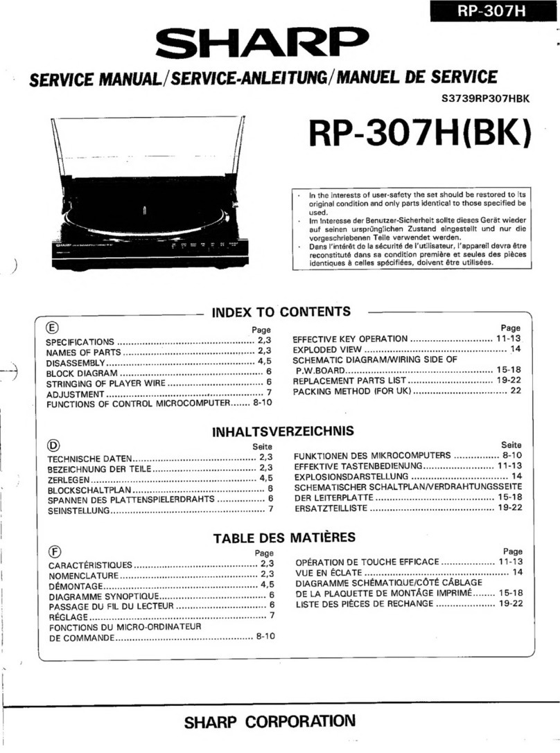
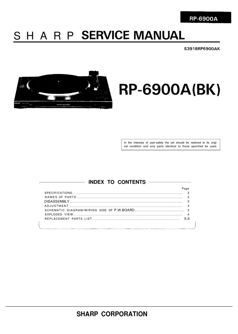
Sharp RP-LGOOA User manual

SHARI=
SERVICE
MANUAL
S7898RPL600AK
RP-LGOOA(BK)
in the Interests of user-safety the set should be restored to Its original
condition and
only
parts identical to those specified be used.
/
I
INDEX TO CONTENTS
Page
SPEClFlCATlONS
..................................................................2
NAMES
OF
PARTS
.................................................................
DISASSEMBLY
....................................................................2
ADJUSTMENT..
...................................................................
SCHEMATIC DIAGRAM/WIRING SIDE OF
P.W.BOARD
.................................
EXPLODED
VIEW
.................................................................
REPLACEMENT
PARTS
LIST
.....................................................
.6,7
SHARP CORPORATION

FOR A COMPLETE DESCRIPTION OF THE OPERATION OF THIS UNIT, PLEASE
REFER TO THE OPERATION MANUAL.
SPECIFICATIONS
Power source: DC 12V
Type: Belt drive, full automatic
Speed: 33-l
/3
and 45 rpm
Motor: DC motor
S/N ratio:
60
dB (DIN-B)
Wow and flutter:
to.2
oh
(DIN
45
500)
output:
3.0
mV
(I
kHz, 50
mm/sec.i
Frequency response: 20
-
20,000 Hz
Tracking force: 3
g
Tonearm:
Dynamic balanced straight
toneam
Cartridge: Magnetic type (CART-1
581
Replacement stylus: STY-
7
58
Dimensions: Width; 360 mm (14-l
/4”)
Height; 103 mm
14-l/8”)
Depth; 350 mm
(13-7/8”)
Weight:
2.5
kg (5.5
Ibs.)
NAMES
1. DC Supply Lead
2. 17 cm
(7”)
EP Record Adaptor
3. Turntable Platter and Mat
4. Dust Cover
5. Output Leads
6.
Cue Lever:
x
r
7.
Tonearm
8.
Cartridge
9. Record Speed Selector
10. Record Size Selector
11. Play Button:
4
12. Stop Button:
q
Specifications for this model are subject to change without
prior notice.
OF
PARTS
1
2
34
s
DISASSEMBLY
lb
1'1
Figure 2-1
Caution on Disassembly
Follow the below-mentioned notes when disassembling the
unit and reassembling it, to keep its safety and excellent
performance:
1.
Take Record out of the unit.
2. Before starting to disassemble the unit, be sure to remove
a DC supply plug from the
CD-LGOOA,
fix the
tonarm
to the
rest and remove the turntable.
3. Take off nylon bands or wire holders where they need
,be
removed when disassembling the unit. After servicing
the unit, be sure to rearrange the leads where they were
before
disassemblrng.
STEP
/
REMOVAL
/
PROCEDURE FIGURE
1
Dust
Cover
1.
Lift
it up to remove
-
2
Bottom
1. Screw
. . . . . . . . . . . .
. . . (A)
x
6
Plate
2,
HoOk
. . . . . . . . . . . . . . . . . .
(@x2
2-2
Hook
(Bb4
L4M
@
3xl2mm
Figure
2-2
-2-
ADJUSTMENT
As for adjusting method refer to the relevant explanation in
Service Manual “ADJUSTMENT PROCEDURES OF AUDIO
PRODUCTS”.
Connect the DC supply plug to the
CD-LGOOA
supply
+
12V
by
an external DC power supply.
. Lead-in
Test Record
Adjusting Point
Specified
value
SSR-4001
(Side 2)
After adjusting the lead-in position for 30 cm LP record, if
the 17 cm EP record lead-in position deviates, readjust with
the
revels
arm excentrc pin for 17 cm record. After the
adjustment, lock each one of
excentric
pins.
. Rotational Speed of Phono Motor
Jig
Strobo viewer
Adjusting Point
45 rpm:
VR102
33 rpm:
VRl
01
NOTE: Perform the 45 rpm speed adjustment first and them the
33 rpm speed adjustment.
Reverse Arm
0
0
/co
/co
Bottom SideBottom Side
clcl
LL
L-JL-J
U
Front SideFront Side
EP17cm
VR102
45rpm
VRlOl
33rpm
With turntable removed
With bottom plate removed
Figure 3-l ADJUSTMENT POINTS
-3-

CARTRiDGE(54-4)
0
LJTPUT
PLUG<591
BLACK
DC POWER
SUPPLY
PLUG(60)
MOTOR<651
I
RED
1~~~~
I
SPEED
33rpm
i__________----_-_------------------------~
Figure 4-l SCHEMATIC DIAGRAM
Fl
WHITE
mL
7
Co-LGOOA
Only
tal
CARTRIDGE
DC
POWER
,54-41
SUPPLY
PLUG
,601
MOTOR
(651
Figure
4-2
WIRING SIDE OF
P.W.BOARD
NOTES ON SCHEMATIC DIAGRAM
. Resistor:
To differentiate the units of resistors, such symbol as
K
is
used: the symbol
K
means 1000 ohm and the resistor
without any symbol is ohm-type resistor.
. Capacitor:
To indicate the unit of capacitor, a symbol
P
is used: this
symbol
P
means micro-micro-farad and the unit of the
capacitor without such a symbol is microfarad. As to elec-
trolytic capacitor, the expression “capacitance/withstand
voltage” is used.
. Schematic diagram and Wiring Side of
P.W.Board
for this
model are subject to change for improvement without prior
notice.
REF. NO.
DISCRIPTION
SW101 SPEED Selector
SW1
02 Start
SW1
03
Arm
POSITION
33
-
45
ON
-
OFF
-
ON
-
OFF
-4-

I
t
t
1I
2
I
3
I
4
I
5
I
6
Figure 5 CABINET EXPLODED VIEW
-5-

REPLACEMENT PARTS LIST
“HOW TO ORDER REPLACEMENT PARTS”
To
have your order filled promptly and correctly, please furnish the following information.
1. MODEL NUMBER 2. REF. NO.
3. PART NO. 4. DESCRIPTION
REF.NO.
PART NO.
DESCRIPTION CODE REF.NO.
PART NO. DESCRIPTION
CONTROLS
VRlOl
VR102
99H42222021200
Semi-VR,30
kohms
63)
f33
rpml
99H42222010000
Semi-VR,5
kohms
(B]]45
rpml
AC
AC
CAPACITORS
-Cl02
99HlH104JBCALC
0.1
pF,fjOV,Ceramic
AC
Cl03
99HlC33
OMDDALC 33
/zF,16V,Electrolytic
AB
RESISTORS
-(Unless otherwise specfifed, resistors are
?5%,carbon
type.)
RlOl
R10.2
RI03
VRD-ST2EE133J
13
kohms,1/4W
VRD-STZCD203J
20
kohms,l/6W
VRD-ST2EElOPJ
1
kohm,l/4W
OTHER CIRCUITRY PARTS
AA
AA
AA
SW101
99H42319787300
Switch.Push
Tvpe
fSPeed1 A
E
SW102
99HF49384000
SwitchSlide
Type . AD
-SW103
99H42319785600
Switch,Siide
TypeAC
8
9
10
11
12
13
14
15
16
17
18
19
20
CABINET PARTS
99HD10091040
Cabinet AX
99HD49725000
Cushion AC
99HD49216010
Button,Play/Stop
AC
99H28559140000
Spring,Play/Stop
AA
99HD49217010
ButtonSpeed
AC
99HD49219000
Knob,Record Size AC
99H27419986000
Select Lever AC
99HD49616000
Pin Cushion AB
99HH32247010
Bottom Plate AK
99HD21110020
Dust Cover AT
99H22904134010
Cushion,Cabinet
AB
99HK49326000
Hinge Dust Cover AG
99HH49235000
Felt AA
99H25202118000
Rubber
CushionMotor
AB
99H24110115000
Main Gear AG
99H24122127000
Clutch Guide AC
99H24122121000
Clutch Plate AC
99H28559063000
Spring,Cam
Driver AA
99H06028110000
Cam Driver AD
99HC49193000
Operation Chassis AG
21
99HE49252000
Spring,Operation
Chassis
22
99H07419432000
Lever,Size
23
99H24106270020
Screw,Support
24
99HB49515000
Shaft,Sensor
25
99H24120196000
Lever
26
99H25101337010
Spring,Sensor
Arm
27
99HD49519000
Plate,Tonearm
28
99HD49521000
Plate,Tonearm
Driver
29
99HE49540000
Spring,Tonearm
Driver
30
99HC49517000
Sensor Arm
31
99HD49220000
Switch Plate
32
99HB49320000
Cam
33
99H24459398000
Rubber Cushion
34
99H25739077000
Support
35
99H27419987000
LeverStart
36
99H27439495000
Return Arm
37
99H27439497000
Trigger Arm
38
99H27439498000
Lead In Arm
39
99H27519765000
Shaft,Sensor
40
99H28519600000
Spring,Trigger
Arm
41
99HE49701000
Rod,Play
42
99HE49702000
RodStop
43
99H28529294000
RodSize
Selector
44
99H28529297000
SpringStart
Lever
45
99H28529311000
RodSupport
46
99H28529295000
Spring,Size
Lever
47
99H25103100000
Plate Spring
48
99H27419988000
Cueing Lever
49
99HD49204010
Arm Lifter
50
9
9H2
8 5 5 9 13 9 0 0 0
Spring,Arm
Lifter
51
99H25229010020
Turntable
52
99HD49529000
Belt
53
99HC49682000
Shaft
r
CODE
AB
AD
AB
AB
AC
AA
AF
AC
AB
AF
AC
AD
AB
AB
AC
AC
AB
AC
AB
AB
AC
AC
AC
AB
AA
AB
AA
AB
AC
AA
AW
AG
AK
BA
54
54-l
99HC31916500
Tonearm
Ass’y
Tonearm
54-2
54-3
54-4
55
56
57
58
59
60
61
62
63
64
65
67
68
70
71
200
201
202
203
205
PNDLDOlO3AFZZ
Stylus
(STY-158)
99H26459009000
Stylus Cover
RCTRE5106AFZZ
Cartridge
99HB49205000
Spacer,Tonearm
99H24203202020
Washer
99H24202116000
Nut
99HSCRET50SE
Stop Ring
99HF32210000
output Plug
99HF32243000
DC Power Supply Plug
99HF49752000
Lug with
Wtre
99H23608165000
Bracket,Cord
99H4429005000
Mat,Turntable
99HD49759000
EP Adaptor
99HC49640000
Motor Ass’y
99H23608141000
Nylon Band
99HA49525000
Cramp Shield
99HK49818020
Label Specifications
99HH49812020
Label [CD-LGOOA Only]
99HFBA30120SG
Screw,$3Xl2mm
99H24201252050
Screw,
d3X
1Omm
99H24201283000
Screw,d3X
1Omm
99HR49319000
Screw,
d
3
X
12mm
99H24201136000
Screw,Motor
-6-
-
AW
AC
AX
AD
AA
AA
AA
AK
AK
AC
AA
AL
AC
AT
AA
AC
AC
AC
AA
AB
AB
AC
AB

REF.NO.
PART NO. DESCRIPTION
CODE
206
99HFBDN208ROSM
Screw,d2X8mm
AA
207
99HZ458ROOR3SE
Washer,&4.5Xd8X0.3mm
A A
208
99HSN2H3N40SE
Nut,$4mm AA
209
99HZ321301ROSE
Washer,~3.2XQ13Xlmm
A A
210
99HZ421000R5SE
Washer,b4.2X$lOXO.Smm
A A
211
99H24569099000
WasherAA
212
99H24203197030
Stop Washer AA
214
99HZ321000R5SE
Washer,~J.PX~lOX0.5mm
A A
215
99HSCRET20SE
Stop Ring AA
216
99HSCRET30SE
Stop Ring AA
217
99H24220105020
Stop Ring AA
218
99HSN2H2N26SE
Nut,d2.6mm AA
219
99HSVS2L26SE
Spring,Washer,&2.6mm A A
220
99HF266R50R5SE
Washer,$2.6>:46.5X0.5mm
A A
ACCESSORIES/PACKING PARTS
PWB-A
99HD21125000
Packing Add. Front AG
99HD21126000
Packing Add. Rear AG
99HD49706000
Turntable Pad AG
99HH32249040
Packing Case AM
99H49679000
Sheet,Turntable
AB
99H62519164900
Cushion Mat AB
99H627
19
1040
10
Polyethylen
Bag,Operation
A A
Manual
99H6321900
100 0 Polyethylen
Bag,Unit
AC
P.W.B. ASSEMBLY
(Not Replacement
Item)
99HC49532050
Main
-
-7-

SHARF’
1
A8807-805NS
t
IS.
J
j
Writer and Editor: Quality
&
Reliability Control Center of Audio Systems Group,
Sharp
Corp.
Printed in Japan
SA
This manual suits for next models
1
Table of contents
Other Sharp Turntable manuals

Sharp
Sharp RP-20 User manual

Sharp
Sharp OPTONICA RP-9100H User manual

Sharp
Sharp RP-117 User manual

Sharp
Sharp DX-SX1H User manual

Sharp
Sharp RP-116H User manual

Sharp
Sharp RP-107H User manual

Sharp
Sharp RP-6900A User manual

Sharp
Sharp RP-4500A User manual

Sharp
Sharp RP-32 Series User manual

Sharp
Sharp RP-205H User manual