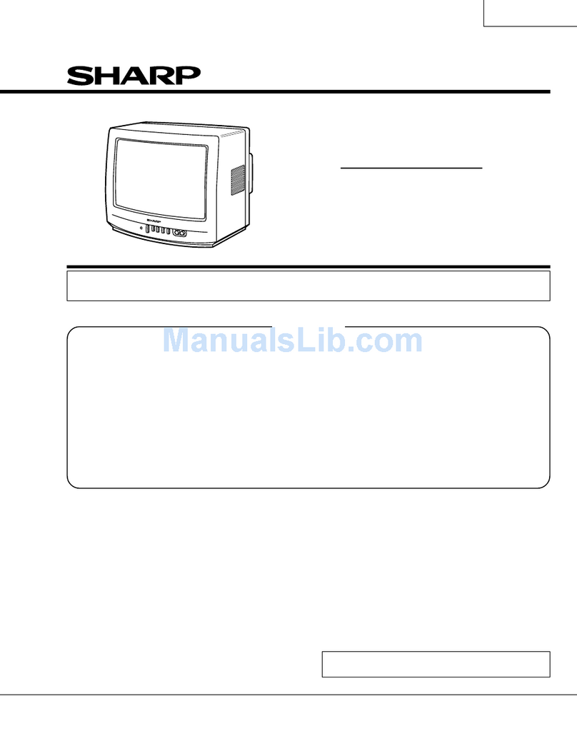
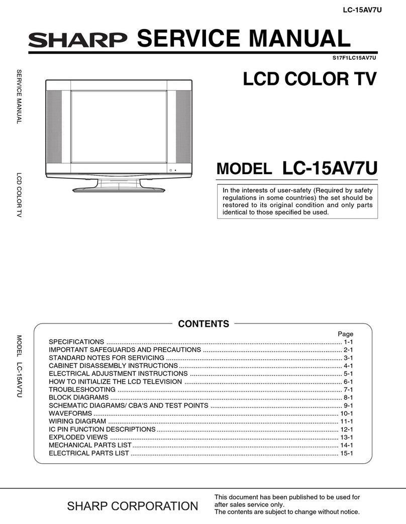
Sharp 29F-PE550 User manual

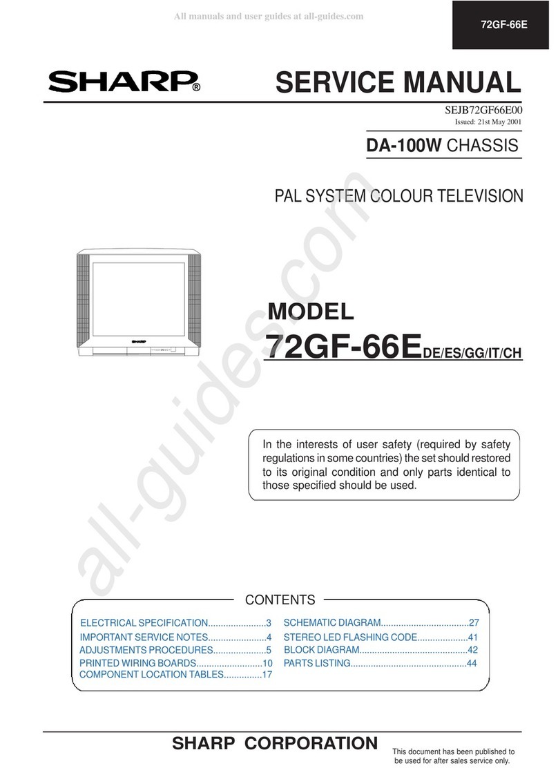
29F-PE550 / 29F-PD570
SERVICE MANUAL
COLOUR TELEVISION
Chassis No. GB-7
CONTENTS
WARNING
The chassis in this receiver is partially hot. Use an isolation transformer between the line cord plug and
power receptacle, when servicing this chassis. To prevent electric shock, do not remove cover. No user -
serviceable parts inside. Refer servicing to qualified service personnel.
World Multi 21 System
100-CH Program Memory
AV Mode (Movie/Music/News)
CATV Hyper Band Ready
Blue/White Stretch Circuit
Picture Noise Reduction
White Temp. Select
Gamma Correction
Multi Language OSD (English / Thai)
CHAPTER 1. SPECIFICATIONS
[1] SPECIFICATIONS.......................................1-1
CHAPTER 2. IMPORTANT SERVICE NOTES
[1] IMPORTANT SERVICE NOTE................... 2-1
CHAPTER 3. ADJUSTMENT PRECAUTIONS
[1] ADJUSTMENT PRECAUTIONS .................3-1
[2] ADJUSTMENT ............................................3-26
CHAPTER 4. TROUBLE SHOOTING FLOWCHART
[1] TROUBLE SHOOTING FLOWCHART........4-1
CHAPTER 5. SOLID STATE DEVICE BASE DIAGRAM
[1] SOLID STATE DEVICE BASE DIAGRAM...5-1
CHAPTER 6. CHASSIS LAYOUT
[1] CHASSIS LAYOUT......................................6-1
CHAPTER 8. DESCRIPTION OF SCHEMATIC DIA-
GRAM
[1] DESCRIPTION OF SCHEMATIC DIAGRAM 8-1
CHAPTER 9. WAVEFORM
[1] WAVEFORM............................................... 9-1
CHAPTER 10. SCHEMATIC DIAGRAM
[1] SCHEMATIC DIAGRAM : MAIN UNIT.........10-1
[2] SCHEMATIC DIAGRAM : CRT UNIT ..........10-3
CHAPTER 11. PRINTED WIRING BOARD ASSEMBLIES
[1] PWB-A : MAIN UNIT....................................11-1
[2] PWB-B : CRT UNIT .....................................11-3
In the interests of user safety (Required by safety regulations in some countries) the set should be restored to its original
condition and only parts indentical to those specified should be used.
Off Timer
Rear AV-IN 1, AV Output (Monitor Out),
and Front AV-IN 2 (Auto Select)
Headphone (Front)
Component & Audio Input Terminal
Nicam & A2 Stereo
Child Lock
Surround
Equalizer
Hotel Mode AVL
Parts Guide
1st Edit ion
SHARP MANUFACTURING (THAILAND) CO.,LTD
...
CHAPTER 7. BLOCK DIAGRAM
[1] BLOCK DIAGRAM : MAIN UNIT .................7-1
29F-PE550
29F-PD570
29F-PD570 29F-PE550
Loundness
AFT

29F-PE550 / 29F-PD570
1 - 1
CHAPTER 1.
SPECIFICATIONS
[1] SPECIFICA
TIONS
SPECIFICATIONS
Focus..................................................................... Bi-Potential, Uni-Potential Electrostatic
Sweep Deflection ................................................................................................... Magnetic
Intermediate Frequencies
Picture IF Carrier ................................................................................................ 38.9MHz
Sound IF Carrier
6.5MHz ............................................................................................................ 32.4MHz
6.0MHz ............................................................................................................ 32.9MHz
5.5MHz ............................................................................................................ 33.4MHz
Colour Sub-Carrier
PAL................................................................................................................ 34.47MHz
SECAM .............................................................................................. 34.494/34.65MHz
Power Input ................................................................................... 110 ~ 240V AC 50/60 Hz
Power Consumption ..................................................................................................... 123W
Audio Power Output Rating ........................................................................ 7.5 W x 2 (Rated)
Speaker
Size.......................................................................... 29F-PE550 : 8 cm x 12 cm (oval) x 2
Aerial Input Impedance
VHF/UHF ......................................................................................... 75 ohms Unbalanced
Receiving Channels
PAL-B/G, SECAM-B/G
VHF ................................................................................................................ E2 thru E12
UHF .............................................................................................................. E21 thru E69
CATV ......................................................................................... X thru Z + 2, S1 thru S41
PAL-D/K, SECAM-D/K, K1
VHF .......................................................................................... R1 thru R12, C1 thru C12
UHF .......................................................................................... 21 thru 69, C13 thru C57
PAL-I, SECAM-I
VHF .............................................................................................. (IRELAND): B thru J
UHF ............................................................................................ (U.K., H.K.): 21 thru 69
Receiving Frequency................................................................ 44.25 MHz thru 863.25 MHz
Dimensions............................................................................... 29F-PE550 : Width: 810mm
Height: 618mm
Depth: 531.5mm
Weight(approx): 42 kg
Cabinet material .................................................................................................. All Plastics
Specifications are subject to change without prior notice.
Convergence ............................................................................... Self Convergence System
5.74MHz ......................................................................................................... 33.16MHz
4.5MHz ............................................................................................................ 34.4MHz
NTSC .............................................................................................................. 35.32MHz
NTSC-M
VHF ........................................................................... (U.S.): 2 thru 13, (Japan): 1 thru 12
UHF ....................................................................... (U.S.): 14 thru 69, (Japan): 13 thru 62
CATV ....................................... (U.S.): A-6 thur A-1, A thru W+29 (Japan): C13 thru C63
29F-PD570 : Width: 810mm
Height: 618mm
Depth: 516.5mm
Weight(approx): 41 kg
29F-PD570 : 8 cm Round x 2

29F-PE550 / 29F-PD570
2 - 1
CHAPTER 2. IMPORTANT SERVICE NOTES
[1] IMPORTANT SERVICE NOTE
IMPORTANT SERVICE NOTES
Maintenance and repairing of this receiver should be done by
qualified service personnel only.
SERVICE OF HIGH VOLTAGE SYSTEM AND
PICTURE TUBE
When servicing the high voltage system, remove static charge from it by
connecting a 10K ohm resistor in series with an insulated wire (such as a test
probe) between picture tube dag and 2nd anode lead. (AC line cord should
be disconnected from AC outlet.)
1. Picture tube in this receiver employs integral implosion protection.
2. Replace with the same type number of picture tube for continued safety.
3. Do not lift picture tube by the neck.
4. Handle the picture tube only when wearing shatterproof goggles and after discharging
the high voltage completely.
X-RAY
This receiver is designed so that any X-Ray radiation is kept to an absolute
minimum. Since certain malfunctions or servicing may produce potentially
hazardous radiation with prolonged exposure at close range, the following
precautions should be observed:
1. When repairing the circuit, please make sure do not increase the high voltage of the set
to more then 34.0kV (at beam 0 A).
2. To keep the set in a normal operation, please make sure it's function at 30.0kV 1.5kV
(at beam 1700 A). The set has been factory - adjusted to the above-mentioned high voltage.
*If there is a possibility that the high voltage fluctuates as a result of the repaires,
never forget to check for such high voltage after the work.
3. Do not substitute a picture tube with unauthorized types and/or brands which may cause
excessive X-ray radiation.
BEFORE RETURNING THE RECEIVER
Before returning the receiver to the user, perform the following safety checks.
1. Inspect all lead dress to make certain that leads are not pinched or that hardware is not
lodged between the chassis and other metal parts in the receiver.
2. Inspect all protective devices such as non-metal control knobs, insulating fishpapers,
cabinet backs, adjustment and compartment covers or shields, isolation resistor- ca-
pacity networks, mechanical insulators etc.

29F-PE550 / 29F-PD570
ADJUSTMENT PRECAUTIONS
This model's setting are adjusted in two different ways: through the I2C bus control and in the
conventional analog manner. The adjustments via the I2C bus control include preset-only items and
variable data.
1. Setting the service mode by the microprocessor.
(1) Press and hold the local key "VOL DOWN" & "CH UP" when power on the main switch,
TV will enter into the SERVICE MODE. (The initial value of EEPROM are automatically
preset when new EEPROM is used)
(2) Press the CH DOWN / UP key on the remote controller to select the setting items
one by one.
(3) Using the VOLUME UP/ DOWN key on the remote controller, the data can be modified.
(4) When press the local key "VOL DOWN" & "CH UP" at the same time,
it will be released from the service mode.
2. Factory Presetting.
(1) Press remote controller key of code "ED" for 4 seconds, the initial values are
automatically preset.
(2) The initial data are preset as listed in page 3-4 and 3-6.
(3) Make sure whether the data need to modify or not (Initial data).
Note: Once the chassis has been assembly together and in ready condition, please make
sure it's go through initialize process (see sect 2 above)
Precaution: If haven't done this initialization, malfunction might be happen.
3-1

29F-PE550 / 29F-PD570
1) In the Service Mode, key is use to select the mode in the following order.
SUB : ISSUE OF ADJUSTMENT METHOD
WE ISSUE THE ADJUSTMENT MANUAL AS FOLLOWS.
MODEL: 29F-PE250I (
A
3WC9E25IL)
ADJUSTMENT MODE
RF AGC 50Hz / 60Hz
GEOMETRIC ADJ
CUT OFF/
WHITE BALANCE ADJ
PICTURE/SOUND
SUB ADJ
3-2
This manual suits for next models
1
Table of contents
Other Sharp TV manuals

Sharp
Sharp CX68RF5 User manual

Sharp
Sharp Aquas LC-52LE920UN User manual

Sharp
Sharp 21LF-90C User manual

Sharp
Sharp LC-22DV510E User manual

Sharp
Sharp 70GS-65S User manual

Sharp
Sharp 21HF2-SS User manual

Sharp
Sharp 21LT-45SES User manual

Sharp
Sharp 50DJ1K User manual

Sharp
Sharp 27F641 User manual

Sharp
Sharp 70GS-66E User manual

Sharp
Sharp LC13-B2E User manual

Sharp
Sharp 25N M180 User manual

Sharp
Sharp 32BB2I Technical manual

Sharp
Sharp 26SL40 User manual

Sharp
Sharp LC-32BD1 User manual

Sharp
Sharp 21J-FG1RU User manual

Sharp
Sharp 21AG1-SMK3 User manual

Sharp
Sharp AQUOS LC-32CHG6001E User manual

Sharp
Sharp 21E-FG1S User manual

Sharp
Sharp 28JS-74SS User manual