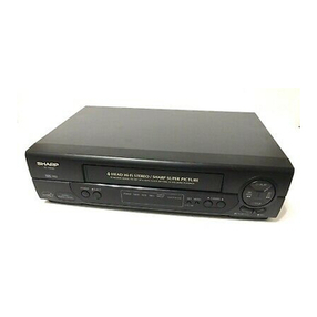
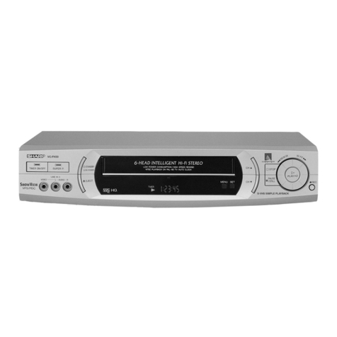
Sharp VC-780E User manual

VC-790ET
SHARP
SERVICE
MANUAL
|
S29X6VC-780E/
|
VIDEO
CASSETTE
RECORDER
VC-780E
moves
VC-790ET
In
the
interests
of
user-safety
(Required
by
safety
regulations
in
some
countries)
the
set
should
be
restored
to
its
original
condition
and
only
parts
identical
to
those
specified
should
be
used.
CONTENTS
SPECIFICATIONS
DISASSEMBLY
AND
REASSEMBLY
LOCATION
OF
MECHANICAL
PARTS
ADJUSTMENT,
REPLACEMENT,
ASSEMBLING
AND
|
TOOLS
NECESSARY
FOR
MECHANICAL
ADJUSTMENT
ADJUSTMENT
OF
ELECTRICAL
CIRCUITRY
TROUBLESHOOTING
GUIDE
OTHER
TROUBLESHOOTING
GUIDE
WAVE
FORMS
OVERALL
SEHEMATIC
DIAGRAM
SCHEMATIC
DIAGRAMS
WIRING
SIDE
PWBs
REPLACEMENT
PARTS
LIST
EXPLODE
VIEWS
PACKING
OF
THE
SET
femmes
ge
ees,
Aes
oie
a
wage
faery
SHARP
CORPORATION
a

=
in
VC-790ET
Format:
Video
recording
system:
Video
signal:
PAL:
PAL:
PAL:
SECAM:
SECAM:
SECAM:
NTSC:
.
NTSC:
Recording
playing
time:
Tape
width:
Tape
speed:
Antenna:
-Receiving
channel:
RF
converter
output
signal:
Power
requirement:
Power
consumption:
Operating
temperture:
Storage
temperature:
Weight:
Dimensions:
VIDEO
Input:
Output:
AUDIO
Input:
Output:
AUDIO
Input:
Output:
Accessories
included:
Note:
SPECIFICATIONS
VHS
standard
Rotary
two-head
helical
scan
system
with
slant
double-azimuth
combination
video
head.
PAL
System-B/G
(
P.B/REC)
PAL
System-|
(P.B/REC)
PAL
System-D
(P.B/REC)
MESECAM
System
(P.B/REC)
SECAM
System-B/G
(
P.B/REC
)
SECAM
System-D/K
(
P.B/REC
)
NTSC
4.43
(
P.B/REC)
_
NTSC
3.58
(
P.B/REC)
240
min
max.with
SHARP
E-240
tape
(PAL/MESECAM/SECAM
in
SP
mode)
8
hours
max.
with
SHARP
E-240
tape
(PAL/MESECAM/SECAM
in
LP
mode)
160
min
max.with
SHARP
T-160
tape
(NTSC
in
SP
mode)
320
min
max.with
SHARP
T-160
tape
(NTSC
in
LP
mode)
8
hours
max.
with
SHARP
T-160
tape
(NTSC
in
EP
mode)
12.7
mm
23.39
mmisec.
(PALin
SP
mode)
33.35mm/msec.
(NTSC
in
SP
mode)
11.7mmisec.
(PALinLP
mode)
16.68mmi/sec.
(NTSC
in
LP
made)
11.12
mm/sec.
(NTSC
in
EP
made)
75
ohm
unbalanced
VHF
E2~
E12,
(44.25MHz
~294.25MHz)
UHF
E21~
E69,
(471.25MHz
~885.25MHz)
UHF
Channel!
E30
~
£39
(adjustable).
Preset
to
Channel
E36
UHF
Channel
US26~US38(adjustable).
Preset
to
Channe!
US34
UHF
Channel
J25~J37
(adjustable).
Preset
to
Channel
J33
AC
100~240V,
AUTO
50/60
Hz
Approx.
23W
(at
AC
220V
50Hz)
5°C
to
40°C
-
20°C
to
55°C
5.8kg
430
mm
(W)
x
350
mm
(D)
x
89mm
(H)
1.0
Vp-p,
75
ohm
1.0
Vp-p,
75
ohm
OdB
=
0.775
Vrms
Line: -8dB,
more
than
50k
ohm
at
RCA
terminal
Line:
-
5
dB,
less
than
1k
ohm
0d8
=
0.775
Vrms
Line:
-
3.8
dB,
more
than
50k
ohm
\
at
Pin
21
terminal
Line:
-
3.8
dB,
less
than
1k
ohm
Antenna
75
ohm
coaxial
connector
cable
(plug
provided)
Operation
Manual
infrared
Remote
contro!
As
part
of
our
policy
of
continuous
improvement,
we
reserve
the
right
to
alter
design
and
specifications
without
notice.
The
antenna
must
correspond
to
the
new
standard
DIN
45325
(IEC
169
-
2)
for
combined
UHF/VHF
antenna
with
75
ohm
connector.

a
ye
ee
rs
nnn
a
Soe
PS
Po
DISASSEMBLY
AND
REASSEMBLY
Remove
the
four
upper
cabinet
fastening
screws
q).
Remove
the
six
bottom
pane!
fastening
screws
@).
Remove
the
one
front
panel
fastening
screw
(3).
Release
the
three
clips
(4)
and
remove
the
front
panel.
Remove
the
two
antenna
terminal
cover
fastening
screws
on
the
tow
push
rivets
which
fasten
the
syscon
servo
unit
and
the
angle.
Remove
the
four
syscon
servo
unit
fastening
screws
(7)
F
Remove
the
Y/C
PWB
holder
@).
9,
Remove
the
two
main
PWB
fastening
screws
(9)
‘
.
Remove
the
two
head
amp
PWB
fastening
screws
;
.
Remove
the
three
power
unit
fastening
screws
.
Remove
the
four
machanism
chassis
fastening
screws
Release
the
timer
PWB
43)
fastening
clips.
Release
the
operation
PWB
fastening
clips.
Vi-
#00)
VC-790ET
a

LOCATION.
LIST
OF
MECHANICAL
PARTS
|
A/C
head
arm
-
os
Half-loading
lever
spring
.
inch
roller
lever
ass’y
elay
shifter
lever
etaining
guide
|
Capstan
0.D.motor
Main
take-up
brake
lever
eee
ee:
Cassette
LED
-
Reverse
guide
spring
@
nghrl
sere
bee
aeetcitl
7
Idler
gear
ass
y
Take-up
reel
disk
.
Reverse
guide
|Video
search
brake
lever
7
|Take-up
pole
base
slider
Tension
spring
hook
plate
-
.
—
LL
Half-loading
lever
Reel
pulley
Reel
sensor
PWB
Brake
solenoid
Shifter
spring
Shifter
spring
cover
.
ut
Connector
Tension
band
ass’y
17
|
Auxiliary
fast
forward
brake
lever
Reverse
guide
spring
Reel
belt
Loading
relay
gear
>
an
:
WwW
Supply
pole
base
ass’y
;
5
wi
nn
Slow
brake
fever
ee
X-position
adjusting
nut
Half-loading
reciprocating
spring
Half-loading
reciprocating
lever
Slow
brake
spring
ive)
Relay
gear
drive
lever
~
Take-up
loading
gear
NS
Take-up
loading
armass'y
—.
Drum
D.D.
motorass'y
__
Supply
loading
gear
:
Supply
loading
arm
ass‘y
|
Loading
reciprocating
spring
Supply
pole
base
slider
oS
67
|
Reel
block
chassis
wal
uw
~
Auxiliary
fast
forward
brake
spring
Full
flat
cable
holder
ull
flat
cable(
Drum
D.D.
motor)
tat
mw
Wi
wi
Ww
as
mT
NO
eed
Ww
“wan
>
0
3.
|
Half-loading
drive
lever
AJ
—-
4
}jLoading
block
ass’y
Reel
sensor
on
Loading
motor
ain
brake
spring
Master
cam
ew
sensor
=
w
|
w
sls
BE
fj
Ww
Oo
>
oy

ea
a
”
e@
TOP
VIEW
™A®HO@OOMOMOPOOC
®@
BOTTOM
VIEW
[6—6MO®
O©®@
OF
@™O®™
EO
LOCATION
OF
MECHANICAL
PARTS
C5)
@6) G7) 28)
@2)
SOS!)
G2)
G3
3
65)
\
bod
a
ats
(‘S
\_\
7)
fe
TAWA,
daa
TT
oe
ou
7
°
porn
AE
‘
SE
ie
ry
ma
:
|
A
alan
il
a:
69)
GO
60)
6!)
HQ0OOOM
|—6
OO
@@OOCO@O@OOAMO®D
®
@®@@@O®
@
Vo-/#0U
Ad
Oe
2-18)
=a
I

|
VC-790ET
ADJUSTMENT,
REPLACEMENT,
ASSEMBLY
AND
CLEANING
OF
MECHANICAL
UNITS
Here
we
will
describe
a
relatively
simple
service
work
We
are
sure
that
the
easy-to-handle
tools
listed
in
the
field,
not
referring
to
the
more
complicated
below
would
be
more
than
handy
for
periodical
repairs
which
would
require
the
use
of
special
maintenance
to
keep
the
machine
in,.its,original
equipment
and
tools
(drum
assembly
or
re-
efficient
condition.
placement,
for
example).
TOOLS
NECESSARY
FOR
ADJUSTING
THE
MECHANICAL
UNITS
The
following
tools
are
required
for
proper
service
and
satisfactory
repair.
[na[
item
|
ranno.
fou]
configuration
Reel
Disk
Height
AdjustingJig.”
Ss:
Ss
SiGRHOOO2
?
JiGACH-F18
Torque
Gauge
(90g)
JiGTGOOSO
Torque
Gauge
(1.2
kg)
JiGTG1200
5
Gauge
Head
Cassette
Torque
Meter
ne
[we
wm
[|
SA
ae
Hex
Wrench
(1.5
a
VROCPSV
These
Jigs
are
used
for
checking
and
adjusting
the
reel
disk
height.
This
Jig
is
used
for
settimg
the
A/C
ASC
Head
Tilt
Adjusting
Jig
eine
ead
tilt.
—
These
Jigs
are
used
for
checking
and
adjusting
the
torque
of
take-up
and
supply
reel
disks.
This
cassette
torque
meteriis
Used
for
checking
and
adjusting
the
torque
of
take-up
and
supply
reel
and
for
measuring
tape
back
tension.
There
are
two
Gauges
used
for
the
tension
méasurements,
300
g
and
2.0
kg.
6
7
These
Jigs
are
used
for
loosening
or
tightening
special
Hexagon
type
screws.
This
tape
ts
especially
used
for
electrical
fine
adjustment.
Alignment
Tape
(PAL}
This
is
used
for
replacement
of
the
VCR's
upper
drum.
Drum
Replacing
Jig
JiGDT-0001
This
Jig
is
used
for
the
tension
gauge.
Rotary
Transtormer
Clearance
Adjusting
Jig.
JiGADP003
BK
GN
SB
Tension
Gauge
Adapter

¥,
VC-790ET
2]
aw
|
JIGDRIVER-6
a
Torque
Driver
JiGTD1200
JIGDRIVER1
10-7
This
Screwdriver
is
used
for
adjusting
the
guide
roller
height
and
X-position.
Special
Bladed
Screwdriver
JiGDRIVERH-4
This
Jig
is
used
for
adjusting
the
tension
band
and
tension
plate.
Tension
Band
and
Plate
Adjusting
Jig
This
is
used
to
screw
down
resin-
made
parts:
the
specified
torque
is
5
kg.
This
Jig
is
used
for
height
adjustment
of
the
A/C
head.
Box
Driver
This
Jig
is
used
for
height
adjustment
of
the
retaining
guide.
JiGDRIVER1
10-4
”
a
JiGRVGH-F1i8
=|
BU
ar
Current
JiGMA0001
contains
Master
Plane
(JiGMP0001)
and
Disk
Height
Adjusting
Jig
ViGRHO001).
Even
though
new
Disk
Height
Adjusting
Jig
UiGRHO002)
covers
greater
height,
This
Jig
is
used
for
height
Retaining
Guide
Height
Adjusting
Jig
sdjustient
Gt
the
retaining
guide
This
Jig
is
used
for
height
adjustment
of
the
reverse
guide.
Reverse
Guide
Height
Adjusting
Jig
this
new
Jig
JiGRHO002)
can
be
used
for
current
JiGRHO001,
but
current
Jig
(JiGRHO001)
cannot
be
used
as
JiGHROO02.Master
Plane
(JiGMPO001)can
be
used
with
JiGRHO001
and
JiGRHOOO2
as
well.

Vier
FOUL
VC-790EF
:
MECHANICAL
PARTS
REQUIRING
PERIODICAL
INSPECTION
~
Use
the
following
table‘as
a
guide
to
maintain
the
mechanical
parts
in-good
operating
condition.
ee
=
nt
Remarks
Abnormal
rotation
or
significant
vibration
requires
replacement.
-.
Clean
with pure
high
quality
—-
~-
isopropy!
alcohol.
conan
tetetete
Cc
i
ee
ROS
Ee
oe
Clean
tape
contact
area
with
the
PS
specified
cleaning
liquid.
Clean
tape
contact
area
with
the
specified
cleaning
liquid.
Clean
rubber
and
rubber
contact
area
with
the
specified
cleaning
NOTE:
©:
Part
replacement.
OC):
Cleaning
(For
cleaning,
use
a
lint-free
cloth
dampened
with
pure
isopropyl
alcohol).
A:
Oil
refilling
(The
indicated
point
should
be
lubricated
with
high
quality
spindle
oil
every
1000
hrs).
This
model
has
no
adjusting
parts
for
torques,
tension,
etc.
If
the
reading
is
outside
the
specified
range,
clean
or
replace
the
part.

REMOVAL
AND
REASSEMBLY
OF
CASSETTE
HOUSING
CONTROL
ASSEMBLY
Notes:
1.
During
removal
and
reassembly,
be
careful
not
to
strike
the
nearby
guide
pin,
drum,
etc.
2:
Before
removal
or
reassembly,
be
sure
to
unplug
the
recorder
from
the
AC
outlet.
3.
When
removing
and
attaching
the
cassette
loading
belt,
be
careful
to
keep
it
free
from
grease.
Removal
_
Put
the
unit
in
the
cassette
eject
position.
_
Remove
the
cassette
loading
belt
©.
Disconnect
the
FFC
(Full
Flat
Cable)
@
at
the
right
side
of
the
cassette
housing
control
assembly.
Note:
Be
careful!
not
to
break
the
FFC.
4.
Remove
the
two
cassette
housing
installation
screws.
_
Move
the
cassette
housing
control
assembly
(Fig.
1-1)
in
the
direction
of
arrow
=>
®,
and
pull
it
out
straight
upward.
wn—
@
wi
e®
Reassembly
1.
Insert
the
tabs
of
the
cassette
housing
contro!
assembly
into
the
mechanism
chassis,
move
it
in
the
direction
of
arrow
>
@,
and
secure
tem-
porarily.
Check
to
see
if
the
cassette
housing
control
assembly
is
in
the
correct
position,
and
then
tighten
the
two
screws
(XHPS330PO06WSO)
.
_
Attach
the
cassette
loading
belt
©.
|
Connect
the
FFC
@
at
the
right
side
of
the
cassette
housing
control
assembly.
Ww
A
(D
Cassette
loading
belt
@
FFC
ball
1
—
bed
For
~
HM
—
1
=f
HELE
+
i
Insert
the
tabs
of
the
cassette
housing
into
the
GL,
mechanism
chassis.
Figure
1-1.
(Full
flat
cable}
V¥U-
760
VC-790ET
REPLACEMENT
OF
WORM
WHEEL
ASSEMBLY
e
Removal
(Fig.
1
-
2)
1.
Unsolder
the
cassette
switch
connector
from
the
start
sensor
PWB
@
2?
Release
the
two
catches
@on
the
cassette
housing
frame
(R),
and
remove
the
PWB.
3.
Unscrew
one
B
tight
screw
@
to
detach
the
worm
bracket
@.
Note:
The
bearing
@
can
come
off
position
too.
So
be
careful
not
to
let
the
bearing
fall.
4.
Remove
the
worm
shaft
assembly
©,
pulley
©
and
cassette
loading
belt
@
all
from
the
cassette
housing
frame
(R).
5.
Finally
pull
the
worm
wheel
assembly
out
of
the
boss
of
the
cassette
housing
frame
(R).
e
Reassembly
(Fig.
1-2)
1.
Turn
the
phase
gear
@
clockwise
until
the
slider
comes
to
a
halt
in
the
cassette
insertion
direction.
2.
Set
up
the
worm
wheel
gear
assembly
onto
the
boss
on
the
cassette
housing
frame
(R),
matching
the
mark
©
on
the
phase
gear
@
with
the
mark
®
on
the
worm
wheel
gear.
Note:
Make
sure
that
the
slider
pin
is
in
the
groove
of
the
drive
gear
arm.
3.
Install!
the
pulley
©
and
apply
the
cassette
loading
belt
@
both
on
the
worm
shaft
assembly
©.
Couple
the
clutch
@
to
the
clutch
lever
©.
|
And
mount
them
together
in
the
cassette
housing
frame
(R)
.
4.
Attach
the
worm
bracket
@
to
the
worm
shaft
assembly
@.
Place
them
onto
the
boss
on the
cassette
housing
frame
(R).
5.
Tighten
one
B
tight
screw
@.
Note:
Make
sure
that
the
parts
©
and
©
of
the
cassette
housing
frame
(R)
are
properly
engaged
with
the
parts
©
and
©
of
the
worm
bracket
@.
6.
Hook
the
start
sensor
PWB®@
on
the
two
positions
®
on
the
cassette
housing
frame
(R).
Note:
Check
that
the
switch
connector
is
right
in
the
cassette
switch
mounting
hole
©.
7.
Finally
resolder
the
cassette
switch
connector
to
the
start
sensor
PWB.
Notes:
1.
Do
not
overtighten
the
B
tight
screw
(no
more
than
5.0+0.5
kg.
cm),
because
otherwise
the
lower
threads
of
the
screw
hole
at
the
resin-
made
boss
may
be
broken.
2.
Keep
in
mind
that
the
clutch
switching
lever
should
be
in
the
correct
positional
relation.
The
mechanism
might
malfunction
even
if
the
lever
‘comes
slightly
out
of
position.

Vie
OV
\
VC-790ET
Figure
1-2
{a).
Cassette
housing
frame
(R)
“
Sie
Connector
op
@
é
2
x
8)
Pulley
‘Le
:
wS
sigs
|
“DY
Sarg
e
2h
“RAY
SN
at
~.
nae
;
.
4
Clutch
PS
a
“i
wr
é
5)
Worm
shaft
ass‘y
ee
x
(8)
Cassette
SW
eee
mounting
hole
Mes
(1)
Start
sensor
PWB
~
s
©)
a.
>
>
2)
Drive
gear
arm
~
;
ee
a
groove
@)
Bearing
|
ot,
(3)
Worm
bracket
(2)
B
tight
screw
{LX-HZ3046GEFD)
Worm
wheel
gear
8)
Phase
gear
Figure
1-2
(b).
@
Reassembly
of
drive
gear
(Fig.1-
3)
1.
Pass
the
tip
of
the
drive
gear
spring
(R}
@
through
the
square
hole
@
of
the
drive
gear
(R)
@
to
the
hook
the
spring
in
position.
2.
Hook
one
end
©
of
the
reciprocating
spring
@
to
the
catch
©
of
the
drive
gear
(R)
@.
3.
Hook
the
other
end
©
of
the
reciprocating
spring
@
to
the
catch
©
of
the
worm
wheel
@.
4.
Fit
the
drive
gear
(R)
M
to
the
worm
wheel
@
so
that
the
catch
@
and
boss
@
on
the
drive
gear
(R)
are
exactly
in
the
square
hole
@
and
round
hole
(,
Respectively,
in
the
worm
wheel.
(1)
Drive
gear
{R}
2
Drive
gear
spring
(R)
/.
REPLACEMENT
OF
CASSETTE
LOADING
_
BELT
®
Replacement
(Fig.
1-4)
1.
Remove
the
start
sensor
PWB
and
worm
bracket
from
the
cassette
housing
frame
(R).
2:
Remove
the
worm
shaft
assembly,
pulley
and
cassette
loading
belt
from
the
cassette
housing
frame
(R).
.
3.
Replace
the
cassette
loading
belt
with
a
new
one.
Notes:
1.
Do
not
overtighten
the
B
tight
screw
which
holds
the
worm
bracket
in
position.
The
specified
tightening
torque
is
5.0
+
0.5kg.
cm.
2.
Make
sure
that
the
cassette
loading
belt,
being
applied
in
the
cassette
housing
frame
(R),
is
free
from
grease.
if
stained
with
grease,
clean
the
belt
with
the
specific
cleaning
liquid.
3.
Finally
check
the
clutch
switching
lever
for
its
specified
points.
Cassette
loading
belt
Worm
shaft
ass‘y
Figure
1-4.

mi
rrr
ee
rn
eens
CHECKING
THE
CLUTCH
SWITCHING
LEVER
@
Checking
(Fig.
1-5)
When
removing
and
attaching
the
clutch
switching
lever
from
and
to
the
mechanism
chassis,
check
to
see
if
the
lever
is
in
the
position
as
shown
below.
If
out
of
this
position,
malfunction
might
result.
1.
First
make
sure
that
the
rib
@
of
the
drive
gear
(R)
@
and
the
tip
©
of
the
switch
lever
@
are
in
their
correct
positions.
2.
Check
also
that
the
rib
©
of
the
cassette
housing
frame
(R)
and
the
catch
©
of
the
clutch
lock
fever
@
are
in
their
proper
positions.
3.
Finally
be
sure
that
the
positional
relations
between
the
clutch
lever
@
and
the
clutch
©,
as
well
as
between
the
clutch
@
and
the
pulley
©,
are
as
specified.
@
Coupling
©)
Clutch
Pulley
Clutch
release
lever
()
Drive
gear
(R)
@)
Clutch
lock
lever
(2
Switch
lever
Figure
1-5.
@
Resetting
(Fig.
1-6)
Take
the
following
steps
to
reset
the
clutch
@
if
it is
unlocked
or
if
the
switch
lever
@
and
clutch
lock
lever
@
are
unlocked.
1.
Turn
the
coupling
@
clokwise
(as
viewed
from
the
front
of
the
set)
until
the
slider
comes
to
the
position
indicated
below.
Note:
Notice
that
the
slider
is
equipped
with
a
lock
mechanism.
Unlock
the
slider,
therefore,
before
shifting
the
slider.
Clutch
release
lever
@)
Clutch
lock
lever
Figure
1-6.
VA-
#
GU
-VC-790ET
2.
Now
push
the
clutch
release
lever
®
in
the
direction
‘of
arrow
©
by
hand
until
the
clutch
lock
lever
@
becomes
tightly
locked
by
the
part
©
of
the
cassette
housing
frame
(R).
3.
Then
turn
the
coupling
@
counterclockwise
until
the
slider
reaches
the
cassette
insertion
opening
and
the
reciprocating
spring
is
activated.
Note:
There
is
no
need
to
lock
the
slider.
Just
keep
shifting
the
slider.
REPLACEMENT
OF
LOCK
RELEASE
LEVER
@
Removal
(Fig.
1-7)
1.
Turn
the
coupling
clockwise
until
the
slider
@
comes
to
the
cassette
down
position.
Note:
Before
shifting,
unlock
the
slider.
2.
Slightly
widen
the
cassette
housing
frames
(R)
and
(L)
to
unhook
the
parts
©®
of
the
slider
holders
(R)
and
(L)
off
the
grooves
of
the
above
frames.
3.
Press
the
catch
®
on
the
slider
holder
(R)
@,
and
let
the
slider
©
go
off
this
holder
in
the
direction
of
arrow
©.
4.
Take
the
lock
release
lever
ass’y
@)
out
of
the
slider
holder
(R}
@
.
@)
Slider
Figure
1-7.

|
VC-7390ET
@
-Reassemdly
(Fig.
1-7)
1.
Attach
the
lock
release
lever
ass‘y
@
to
the
slider
holder
(R})
@
.
2.
Fit
the
slider
holder
(R)
@
to
the
slider
M.
3.
Slightly
widen
the
cassette
housing
frames
(R)
and
(L),
and
set
the
parts
@
of
the
slider
holders
(R)
and
(L)
to
the
grooves
of
the
cassette
housing
frames
(R)
and
(L).
Note:
Make
sure
of
the
following
fitting:
Fitting
between
the
parts
@
of
the
slider
holders
(R)
and
(L)
and
the
grooves
of
the
cassette
|
housing
frames
(R)
and
(L),
as
well
as
between
the
drive
gear
arms
and
the
slider
holders
(R)
and
(L).
4.
Turn
the
coupling
counterclockwise
until
the
slider
D
comes
to
the
cassette
insertion
opening.
TO
RUNA
TAPE
WITHOUT
THE
CASSETTE
HOUSING
CONTROL
ASSEMBLY
1.
Open
the
lid
of
a
cassette
tape
by
hand
and
hold
‘it
with
a
piece
of
viny!
tape.
2.
Set
the.cassette
tape
in
the
tape
mecha-
nism.Then,
stabilize
the
cassette
tape
witha
weight
(500g
or
less).
Note:
The
weight
should
not
be
more
than
500g.
REMOVAL
AND
HEIGHT
ADJUSTMENT
OF
REEL
DISKS
@
Removal
of
supply
reel
disk:
1.
Remove
the
cassette
housing
contro!
assembly.
2.
Set
the
mechanism
in
the
playback
mode
with
no
~
cassette
tape
in
place.
Unplug
the
power
cord.
3.
Remove
the
tension
band
@.
4.
Unscrew
the
screw
@
and
release
the
cassette
housing
control
ground
spring
{2
off
the
reel
disk
catch
©.
5.
Release
the
supply
reel
disk
catch
@
and
back
tension
fever
@.
Pull
out
the
supply
reel
disk
@
upward.
73%
(iz,
Supply
reel
stopper
ass‘y
@3
Take-up
reel
disk
catch
holder
)
Take-up
disk
catch
i)
Screw
(1)
Supply
reel
disk
catch
@)
Supply
reel
\“
disk
0”
*
LD
Screw
1)
ae
)
oa
i
Pr
ce
iC
.
o®
;
~~
aE
©
Video
Search
ae
brake
lever
I]
fea
(2)
Back
tension
(4)
Take-up
©)
Height
lever
(6)
idler
gear
reel
disk
adjusing
®
Tension
band
screw
Figure
1-8.
@
Removal
of
take-up
reel
disk:
1.
Remove
the
cassette
housing
control
assembly.
12
2.
Set
the
mechanism
in
the
playback
mode
with
no
Cassette
tape
in
place.
Unplug
the
power
cord.
3.
Unscrew
the
screw
@
and
release
the
take-up
reel
disk
catch
holder
@
off
the
reel
disk
catch
©
4.
Release
the
take-up
reel
disk
catch
©:
Pull
out.
the
take-up
reel
disk
@
upward.
Notes:
1.
After
replacing
either
of
the
reel
disks,
be
sure
to
perform
the
height
adjustment
procedure.
2.
Take
care
not
to
deform
the
tension
hand.
3.
Be
careful
not
to
deform
the
back
tension
lever,
main
supply
/
take
-
up
brake
levers,
video
search.
brake
lever
and
auxiliary
fast
forward
brake.
(See
pages
4
and
5.)
4.
Check
the
tension
pole
position.
(See
pages
15.)
5.
Be
careful
not
to
damage
the
supply
reel
disk,
take-up
reel
disk
and
idler
gear
©.
6.
Whenever
replacing,
clean
and
lubricate
the
reel
disk
shaft.
®
Reassembly
of
supply
reel
disk:
1.
Clean
the
ree!
disk
shaft
and
apply
oif
(high
quality
spindle
oil)
to
it,
then
install
a
new
supply
ree!
disk
onto
the
shaft.
2.
Repiace
the
cassette
housing
control
ground
spring
43
in
position
and
tighten
up
the
screw
@.
3.
Replace
the
tension
band
@.
4,
Adjust
the
reel
disk
height
by
using
the
master
plane
and
reel
disk
height
adjusting
jig.
@
Reassembly
of
take-up
reel
disk:
1.
Clean
the
reel
disk
shaft
and
apply
oit
(high
quality
spindle
oil)
to
it.
Then,
release
the
video
search
brake
lever
and
install
a
new
take
-
up
reel
disk
onto
the
shaft.
2.
Replace
the
take-up
reel
disk
catch
holder
(3
in
Position
and
tighten
up
the
screw
@
._
3.
Adjust
the
reel
disk
height
by
using
the
master.
plane
and
ree!
disk
height
adjusting
jig.
Notes:
1.
During
removal
and
reassembly,
be
careful
not
to
damage
the
reel
disks,
reel
shafts,
idler
gear
and
brake
levers.
2.
After
reassembly,
check
the
back
tension
in
video
search
rewind
mode
(see
page
14)
and
checking
the
brake
torque
(see
page
16)
HEIGHT
ADJUSTMENT
1.
Remove
the
cassette
housing
assembly,
and
place
the
master
plane
onto
the
mechanism
unit
as
shown
in
Fig.1-9
(a),
taking
care
not
to
hit
the
drum.
2.
Ensure
that
the
ree!
disk
is
lower
than
the
part
®
but
higher
than
the
part
©
of
Fig.
1-9
(b),
by
using
the
reel
disk
height
adjusting
jig.
If
the
height
is
not
correct,
adjust
the
height
adjusting
screw.
Note:
Whenever
replacing
the
reel
disk,
perform
the
height
adjustment.
~
we

)
aaa!
is
/
7
a
i,
ee
Tension
pole
Pinch
roiler
Capstan
shaft
Cassette
positioning
pin
Cassette
lamp
Take-up
reel
disk
Reel
disk
height
:
.
adjusting
screw
Reel
disk
height
adjusting
jig
Cassette
lock
Reel
disk
height
release
shaft
adjusting
screw
(a)
top
view
Reel
disk
height
adjusting
jig
ULL,
i.
Master
plane
jig
:
Supply
reel
disk
.
tb}
side
view
Figure
1-9.
CHECKING
AND
ADJUSTMENT
OF
TAKE-UP
TORQUE
IN
FAST-FORWARD
MODE
Notes:
1,
Torque
gauge
Torque
gauge
head
Take-up
reel
disk
When
setting
the
torque
gauge
on
the
take-up
reel
disk
and
pushing
the
fast-forward
button
to
start
the
reel
disk
turning,
take
care
that
the
torque-gauge
does
not
fly
off.
_The
checking
and
adjustment
should
be
carried
out
without
a
video
cassette
tape
in
place.
Checking
_
Remove
the
cassette
housing
assembly.
_
Place
the
torque
gauge
on
the
take-up
reel
disk
and
push
the
fast-forward
button
to
place
the
unit
in
the
fast-forward
mode.
_
Turn
the
torque
gauge
slowly
(one
rotaion
every
2
to
3
seconds)
by
hand
in
the
take-up
direction
and
check
that
it
indicates
700
g.cm
or
more.
Take-up
reel
disk
Idler
gear
Reel
pulley
(center
gear)
{a)
side
view
(b}
top
view
Figure
1-10.
13
,
Vu-#
GU
VC-790ET
e
Adijustment
If
the
take-up
torque
is
outside
the
specified
range,
clean
the
capstan
D.D.
motor
pulley,
reel
belt
and
reel
pulley
with
cleaning
liquid,
then
recheck
the
torque.
if
the
take-up
torque
is
still
out
of
specification,
replace
the
reel
belt.
CHECKING
AND
ADJUSTMENT
OF
TAKE-UP
TORQUE
IN
REWIND
MODE
Notes:
1.
When
setting
the
torque
gauge
on
the
supply
ree|
disk
and
pushing
the
rewind
button
to
start
the
reel
disk
turning,
take
care
that
the
torque
gauge
does
not
fly
off.
.
2.
When
checking
the
take-up
torque,
do
not
keep
the
ree!
disk
locked
for
a
longer
time.
e
Checking
;
_
Remove
the
cassette
housing
assembly.
_
Place
the
torque
gauge
on
the
supply
reel
disk
and
push
the
rewind
button
to
place
the
unit
in
the
rewind
mode.
be
8
3.
Turn
the
torque
gauge
slowly
(one
rotatio
every
2
to
3
seconds)
by
hand
in
the
take-up
direction
and
check
that
in
indicates
700
g.cm
or
more.
BN)
—
®
Adjustment
If
the
take-up
torque
is
outside
the
specified
range
clean
the
capstan
DD
motor
pulley,
reel
belt
and
reel
pulley
with
cleaning
liquid,
then
recheck
the
torque.
If
the
take-up
torque
is
still
out
of
specification,
replace
the
reel
belt.
Supply
reel
disk
Torque
gauge
Torque
gauge
head
Take-up
reel
disk
Reel
pulley
(center
gear)
(a)
side
view
ib}
top
view
Figure
1-11.
CHECKING
OF
TAKE-UP
TORQUE
IN
PLAY-
BACK
MODE
e@
Checking
Load
a
cassette
torque
meter
(JiGVHT-063)
into
the
unit
and
push
the
record
button
to
place
the
unit
in
the
record
mode.
Then
check
that
the
torque
is
as
specified;
torque:
95
+
30
g.cm

V
-fOVE
VC-790ET
Note:
:
-The
measured
torque
fluctuates
due
to
the
rotational
deviation
of
the
reel
drive
unit.
Use
the
center
of
the
fluctuating
range
as
the
measured
value.
1.
If
the
take-up
torque
in
playback
mode
ts
outside
the
specified
value,
replace
the
take-up
reel
disk.
2.
Push
the
record
button
to
place
the
unit
in
the
record
mode,
and
check
that
the
take-up
torque
‘is
within
the
specified
range.
CHECKING
OF
TAKE-UP
TORQUE
IN
VIDEO
»
SEARCH
REWIND
MODE
—
@
Checking
Load
a
cassette
torque
meter
UiGVHT-063)
into
the
unit
and
push
the
play
and
video
search
rewind
buttons
to
place
unit
in
the
video
search
rewind
mode.
Then
check
that
the
torque
is
as
specified;
torque
in
video
search
rewind
mode
:
170
+
40
g.cm
Note:
The
measured
torque
fluctuates
due
to
the
rotational
deviation
of
the
supply
reel
disk.
Use
the
center
of
the
fluctuating
range
as
the
measured
value.
1.
If
the
take-up
torque
in
video
search
rewind
mode
is
outside
the
specified
range,
replace
the
supply
reel
disk.
CHECKING
THE
FAST
FORWARD
BACK
TENSION
Note:
Set
the
torque
gauge
securely
on
the
supply
reel
disk;
if
the
torque
gauge
is
loose
above
the
reel
disk,
an
inaccurate
measurement
wil!
result.
@
Checking
.
Remove
the
cassette
housing
assembly.
.
Push
the
fast
forward
button
to
place
the
unit
in
the
fast
forward
mode.
3.
Place
the
torque
gauge
on
the
supply
reel
disk,
and
turn
it
clockwise
very
slowly
(one
rotation
every
2
to
3
seconds)
and
check
that
the
torque
is
within
15+
5
g.cm.
AJ
os
Supply
reel
disk
Torque
gauge
Torque
gauge
head
Supply
reel
disk
Reel
pulley
Idler
gear
{center
gear}
CIA
TI
Le
PLTTALITL
{b)
side
view
(a)
top
view
Figure
1-12.
14
CHECKING
THE
REWIND
BACK
TENSION
Note:
Set
the
torque
gauge
securely
on
the
take-up
reel
disk;
if
the
torque
gauge
is
loose
above
the
reel
disk,
an
inaccurate
measurement
will
result.
®
Checking
.
.
Remove
the
cassette
housing
assembly.
.
Push
the
rewind
button
to
place
the
unit
in
the
rewind
mode.
‘
3.
Place
the
torque
gauge
on
the
take-up
reel
disk,
and
turn
it
counterclockwise
very
slowly
(one
rotation
every
2
to
3
seconds)
and
check
that
the
torque
is
within
15+
5
g.cm.
No
—
CHECKING
THE
VIDEO
SEARCH
REWIND
BACK
TENSION
Note:
Set
the
torque
gauge
securely
on
the
take-up
reel
disk;
if
the
torque
gauge
is
loose
above.
the
reel
disk,
an
inaccurate
measurement
will
result.
@
Checking
1.
Remove
the
cassette
housing
assembly.
2.
Push
the
play
button
to
place
the
unit
in
the
playback
mode.
3.
Push
the
video
search
rewind
button
to
place
the
unit
in
the
video
search
rewind
mode.
4.
Place
the
torque
gauge
on
the
take-up
reel
disk,
and
turn
it
counterclockwise
very
slowly
(one
rotation
every
2
to
3
seconds)
and
check
that
the
torque
is
within
40
+
10
g.cm.
CHECKING
THE
PINCH
ROLLER
PRESSURE
1.
Remove
the
cassette
housing
assembly.
2.
Push
the
play
button
to
place
the
unit
in
the
playback
mode.
3.
Hook
the
tension
gauge
adapter
srdund
the
pinch
roller
shaft.
4.
Using
a
tension
gauge,
pull
the
pinch
rofler‘in
ati
direction
of
arrow
=
@
so
that
the
pinch
roller
moves
away
from
the
capstan
shaft.
5.
Gradually
release
the
pressure
in
the
diréétion
of
arrow
©)
to
allow
the
pinch
roller
to
touch
the
capstan
shaft.
When
the
pinch
roller
just
touches
the
capstan
shaft,
read
the
indication
on
the
gauge.
6.
Check
that
the
reading
of
the
tension
gauge
isin
the
range
of
1000
to
1200
gr.

a
a
me
ee
'
ey
ae
ee
Hook
the
tension
gauge
adapter
around
the
shaft
Pinch
roller
Pinch
roller
lever
(a)
top
view
Capstan
shaft
Tension
gauge
Pinch
roller
Pinch
roller
shaft
Pinch
roller
lever
(b}
side
view
Figure
1-13.
ADJUSTMENT
OF
TENSION
POLE
@
Position
checking
(Fig.
1-14)
1.
Remove
the
cassette
housing
assembly.
2.
Set
a
video
cassette
tape
and
push
the
record
button
to
place
the
unit
in
the
record
mode.
3.
The
pole
bases
(see
page
4;
item
19
and
27.)
operate
to
bring
the
tape
outside
the
cassette
housing
and
simultaneously
the
tension
pole
moves
to
the
left,
loading
the
tape.
At
that
time
(loading
mode),
check
the
position
of
the
tension
pole.
Supply
impedance
roller
Hexagon
nut
Tension
pole
Tension
arm
Supply-eel
disk
@
Tension
band
contro!
bracket
@)
Screw
Tension
band
Figure
1-14.
15
VC-7390ET
4.
At
the
top
of
the
tape
(E-180),
check
that
the
tension
pole’s
center
is
aligned
with
the
supply
impedance
rofler's
center.
5
Check
that
the
tape
is
neither
curled
against
the
flange
of
the
supply
impedance
roller
nor
mounted
over
it.
6.
During
the
video
search
rewind
mode
with
no
cassette
tape
in
place,
check
the
supply
reel
disk
is
free
of
the
tension
band.
-
@
Position
adjustment
(Fig.
1-15)
_1.
If
the
tension
pole
is
at
the
right
of
the
supply
impedance
roller's
center,
shift
the
tension
band
control
bracket
@
in
the
direction
of
arrow
>
®
_and
tighten
the
screw
@.
2.
If
the
tension
pole
is
at
the
left
of
the
supply
impedance
rofler's
center,
shift
the
tension
band
control
bracket
in
the
direction
of
arrow
>
©
_and
tighten
the
screw
@
.
ADJUSTMENT
OF
RECORD/PLAYBACK
BACK
TENSION
@
Checking
1.
Remove
the
cassette
housing
assembly.
2.
Put
a
torque
cassette
meter
into
the
unit.
3.
Push
the
record
button
to
place
the
unit
in
the
record
mode.
Check
that
the
reading
of
the
cassette
meter
is
23
to
28
g.cm.
4.
Make
sure
the
video
cassette
tape
is
wound
over
the
retaining
guide.
5.
Make
sure
that
the
tape
is
not
slack
nor
damaged
at
both
ends.
®
Adjustment
(Fig.
1-15)
1.
If
the
back
tension
is
lower
than
specified,
move
the
tension
spring
hook
plate
@
in
the
direction
of
arrow
®
so
that
the
protuberance
behind
be
tight
in
the
hole.
2.
If
the
back
tension
is
higher
than
specified,
move
the
tension
spring
hook
plate
@
in
the
direction
of
arrow
©
so
that
the
protuberance
behind
be
tight
in
the
hole.
Tension
spring
Main
chassis
Tension.
spring
hook
plate
Figure
1-15.

|
VC-790ET
Figure
1-16.
Not
used.
..
16
CHECKING
THE
BRAKE
TORQUE
A)
Checking
the
brake
pergue:
at
the
sueply
side.
®
Checking
ee
Jte
1.
Remove
the
cassette
housing.
Reamibhy
2.
Check
that
the
mechanism
isin
the!
istop
mode.
Note:
The
stop.
mode
is
brought
‘about
by
unplugging
the
power
cord,with
the
mechanism
in
the
fast
forward
or
yeving
mode.
3.
Separate
the
idler
gear
from
the
supply
rear
disk”
and
place
the
wae
gauge.
on
the
supply
reel
disk.
:
4.
Slowly
rotate
thie
torque
gauge
in
the
Ciseiies
(CW)
direction
ofthe
supply
brake
so
that
the
reel
disk
and
the
gauge
needie
rotate
at
the
same
speed.
Do
the
same
in
the
counterclockwise
(CCW)
direction
of
the
supply
brake.
Check
that
the
values’
are
within
the
specitied
range
(CW
direction
=
280
to
720
g.cm,
CCW
direction
=
110
to
230
g.
cm),
and
thatthe
‘brake
torque
in
the
CW
direction
is
at
least-
twice
as
nigh
as
that
:a
°
in
the
CCW
direction.
Supply
reel
disk
_
Torque
gauge.
.
give
Xx
Torque’
gauge
'
,
head
Ue
4
7
Supply
fe
disk
vy
Reel
ile
—_——SS—s—
I
SF
Idler
gear
“
(center
gear)
»
=e
=
fa)
top
cide
‘
-
(b)
side
view
Figure
1-17.
;
®
Adjustment
1.
If
the
supply
brake
torque
is
outside
the
specified
range
(CW
direction
=
280
to
720
g.cm,
ccw
direction
=
110
to
230
g.¢m),
clean
the
supply
reel
disk
and
brake
lever
felt,
then
recheck
the
torque.
.
2.
If
the
supply
brake
torque
is
stil!
outside
the
specified
range,
replace
the
main
brake
spring.
a
Checking
the
brake
torave
at
the
take-up
side.
e
Checking
1.
Rerriove
the
cassette
housing
assembly.
2.
Check
that
the
mechanism
is
in
the
stop
mode.
Note:
Thé
stop
mode
is
brought
about
by
unplugging
the
power
cord
with
the
mechanism
inthe
fast
forward
to.
ee
mh
mode.
Gree
We
ae
qu
and
piace
the:
torque
gauge.
‘on
the
akan:
réel
iOisk:
-

pi.
ro
NE
eS
4.
Slowly
rotate
the
torque
gauge
in
the
CCW
direction
of
the
take-up
brake
so
that
the
reel
disk
and
the
gauge
needle
rotate
at
the
same
speed.
Do
the
same
in
the
CW
direction
of
the
take-up
brake.
Check
that
the
values
are
within
the
specified
range
(CCW
direction
=
280
to
720g.cm,
CW
direciton
=
90
to
200
g.cm)
and
that
the
brake
torque
in
the
CCW
direction
is
at
least
twice
as
high
as
that
in
the
CW
direction.
Take-up
reel
disk
Torque
gauge
Torque
gauge
head
Take-up
reel
disk
Idler
gear
{a)
side
view
Reel
pulley
(center
gear}
(b)
top
view
Figure
1-18.
@
Adjustment
1.
\f
the
take-up
brake
torque
is
outside
the
specified
range
(CCW
direction
=
280
to
720g.cm,
CW
direction
=
90
to
200
g.cm),
clean
the
take-
up
reel
disk
and
brake
lever
felt,
then
recheck
the
torque.
2.
If
the
take-up
brake
torque
is
still
outside
the
specified
range,
replace
the
main
brake
spring.
REPLACEMENT
OF
A/C
(Audio/Control)
HEAD
Note:
After
replacement,
perform
the
adjustment
of
tape
drive
train.
Under
any
circumstances
avoid
touching
the
head
(indicated
by”
3”
in
Fig.
1-
20{c)).
eReplacement
(See
Figs.
1-19
and
1-20.)
1.
Loosen
the
tilt
adjusting
screw
@
by
using
Phillips
screwdriver.
2.
Remove
the
azimuth
adjusting
screw
©
with
a
Phillips
screwdriver.
3.
Remove
the
A/C
head
screw
@
with
a
Phillips
screwdriver,
paying
attention
to
the
spring
@
between
the
A/C
head
screw
@
and
A/C
head
pedestal.
Video
cassette
tape
0.3~-0.5
mm
é
’
Control
head
Adjust
the
nut
G)
so
that
the
control
head
is
visible
0.3
to
0.5
mm
below
the
bottom
of
the
tape.
Figure
1-19.
4.
Remove
the
A/C
head
PWB
©
soldered
to
the
A/C
head
assembly,
and
solder
the
A/C
head
PWB
@
onto
a
new
A/C
head
assembly.
5.
The
A/C
head
assembly
@
is
attached
so
that
the
A/C
head
arm
@
and
A/C
head
pedestal
are
roughly
parallel
to
each
other.
(6)
Azimuth
adjusting
screw
(2.6P
+65)
©
Tilt
adjusting
screw
@
AIC
head
screw
(a)
Pedestal
#
@
AIC
head
arm
(b)
©
Tilt
adjusting
screw
ge
@)
AIC
head
screw
Tightening
torque
4+1
kg.cm
(5)
Azimuth
adjusting
screw
@)
Azimuth
spring
(@)
A/C
head
PWB
(@)
A/C
head
ass‘y
@
A/C
head
height
adjusting
nut
I
Avoid
touching
the
head.
‘(@)
AIC
head
arm
(c)
Figure
1-20.
VC-790ET

VC-790ET
6
‘Set
the
AVC
head
tilt
angle
according'to
Righ
#22.
&
‘Play
‘an
alignment
‘tape
and
roughly:adjuststhe
height
of
the
A/C
head,
-
visually,
.by-turming
‘the
“
AIC:
head
adjusting
hexagon
nut
@-
withthe
box
~
driver
GiIGDRIVER1
10-7)
until
the
tape
comes"to
the
position
shown
below.
(See
Fig.
1-19.)
's
6:
.
Set
the
mechanism
to
the
loading
mode.
Place
the
A/C
head
tilt
adjusting
jig
on
the
main
chassis
as
shown
in
Fig.
1-21.
Slowly
turn
the
tilt
abjusting
screw
©
with
a
Phillips
screwdriver
until
there
is
no
gap
between
the
jig
and
the
A/C
head.
:
“,
e *
<TY
AIC
head
tilt
adjusting
jig
Ter
(JiGACH-F18)
Reverse
guide
{JiGRVGH-F18}
i
Figure
1-21.
Be
sure
there
is
no
gap.
ft
Is
easier
to
see
a
gap,
if
a
piece
of
white
paper
is
placed
behind
the
head
and
jig.
©
Tilt
adjusting
Figure
1-22.
height
adjusting
jig
HELGHT:ADJUSTMENT
OF
RETAINING
GUIDE
AND:‘REVERSE
GUIDE
2)
ans
1
S.ftl
we
ob
oye
ee
2a
e,
Adjustment
;
Before
the
rough
adjustment
of
tape
drive
train,
,
check
that
the
retaining
guide'and
reverse
guide
.
heights
are
within’
the
specified
values
of
Fig.
1-
~
23,
by
using
the
special
jigs.
|
2.
if
the
retaining
guide
height
is
not
correct,adjust
the
height
with
the
box
driver
JiGDRIVER1
10-4).
3.
If
the
reverse
guide
height
is
not
correct,
use
the
*
height
adjusting
washers.
Retaining
guide
13.57
mm
XWHIZ25-05050
.
XWHIZ25-02050
XWHJZ25-01050
XWHJZ25-04050
Figure
1-23.
ADJUSTMENT
OF
TAPE
DRIVE
TRAIN
1.
2.
Check
and
adjust
the
position
of
the
tension
pole
and
the
back
tension.(See
pages
15
)
1-22,
Note:
If
the
A/C
head
is
adjusted,
check
and
set
the
tilt
_.angle
as
in
the
case
of
replacement.
3.
When
the
above
adjustments
have
been
completed,
roughly
adjust
the
tape
drive
train
using
an
alignment
tape.
a.
Connect
the
oscilloscope
to
the
test
points.
for
PB
chroma
output
(TPS01)
and
head
switching
_
pulse
(TP502).
Allow
the
PB
CHROMA
signal
to,
be
triggered
by
the
head
switching
pulse
of
TP502.
|
_b.
Loosen
the
setscrew
of
the
guide
roller,
and
tighten
it
loosely
by
using
the
special
bladed
screwdriver
(JiGDRIVERH-4)
to
such
an
extent
that
the
guide
roller
turns
smoothly.
c.
Set
the
alignment
tape
(VROCPSV)
on
the
reel
disk.
Note:
Attach
a
400
to
S00g.weight
to
the
cassette
tape
when
a
cassette
tape
is
placed
on
the
ree!
disk
with
the
cassette
housing
assembly
_
removed.
Set
the
tilt
angle
of
the
A/C
head
as
shown
in
Fig.
‘ -
~

d.
Place
the
unit
to
the
playback
mode.
e.
Observe
the
waveform
of
the
PB
chroma,
and
push
the
(+
)or(-)
tracking
button
to
check
for
a
flat
PB
chroma.
This
adjustment
is
satis-
factory
if
a
flat
response
is
obtained
on
the
waveform
of
the
PB
chroma
when
the
(
+
)or(-)
tracking
button
is
pushed.
If
a
flat
response
cannot
be
obtained
roughly
adjust
the
guide
roller
using
the
special
bladed
screwdriver
until
the
PB
chroma
output
is
flat.
While
keeping
the
both(
+
)and(-)
tracking
buttons
down,
adjust
the
X-position
adjusting
nut
so
that
the
PB
CHROMA
envelope
becomes
almost
maximum.
In
the
case
of
rough
adjustment,
pay
particular
attention
to
the
outlet
side
(see
Fig.
1-24).
.
Adjust
the
retaining
guide
height
so
that
the
lower
flange
of
the
retaining
guide
touches
the
bottom
edge
of
the
tape.
At
that
time,
check
that
the
tape
is
not
curled
nor
wrinkled.
)
4.
The
A/C
head
height
and
azimuth
are
adjusted
after
rough
adjustment
of
the
tape
drive
train
has
been
done.
a.
Use
the
alignment
tape
and
play
back
its
audio
7kHz
signal
(monoscope
pattern
for
video
signaljand
observe
the
audio
output
on
an
oscilloscope.
.
Adjust
the
azimuth
adjusting
screw
so
as
to
obtain
the
maximum
audio
output.
_
Use the
alignment
tape
and
play
back
its
audio
1kHz
signal
(colour
bar
for
video
signal)
and
slowly
rotate
the
A/C
head
height
adjusting
nut
with
the
special
box
driver
so
as
to
obtain
the
maximum
audio
output.
After
the
height
adjustment,
use
the
alignment
tape
and
play
back
its
audio
7kHz
signal
(monoscope
pattern
for
video
signal)
again
and
adjust
the
azimuth
adjusting
screw
$0
as
to
obtain
the
maximun
audio
output.
After
this
adjustment,
apply
glyptal
to
the
screws
and
nuts
to
fix
them.
TP503
(GND}
5.
The
final
adjustments
of
tape
drive
train
and
X-
|
position
are
adjusted
after
adjustment
of
the
A/C
head
has
been
completed.
a.
Connect
the
oscilloscope
to
the
test
points
for
PB
chroma
output
(TP501)
and
head
switching
pulse
(TP502).
Allow
the
PB
CHROMA
signal
to
be
triggered
by
the
head
switching
pulse
of
TP502.
b.
Play
back
the
tape
drive
train
alignment
tape
(VROCPSV).
c.
Finely
adjust
the
guide
rolle’s
height,
observing
the
envelope
on
the
oscilloscope.
Push
the
(+)
or
{-)
tracking
button
while
adjusting
the
guide
roller,
in
order
to
obtain
an
envelope
waveform
which
is
as
flat
as
possible.
If
the
tape
is
above
or
below
the
helical
lead,
the
PB
chroma
waveform
will
take
the
shape
shown
in
Fig.
1-26.
Adjust
for
maximum
flatness
of
the
envelope
according
to
the
figure.
Note:
Adjustment
is
made
for
CH-1
of
switching
pulse
(low
level).
The
broken
lines
indicate
the
envelope
waveform
when
the
tape
does
not
run
properly.
Push
the
(+)
or
(-)
tracking
button
to
check
the
envelope
waveform.
After
adjustment,
tighten
the
setscrew
of
the
guide
roller
firmly.
Play
back
the
alignment
tape
(VROCPSV)
again
in
the
unloading
mode,
and
make
sure
that
there
is
on
change
in
the
PB
chroma
output.
POE
es
=
:
—:
Head
switching
pulse
CH-2
CH-1
{TP502}
Figure
1-24.
TP502
(Head
switching
pulse}
TP501
(PB
chroma}
~/6
ee
f-
|
Figure
1-25.
19
a
S
:
5
ere
|
|
a,
a

Vu
FOU
|
VC-790ET
Adjustment
__When
the
tape
is
above
the
helical
lead.
Supply
side
guide
roller
rotated
in
clockwise
direction
(lowers
guide
roller)
to
flatten
envelope.
Take-up
side
guide
roller
rotated
in
clockwise
direction
(lowers
guide
roller)
to
flatten
envelope.
Figure
1-26.
When
the
tape.is
below
the
helicallead.
|.
|
Supplyside.
.
|
|
Supply
side
guide
roller
rotated
in
counterclokwise
direction
(raises
quide
|
roller}
to
have
the
tape
float
above
the
helical
iead.
The
supply
side
guide
roller
is
then
rotated
jn
the
clockwise
direction
to
flatten
the
envelope.
Take-up
side
guide
roller
rotated
in
counterclociwise.
|
direction
(raises
guide
roller)
to
have
the
tape
fioat
above
the
helical
..
lead.
_
re
The
take-up
side
guide
roller
is
then
rotated.in.
.
the
clockwise
direction
to
flatten
the
envelope.
—~
d.
Adjust
the
retaining
guide
height
so
that
the
low-
er
flange
of
the
retaining
guide
touches
the
bot-
tom
edge
of
the
tape.
At
that
time,
check
that
the
tape
is
not
curled
nor
wrinkled.
e.
The
X-position
is
adjusted
after
tape
drive
train
adjustment.
Push
the
(+)
and
(-)
tracking
buttons
at
the
same
time
to
set
the
tracking
buttons
to
the
preset
mode,
and
rotate
the
X-position
adjusting
nut
shown
in
Fig.
1-27
with
the
special
bladed
screwdriver
for
maximum
switching
pulse
low
side
envelope,
and
then
adjust
the
A/C
head
position.
Now
adjust
the
play
back
switching
point
to
6.5
+0.5H.
Check
the
flatness
of
envelope
and
sound
by
selfrecording.
X-position
adjusting
nut
Approx.
15
mm
Figure
1-27.
REPLACEMENT
OF
DRUM
ASSEMBLY
20
Removal
.
Remove
the
head
amp.
PWB
from
the
video
head
relay
board.
-
Remove
the
bottom
board
(Ref.
No
@
in
the
Cabinet
Parts
Diagram).
.
Remove
the
D.D.
drum
motor
connector
(ME).
.
Loosen
the
Drum-base
mounting
screws
@
and
remove
the
drum
ass’y
from
the
mechanism
chassis.
-
Loosen
the
Earth
brush
ass’y
mounting
screw
@
and
remove
the
Earth
brush
ass’y
©.
.
Loosen
the
two
D.D.
motor
rotor
mounting
screws
@
and
remove
the
D.D.
motor
rotor
©.
-
Loosen
the
three
D.D.
motor
stator
mounting
screws
©
and
remove
the
stator
@.
.
Remove
the
two
video
head
relay
board
mounting
screws
©
.
Loosen
the
three
drum
ass’y
mounting
screws
©
and
remove
the
drum
ass‘y
from
the
Drum-
base.
This manual suits for next models
1
Table of contents
Other Sharp VCR System manuals

Sharp
Sharp VC-MH711GM User manual

Sharp
Sharp VC-A36SM User manual

Sharp
Sharp VC-MH713HM User manual
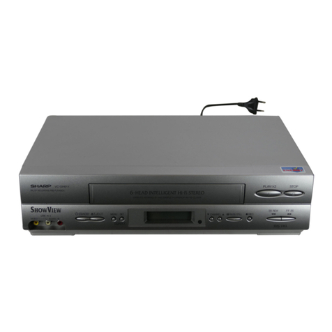
Sharp
Sharp VC-FH30FPM User manual

Sharp
Sharp VC-A250X User manual

Sharp
Sharp VC-GH60SM User manual

Sharp
Sharp VC-M303HM User manual

Sharp
Sharp VC-M311AHM User manual

Sharp
Sharp VC-M35SM User manual
Sharp
Sharp VC-A413U User manual

Sharp
Sharp VC-H998U User manual

Sharp
Sharp VC-581N User manual

Sharp
Sharp VC-SA350 User manual

Sharp
Sharp VC-A310X User manual

Sharp
Sharp VC-MH780BM User manual
Sharp
Sharp DV-NC200SS User manual

Sharp
Sharp VC-488NS User manual

Sharp
Sharp VC-MH71SM User manual

Sharp
Sharp vc-a260x User manual

Sharp
Sharp VC-A560UA User manual